Note: Descriptions are shown in the official language in which they were submitted.
CA 02885052 2015-03-13
WO 2014/058648 PCT/US2013/062686
SEPARATING CARBON DIOXIDE FROM NATURAL GAS LIQUIDS
CROSS-REFERENCE TO RELATED APPLICATION
100011 This application claims the benefit of U.S. Provisional Patent
Application
61/711,130 filed October 8, 2012 entitled SEPARATING CARBON DIOXIDE FROM
NATURAL GAS LIQUIDS, the entirety of which is incorporated by reference
herein.
FIELD OF THE INVENTION
[00021 Exemplary embodiments of the present techniques are directed to the
separation
of carbon dioxide (CO2) from natural gas liquids (NGLs). More specifically,
exemplary
embodiments of the present techniques are directed to the separation of CO2
from a
hydrocarbon stream containing NGLs by cooling the hydrocarbon stream below the
freezing
point of CO2 and removing the resulting CO2 solids from the hydrocarbon
stream.
BACKGROUND
[00031 This section is intended to introduce various aspects of the art,
which may be
associated with exemplary embodiments of the present techniques. This
discussion is
believed to assist in providing a framework to facilitate a better
understanding of particular
aspects of the present techniques. Accordingly, it should be understood that
this section
should be read in this light, and not necessarily as admissions of prior art.
10004I Natural gas reservoirs may often contain high levels of acid
gases, such as carbon
dioxide (CO2). In these cases, a cryogenic process may provide an efficacious
way to
separate the acid gases from the methane. The cryogenic process could include
a simple bulk
fractionation, a Ryan-Holmes process, or a more complex cryogenic
fractionation process.
The cryogenic processes separate methane from CO2 by condensation and
fractionation, and
can produce the acid gas in a liquid phase for efficient disposal via pumping.
However, in
the cryogenic processes, hydrocarbons heavier than methane, e.g., natural gas
liquids
(NGLs), are separated with the CO2 in a single liquid stream. Often, the CO2
will be
immediately reinjected for disposal.
[00051 In some locations, a natural gas reservoir contains high levels
of CO2. In such
locations, it may be desirable to use a cryogenic process to separate the CO2
from the
methane. The cryogenic process could be a simple bulk fractionation process, a
Ryan-
Holmes process, or a Controlled Freeze Zone (CFZTM) process. These processes
separate
- 1 -
CA 02885052 2015-03-13
WO 2014/058648 PCT/US2013/062686
methane from CO2 by condensation or fractionation, and can provide the CO2 as
a liquid for
efficient disposal. However, in these processes, the NGLs are also condensed
and separated
with the CO2. Normally, the CO2 will be reinjected for disposal. However, the
NGLs are
valuable. Thus, it may be desirable to recover the NGLs for sale.
100061 Separation of the NGLs can be performed by fractionation. However,
ethane
forms an azeotropic mixture with CO2, as discussed with respect to Fig. 1.
Such an
azeotropic mixture may prevent separation by normal techniques.
100071 Fig. 1 is a temperature-composition phase plot 100 showing the
equilibrium
concentrations of CO2 in a mixture with ethane at 4,137 kilopascals (kPa, 600
psia). The x-
axis 102 indicates the mole fraction of CO2, while the
y-axis 104 represents the temperature in degrees Celsius ( C). The
concentration of the CO2
in the vapor phase 106 matches the concentration of the CO2 in the liquid
phase 108 at about
70 % CO2 / 30 % ethane, as indicated by an arrow 110. This prevents separation-
by-
fractionation across the azeotrope (left to right, or right to left).
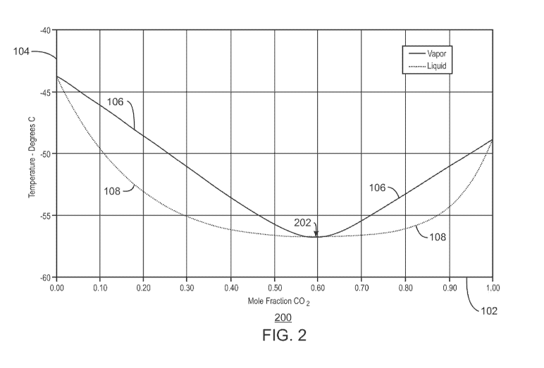
100081 Fig. 2 is a temperature-composition phase plot 200 showing the
equilibrium
concentrations of CO2 in a mixture with ethane at 689.5 kPa (100 psia). Like
numbered items
are as described with respect to Fig. 1. As this plot 200 shows, concentration
of the CO2 in
the vapor phase 106 approaches the concentration of the CO2 in the liquid
phase 108 at about
60 % CO2 / 40 % ethane, as indicated by an arrow 202. This prevents separation-
by-
fractionation across the azeotrope (left to right, or right to left). As these
plots 100 and 200
indicate, complete separation by fractionation cannot be achieved without some
additional
separation processes.
100091 Current practices for CO2 / ethane separation includes various
methods. For
example, a heavy component (lean oil) can be added, which preferentially
absorbs the ethane.
This is called "extractive distillation." As another example, two-pressure
fractionation can be
used to exploit the small difference in the azeotropic composition between
different
pressures, for example, using two fractionators to fractionate at both 4,137
kPa and 689.5
kPa. However, this technique utilizes a very large recycle stream and large
fractionation
systems. Further, the compressors needed to move from the low pressure to the
high pressure
column make the technique very energy intensive. Methods to exploit other
physical and
chemical properties can be used in conjunction with fractionation to achieve
separation.
These methods may include the use of amines in a chemical reaction with CO2,
gas
permeation membranes, or molecular sieves.
- 2 -
CA 02885052 2015-03-13
WO 2014/058648 PCT/US2013/062686
100101 For example, U.S. Patent No. 4,246,015, to Styring, discloses a
method for
separating CO2 and ethane based on washing ethane from frozen CO2. The
separation is
accomplished by freezing the CO2 in a CO2 and ethane mixture and washing the
ethane from
the solid CO2 with a liquid hydrocarbon, e.g., lean oil, having at least three
carbon atoms.
The freezing process may be preceded by distillation of a CO2-ethane mixture
to form an
azeotropic mixture. A subsequent distillation may be used to separate the wash
hydrocarbon
from the CO2. In addition, if desired, the ethane-wash hydrocarbon mixture may
be similarly
separated in a subsequent distillation stage. However, the use of lean oil
results in the
contamination of the ethane, and utilizes large amounts of heat for
regenerating the lean oil.
Further, high lean oil circulation rates are needed, and the ethane is not
able to be completely
recovered.
10011] U.S. Patent Application Publication No. 2002/0189443, by McGuire,
discloses a
method of removing CO2 or hydrogen sulfide (H25) from a high pressure mixture
with
methane. The high pressure mixture is expanded through a flow channel having a
convergent
section followed by a divergent section with an intervening throat that
functions as an
aerodynamic expander. The flow channel is operated at temperatures low enough
to result in
the formation of solid CO2 and solid H25 particles, which increases the
efficiency of CO2 and
H25 removal. However, such techniques rely on the use of a high pressure
mixture with a
high proportion of methane and a relatively low proportion of CO2. In some
cases, it may be
desirable to remove CO2 from a mixture that contains a large proportion of
CO2, e.g., more
than around 40% CO2.
100121 International Patent Publication No. WO/2008/095258, by Hart,
discloses a
method for decreasing the concentration of CO2 in a natural gas feed stream
containing
ethane and C3+ hydrocarbons. The process involves cooling the natural gas feed
stream
under a first set of conditions to produce a liquid stream including CO2,
ethane, and C3+
hydrocarbons and a gas stream having a reduced CO2 concentration. The liquid
stream is
separated from the gas stream, and C3+ hydrocarbons may be separated from the
liquid
stream. The gas stream is then cooled under a second set of conditions to
produce a
sweetened natural gas stream and a second liquid containing liquid CO2 and/or
CO2 solids.
The sweetened natural gas stream is separated from the second liquid. However,
this
technique relies on the use of amines, membranes, and molecular sieves, which
release the
CO2 as a vapor at low pressure and increase the cost of disposal.
100131 International Patent Publication No. WO/2009/084945, by Prast,
discloses a
method and assembly for removing and solidifying CO2 from a fluid stream. The
assembly
- 3 -
CA 02885052 2015-03-13
WO 2014/058648 PCT/US2013/062686
has a cyclonic fluid separator with a tubular throat portion arranged between
a converging
fluid inlet section and a diverging fluid outlet section and a swirl creating
device. The
separation vessel has a tubular section positioned on and in connection with a
collecting tank.
A fluid stream with CO2 is injected into the separation assembly. A swirling
motion is
imparted to the fluid stream so as to induce outward movement. The swirling
fluid stream is
then expanded such that components of CO2 in a meta-stable state within the
fluid stream are
formed. Subsequently, the outward fluid stream with the components of CO2 is
extracted
from the cyclonic fluid separator and provided as a mixture to the separation
vessel. The
mixture is then guided through the tubular section towards the collecting
tank, while
providing processing conditions such that solid CO2 is formed. Finally,
solidified CO2 is
extracted. However, this technique may not provide for an acceptable degree of
separation of
the CO2, since the CO2 may form an azeotrope with the other components of the
fluid stream
as the fluid stream flows through the tubular section towards the collecting
tank.
SUMMARY
100141 An embodiment described herein provides a method for separating
carbon dioxide
from heavy hydrocarbons. The method includes cooling a first liquid stream
including
carbon dioxide and heavy hydrocarbons within an oscillatory crystallization
unit to generate
carbon dioxide solids and a second liquid stream including the heavy
hydrocarbons. The
method also includes separating the carbon dioxide solids from the second
liquid stream via a
solid-liquid separation system.
100151 Another embodiment provides a system for separating carbon
dioxide from heavy
hydrocarbons. The system includes an oscillatory crystallization unit
configured to cool a
first liquid stream including carbon dioxide and heavy hydrocarbons to
generate carbon
dioxide solids and a second liquid stream including the heavy hydrocarbons.
The system also
includes a solid-liquid separation system configured to separate the carbon
dioxide solids
from the second liquid stream.
100161 Another embodiment provides a system for removing carbon dioxide
from natural
gas liquids. The system includes a methane separation system configured to
separate
methane from a liquid stream including carbon dioxide and natural gas liquids.
The system
includes a heat exchanger configured to cool the liquid stream to a
temperature that is slightly
above a freezing point of the carbon dioxide and a pressure reducing device
configured to
reduce a pressure of the liquid stream. The system also includes a continuous
oscillatory
baffled crystallizer configured to generate carbon dioxide solids and a
natural gas liquids
- 4 -
CA 02885052 2015-03-13
WO 2014/058648 PCT/US2013/062686
stream by radially cooling the liquid stream to a temperature that is below
the freezing point
of the carbon dioxide. The system further includes a solid-liquid separation
system
configured to separate the carbon dioxide solids from the natural gas liquids
stream.
BRIEF DESCRIPTION OF THE DRAWINGS
100171 The advantages of the present techniques are better understood by
referring to the
following detailed description and the attached drawings, in which:
100181 Fig. 1 is a temperature-composition phase plot showing the
equilibrium
concentrations of carbon dioxide (CO2) in a mixture with ethane at 4,137 kPa;
[00191 Fig. 2 is a temperature-composition phase plot showing the
equilibrium
concentrations of CO2 in a mixture with ethane at 689.5 kPa;
100201 Fig. 3 is a plot of the freezing conditions used to form solid
CO2 in a mixture with
a hydrocarbon;
100211 Fig. 4 is a block diagram of a system that can be used to
separate CO2 from
natural gas liquids (NGLs);
100221 Fig. 5 is a block diagram of the system of Fig. 4 with the
addition of an azeotropic
distillation system;
[00231 Fig. 6 is a process flow diagram of a system that can be used to
separate CO2 from
NGLs using a continuous oscillatory baffled crystallizer (COBC);
100241 Fig. 7 is a process flow diagram of the system of Fig. 6 with the
addition of a
recirculation system for increasing the degree of separation of the CO2 and
the NGLs;
100251 Fig. 8 is a schematic of a circuitous COBC that can be used to
form CO2 solids;
100261 Fig. 9 is a schematic of a vertical COBC that can be used to form
CO2 solids;
[00271 Fig. 10 is a schematic of a cyclonic separator that can used to
separate CO2 solids
from NGL; and
100281 Fig. 11 is a process flow diagram of a method for separating CO2
from NGLs.
DETAILED DESCRIPTION
100291 In the following detailed description section, specific
embodiments of the present
techniques are described. However, to the extent that the following
description is specific to
a particular embodiment or a particular use of the present techniques, this is
intended to be
for exemplary purposes only and simply provides a description of the exemplary
embodiments. Accordingly, the techniques are not limited to the specific
embodiments
- 5 -
CA 02885052 2015-03-13
WO 2014/058648 PCT/US2013/062686
described herein, but rather, include all alternatives, modifications, and
equivalents falling
within the true spirit and scope of the appended claims.
[00301 At the outset, for ease of reference, certain terms used in this
application and their
meanings as used in this context are set forth. To the extent a term used
herein is not defined
below, it should be given the broadest definition persons in the pertinent art
have given that
term as reflected in at least one printed publication or issued patent.
Further, the present
techniques are not limited by the usage of the terms shown below, as all
equivalents,
synonyms, new developments, and terms or techniques that serve the same or a
similar
purpose are considered to be within the scope of the present claims.
[00311 "Acid gases" are contaminants that are often encountered in natural
gas streams.
Typically, these gases include carbon dioxide (CO2) and hydrogen sulfide
(H2S), although
any number of other contaminants may also form acids. Acid gases are commonly
removed
by contacting the gas stream with an absorbent, such as an amine, which may
react with the
acid gas. When the absorbent becomes acid-gas "rich," a desorption step can be
used to
separate the acid gases from the absorbent. The "lean" absorbent is then
typically recycled
for further absorption. As used herein a "liquid acid gas stream" is a stream
of acid gases that
are condensed into the liquid phase, for example, including CO2 dissolved in
H2S and vice-
versa.
100321 An "azeotrope" or "azeotropic mixture" is a system of two or more
components in
which the liquid composition and vapor composition are equal at a certain
pressure and
temperature. In practice, this means that the components of an azeotropic
mixture are
constant-boiling at that pressure and temperature and generally cannot be
separated during a
phase change.
[00331 As used herein, a "column" is a separation vessel in which a
counter current flow
is used to isolate materials on the basis of differing properties. In an
absorbent column, a
physical solvent is injected into the top, while a mixture of gases to be
separated is flowed
through the bottom. As the gases flow upwards through the falling stream of
absorbent, one
gas species is preferentially absorbed, lowering its concentration in the
vapor stream exiting
the top of the column. In a fractionation column, liquid and vapor phases are
counter-
currently contacted to effect separation of a fluid mixture based on boiling
points or vapor
pressure differences. The high vapor pressure, or lower boiling, component
will tend to
concentrate in the vapor phase whereas the low vapor pressure, or higher
boiling, component
will tend to concentrate in the liquid phase.
- 6 -
CA 02885052 2015-03-13
WO 2014/058648 PCT/US2013/062686
100341 "Compressor" refers to a device for compressing a working gas,
including gas-
vapor mixtures or exhaust gases. Compressors can include pumps, compressor
turbines,
reciprocating compressors, piston compressors, rotary vane or screw
compressors, and
devices and combinations capable of compressing a working gas.
10035] As used herein, the term "Controlled Freeze Zone (CFZ) process"
generally refers
to a process whereby acid gas components are separated by cryogenic
distillation through the
controlled freezing and melting of CO2 in a single column, without the use of
freeze-
suppression additives. The CFZ process uses a cryogenic distillation column
with a special
internal section (CFZ section) to handle the solidification and melting of
CO2. This CFZ
section does not contain packing or trays like conventional distillation
columns. Instead, it
contains one or more spray nozzles and a melting tray. Solid CO2 forms in the
vapor space in
the distillation column and falls into the liquid on the melting tray.
Substantially all of the
solids that form are confined to the CFZ section. The portions of the
distillation tower above
and below the CFZ section of the tower are similar to conventional cryogenic
demethanizer
columns.
10036] As used herein, "cooling" broadly refers to lowering and/or
dropping a
temperature and/or internal energy of a substance, such as by any suitable
amount. Cooling
may include a temperature drop of at least about 1 C, at least about 5 C, at
least about 10 C,
at least about 15 C, at least about 25 C, at least about 50 C, at least
about 100 C, and/or the
like. The cooling may use any suitable heat sink, such as steam generation,
hot water
heating, cooling water, air, refrigerant, other process streams (integration),
and combinations
thereof One or more sources of cooling may be combined and/or cascaded to
reach a desired
outlet temperature. The cooling step may use a cooling unit with any suitable
device and/or
equipment. According to one embodiment, cooling may include indirect heat
exchange, such
as with one or more heat exchangers. Heat exchangers may include any suitable
design, such
as shell and tube, plate and frame, counter current, concurrent, extended
surface, and/or the
like. In the alternative, the cooling may use evaporative (heat of
vaporization) cooling and/or
direct heat exchange, such as a liquid sprayed directly into a process stream.
100371 "Cryogenic distillation" has been used to separate CO2 from
methane since the
relative volatility between methane and CO2 is reasonably high. The overhead
vapor is
enriched with methane and the bottoms product is enriched with CO2 and other
heavier
hydrocarbons. Cryogenic distillation processing requires the proper
combination of pressure
and temperature to achieve the desired product recovery.
- 7 -
CA 02885052 2015-03-13
WO 2014/058648 PCT/US2013/062686
100381 "Cryogenic temperature" refers to a temperature that is about ¨50
C or below.
100391 A "facility" as used herein is a representation of a tangible
piece of physical
equipment through which hydrocarbon fluids are either produced from a
reservoir or injected
into a reservoir. In its broadest sense, the term facility is applied to any
equipment that may
be present along the flow path between a reservoir and the destination for a
hydrocarbon
product. Facilities may comprise production wells, injection wells, well
tubulars, wellhead
equipment, gathering lines, manifolds, pumps, compressors, separators, surface
flow lines,
and delivery outlets. In some instances, the term "surface facility" is used
to distinguish
those facilities other than wells. A "facility network" is the complete
collection of facilities
that are present in the model, which would include all wells and the surface
facilities between
the wellheads and the delivery outlets.
10040] The term "gas" is used interchangeably with "vapor," and means a
substance or
mixture of substances in the gaseous state as distinguished from the liquid or
solid state.
Likewise, the term "liquid" means a substance or mixture of substances in the
liquid state as
distinguished from the gas or solid state.
100411 "Heat exchanger" refers to any equipment arrangement adapted to
allow the
passage of heat energy from one or more streams to other streams. The heat
exchange may
be either direct (e.g., with the streams in direct contact) or indirect (e.g.,
with the streams
separated by a mechanical barrier). The streams exchanging heat energy may be
one or more
lines of refrigerant, heating, or cooling utilities, one or more feed streams,
or one or more
product streams. Examples include a shell-and-tube heat exchanger, a cryogenic
spool-
wound heat exchanger, or a brazed aluminum-plate fin type, among others.
100421 A "hydrocarbon" is an organic compound that primarily includes
the elements
hydrogen and carbon, although nitrogen, sulfur, oxygen, metals, or any number
of other
elements may be present in small amounts. As used herein, hydrocarbons
generally refer to
organic materials that are harvested from hydrocarbon containing sub-surface
rock layers,
termed reservoirs. For example, natural gas is normally composed primarily of
the
hydrocarbon methane.
100431 The term "natural gas" refers to a multi-component gas obtained
from a crude oil
well (associated gas) or from a subterranean gas-bearing formation (non-
associated gas). The
composition and pressure of natural gas can vary significantly. A typical
natural gas stream
contains methane (C1) as a significant component. Raw natural gas will also
typically
contain ethane (C2), higher molecular weight hydrocarbons, one or more acid
gases (such as
- 8 -
CA 02885052 2015-03-13
WO 2014/058648 PCT/US2013/062686
CO2, HS, carbonyl sulfide, carbon disulfide, and mercaptans), and minor
amounts of
contaminants such as water, helium, nitrogen, iron sulfide, wax, and crude
oil.
[00441 As used herein, "natural gas liquids" (NGL) refer to mixtures of
hydrocarbons
whose components are, for example, typically heavier than ethane. Some
examples of
hydrocarbon components of NGL streams include propane, butane, and pentane
isomers,
benzene, toluene, and other aromatic compounds.
100451 As used herein, the term "oscillatory crystallization unit"
refers to a cylindrical
tube or column containing baffles in which a liquid is oscillated axially by
means of a
diaphragm, bellows, piston, or other device located at one or both ends of the
tube. More
specifically, a "continuous oscillatory baffled crystallizer (COBC)" is an
oscillatory
crystallization unit in which the degree of mixing of the liquid is governed
by the frequency
and magnitude of the induced oscillations and the size, number, and type of
the baffles within
the unit. A COBC may be operated horizontally, vertically, or at any angle,
and may include
a circuitous tube or a single straight tube, for example.
100461 "Pressure" is the force exerted per unit area by the gas on the
walls of the volume.
Pressure can be shown as pounds per square inch (psi). "Atmospheric pressure"
refers to the
local pressure of the air. "Absolute pressure" (psia)" refers to the sum of
the atmospheric
pressure (14.7 psia at standard conditions) plus the gauge pressure (psig).
"Gauge pressure"
(psig) refers to the pressure measured by a gauge, which indicates only the
pressure
exceeding the local atmospheric pressure (i.e., a gauge pressure of 0 psig
corresponds to an
absolute pressure of 14.7 psia). The term "vapor pressure" has the usual
thermodynamic
meaning. For a pure component in an enclosed system at a given pressure, the
component
vapor pressure is essentially equal to the total pressure in the system.
[00471 The "Ryan-Holmes process" is a process by which methane and CO2
are separated
in a distillation column. The Ryan-Holmes process involves operation of the
distillation
column at temperatures, compositions, and pressures that produce a solids
potential zone for
CO2 within the column. The term "solids potential zone" is used with the Ryan-
Holmes
process because, although conditions in the tower are such that CO2 solids
would normally
occur, the Ryan-Holmes process prevents actual solids formation from
occurring. This is
achieved by introducing into the upper portion of the distillation column an
additive to
suppress formation of acid gas solids. The Ryan-Holmes additive, which is a
non-polar
material that is miscible with methane, may include ethane, propane, butane,
pentane, and
mixtures thereof After the methane/CO2 separation, the additive is recovered
in another
distillation column.
- 9 -
CA 02885052 2015-03-13
WO 2014/058648 PCT/US2013/062686
100481 A "separation vessel" is a vessel wherein an incoming feed is
separated into
individual vapor and liquid fractions. A separation vessel may include a flash
drum in which
a stream is flashed to form vapor and liquid components. The vapor component
is removed
from an upper outlet, while the liquid component is removed from a lower
outlet.
10049] "Substantial" when used in reference to a quantity or amount of a
material, or a
specific characteristic thereof, refers to an amount that is sufficient to
provide an effect that
the material or characteristic was intended to provide. The exact degree of
deviation
allowable may in some cases depend on the specific context.
100501 "Well" or "wellbore" refers to a hole in the subsurface made by
drilling or
insertion of a conduit into the subsurface. The terms are interchangeable when
referring to an
opening in the formation. A well may have a substantially circular cross
section, or other
cross-sectional shapes (for example, circles, ovals, squares, rectangles,
triangles, slits, or
other regular or irregular shapes). Wells may be cased, cased and cemented, or
open-hole
well, and may be any type, including, but not limited to a producing well, an
experimental
well, an exploratory well, or the like. A well may be vertical, horizontal, or
any angle
between vertical and horizontal (a deviated well), for example a vertical well
may comprise a
non-vertical component.
Overview
100511 Techniques described herein relate to the separation of a liquid
hydrocarbon
stream including CO2 and NGLs into its respective components. Specifically, an
oscillatory
crystallization unit is used to form CO2 solids, which are then separated from
the NGLs using
a solid-liquid separation system. The oscillatory crystallization unit may
gradually cool the
liquid stream via radial mixing. This may provide for a substantially complete
separation of
the CO2 from the NGLs by preventing the formation of an azeotrope. This
process may be
further understood with respect to Fig. 3.
100.21 Fig. 3 is a plot 300 of the freezing conditions used to form
solid CO2 in a mixture
with a hydrocarbon. In the plot 300, the x-axis 302 represents the temperature
of the mixture
in degrees Fahrenheit, while the y-axis 304 represents the CO2 content of the
liquid phase in
mol %. The line 306 on the plot 300 represents a division between a first
region 308 in which
solid CO2 forms, and a second region 310 in which solid CO2 does not form. As
shown at
point 312 in the plot 300, at temperatures of about -62 C, solid CO2 forms
from a
70 % I 30 %: CO2 I ethane mixture. Ethane, however, does not freeze, but will
be either a
vapor or liquid, depending on the pressure, temperature, and residual CO2
level. The solid
will be nearly pure CO2, resulting in the separation of the CO2 and the
ethane.
- 10 -
CA 02885052 2015-03-13
WO 2014/058648 PCT/US2013/062686
Systems for Separating CO2 from NGLs
100531 Fig. 4 is a block diagram of a system 400 that can be used to
separate CO2 402
from NGLs 404. The resulting NGLs 404, which include ethane and heavier
hydrocarbons,
may be exported and used as fuel. In addition, the resulting CO2 402 may be
used for
enhanced oil recovery (EOR) operations or commercial sales, for example.
100541 Within the system 400, a hydrocarbon feed stream 406 may be fed
to a separation
system 408. The hydrocarbon feed stream 406 may be a raw hydrocarbon feed
stream
obtained directly from one or more production wells. Alternatively, the
hydrocarbon feed
stream 406 may be a hydrocarbon feed stream that has been dehydrated within a
dehydration
unit. Such a dehydration unit may include any system that is capable of
removing water
vapor from a raw hydrocarbon feed stream using glycol dehydration, desiccants,
or pressure
swing adsorption (PSA) techniques, among others. The removal of water from the
hydrocarbon feed stream 406 may prevent the water from freezing or plugging
downstream
cryogenic separation systems.
100551 The separation system 408 may use any number of processes to
separate methane
410 from various other components within the hydrocarbon feed stream 406,
including heavy
hydrocarbons, e.g., C2 and higher hydrocarbons, CO2 402, H25, and other acid
gases. The
separation system 408 may include a methane separation column, a bulk
fractionator, a
physical solvent system, or a cryogenic distillation unit, such as, for
example, a Ryan-Holmes
column or a CFZ column. In addition, any number of other systems may be used
for the
separation process. For example, any type of warm gas processing system may be
used.
100561 The separation of the methane 410 from the other components
within the
hydrocarbon feed stream 406 may result in the generation of a liquid stream
412 including
the CO2 402 and the heavy hydrocarbons, which may combine to form NGLs 404, as
well as
H25 and other acid gases. The CO2 402 and the NGLs 404 within the liquid
stream 412 may
form an azeotropic mixture, making separation of the two components difficult.
10057l The methane 410 may be flowed out of the separation system 408
via an overhead
line, and the liquid stream 412 may be flowed out of the separation system 408
via a bottoms
line. The liquid stream 412 exiting the separation system 408 may be at a
temperature that is
approaching the boiling point of the CO2 402. For example, the liquid stream
412 may be at
temperature that is between about -1 C (about 30 F) to about 10 C (about 50
F).
100581 From the separation system 408, the liquid stream 412 may be
flowed through a
heat exchanger 414. The heat exchanger 414 may cool the liquid stream 412 to a
temperature
that is at least slightly above the freezing point of the CO2 402. For
example, the heat
-11-
CA 02885052 2015-03-13
WO 2014/058648 PCT/US2013/062686
exchanger 414 may cool the liquid stream 412 to about -62 C (about -80 F).
The heat
exchanger 414 may be any type of chilling device, such as a shell-and-tube
heat exchanger, a
brazed aluminum heat exchanger, a double pipe heat exchanger, or a chiller
bundle heat
exchanger, among others. In addition, the heat exchanger 414 may utilize any
suitable type
of cooling fluid to cool the liquid stream 412 via indirect heat exchange,
such as an ammonia
stream, a propane stream, or a process stream for another stage of the
process.
100591 The resulting low-temperature liquid stream 416 may be flowed
from the heat
exchanger 414 to a pressure reducing device 418. In various embodiments, the
cooling of the
liquid stream 412 within the heat exchanger 414 prevents flashing of the
resulting low-
temperature liquid stream 416 within the pressure reducing device 418. The
pressure
reducing device 418 may lower the pressure of the low-temperature liquid
stream 416 to
prepare for the formation of CO2 solids, since CO2 is more likely to undergo a
phase change
from liquid to solid under low pressures. The pressure reducing device 418 may
be any
suitable type of throttling valve.
100601 From the pressure reducing valve 418, the resulting low-pressure
liquid stream
420 may be flowed into an oscillatory crystallization unit 422. The
oscillatory crystallization
unit 422 may radially mix the low-pressure liquid stream 420 to gradually cool
the low-
pressure liquid stream 420 below the freezing point of the CO2 402. For
example, the
oscillatory crystallization unit 422 may cool the low-pressure liquid stream
420 via indirect
heat exchange with any suitable type of cooling fluid. In various embodiments,
the
oscillatory crystallization unit 422 is a COBC, such as either a circuitous
COBC or a simple
vertical COBC, as discussed further with respect to Figs. 8 and 9.
100611 Cooling the low-pressure liquid stream 420 below the freezing
point of the CO2
402 results in the formation of CO2 solids within the low-pressure liquid
stream 420. The
vibration and mixing of the low-pressure liquid stream 420 in the oscillatory
crystallization
unit 422 may prevent the CO2 solids from adhering to the walls, ensuring that
the CO2 solids
continue to flow and do not plug the unit.
100621 From the oscillatory crystallization unit 422, the multiphase
stream 424 may be
flowed into a solid-liquid separation system 426. The solid-liquid separation
system 426 may
separate the multiphase stream 424 into the CO2 402 and the NGLs 404. This may
be
accomplished via any of a number of different separation techniques. For
example, the solid-
liquid separation device 426 may include a gravity separation device, a
cyclonic separation
device, or a filtering device, among others.
- 12 -
CA 02885052 2015-03-13
WO 2014/058648 PCT/US2013/062686
100631 The CO2 402 may be flowed out of the solid-liquid separation
system 426 as a
bottoms stream in either a liquid phase or a solid phase, depending on the
details of the
specific implementation. If the CO2 402 is in the solid phase, some amount of
the NGLs 404
may be used as a carrier fluid for the CO2 solids. In addition, the NGLs 404
may be flowed
out of the solid-liquid separation system 426 as an overhead stream. H2S and
any other acid
gases or residual components within the multiphase stream 424 may also be
removed with the
NGLs 404.
100641 The block diagram of Fig. 4 is not intended to indicate that the
system 400 is to
include all the components shown in Fig. 4. Further, any number of additional
components
not shown in Fig. 4 may be included within the system 400.
100651 The system 400 discussed herein may be suitable for the removal
of an acceptable
proportion of the CO2 from a liquid stream 412 that has an initial
concentration of about 60 %
CO2 402 and about 40 % NGLs 404, or about 70 % CO2 402 and about 30 % NGLs
404, for
example. However, if the liquid stream 412 has an initial concentration of
about 90 % CO2
402 and 10 % NGLs 404, or around 92 % CO2 402 and 8 % NGLs 404, the resulting
NGLs
404 may still contain an unacceptably high proportion of CO2. In such cases,
additional
separation techniques may be employed, as discussed further with respect to
Fig. 5. Further,
in various embodiments, the degree of separation of the CO2 402 from the NGLs
404 is
adjusted such that the multiphase stream 424 has a sufficient amount of liquid
to carry the
solid CO2 out of the oscillatory crystallization unit 422 and into the solid-
liquid separation
system 426.
100661 Fig. 5 is a block diagram of the system 400 of Fig. 4 with the
addition of an
azeotropic distillation system 500. Like numbered items are as described with
respect to Fig.
4. The azeotropic distillation system 500 may separate residual CO2 from the
NGLs 404
exiting the solid-liquid separation system 426. More specifically, the
azeotropic distillation
system 500 may generate purified NGLs 502 and an azeotropic mixture 504
including CO2
and some amount of the NGLs 404.
100671 The azeotropic mixture 504 may be flowed back into the system 400
upstream of
the oscillatory crystallization unit 422. Thus, the azeotropic mixture 504 may
be combined
with the low-pressure liquid stream 420, and CO2 solids may be formed from the
combined
liquid stream within the oscillatory crystallization unit 422. According to
this technique, the
NGLs 404 may be continuously purified until they contain an acceptably low
proportion of
CO2.
- 13 -
CA 02885052 2015-03-13
WO 2014/058648 PCT/US2013/062686
100681 In some embodiments, the azeotropic mixture 504 is flowed back
into the system
400 upstream of the heat exchanger 414. The azeotropic mixture 504 may be
combined with
the liquid stream 412 exiting the separation system 408, and may be used to
aid in the cooling
of the liquid stream 412 prior to entry into the heat exchanger 414. This may
reduce the heat
duty of the heat exchanger 414, resulting in cost savings.
100691 The block diagram of Fig. 5 is not intended to indicate that the
system 400 is to
include all the components shown in Fig. 5. Further, any number of additional
components
not shown in Fig. 5 may be included within the system 500.
100701 Fig. 6 is a process flow diagram of a system 600 that can be used
to separate CO2
602 from NGLs 604 using a COBC 606. A hydrocarbon feed stream 608 may be
flowed into
the system 600 directly from one or more production wells, or from a
dehydration unit, for
example. The hydrocarbon feed stream 608 may include methane 610, ethane and
heavier
hydrocarbons, CO2 602, H2S and other acid gases, and any other residual
contaminants.
100711 The hydrocarbon feed stream 608 may be injected into a cryogenic
fractionation
column 612. The cryogenic fractionation column 612 may be a CFZ column or a
Ryan-
Holmes column, for example. The cryogenic fractionation column 612 may
separate the
methane 610 from the ethane and heavier hydrocarbons, CO2 602, and other
components
within the hydrocarbon feed stream 608.
100721 The methane 610 may be flowed out of the cryogenic distillation
column 612 as
an overhead stream 614. The overhead stream 614 may also include other low
boiling point
or non-condensable gases, such as nitrogen and helium. The overhead stream 614
may be
flowed through a condenser 616, which may condense the overhead stream 614,
producing a
cooled methane stream 617. The cooled methane stream 617 may then be flowed
into a
reflux drum 618. From the reflux drum 618 a portion of the cooled methane
stream 616 may
be flowed out of the system 600 as a methane stream 610, and the remaining
portion of the
cooled methane stream 617 may be reinjected into the cryogenic fractionation
column 612 as
a reflux stream 620 to aid in the separation process.
100731 The ethane and heavier hydrocarbons, CO2 602, and other
components within the
hydrocarbon feed stream 608 may be flowed out of the cryogenic fractionation
column 612 as
a bottoms stream 622. The bottoms stream 622 may then be heated within a
reboiler 624, and
a portion of the heated bottoms stream 622 may be returned to the cryogenic
fractionation
column 612 to provide heating. The remaining portion of the heated bottoms
stream 622 may
be a liquid stream 626 from which separate ethane and CO2 streams are to be
generated.
- 14 -
CA 02885052 2015-03-13
WO 2014/058648 PCT/US2013/062686
100741 The liquid stream 626 may be flowed into a heat exchanger 628.
The heat
exchanger 628 may be a shell-and-tube heat exchanger, a brazed aluminum heat
exchanger, a
double pipe heat exchanger, or a chiller bundle heat exchanger, among others.
The heat
exchanger 628 may pre-cool the liquid stream via indirect heat exchange with a
cooling fluid
630. In some embodiments, the heat exchanger 628 cools the liquid stream 626
to a
temperature that is slightly above the freezing point of CO2.
100751 The resulting high-temperature liquid stream 632 may be flowed
through a
pressure reducing device 634. The pressure reducing device 634 may be any type
of device
or valve that is capable of decreasing the pressure of the high-temperature
liquid stream 632,
producing a low-pressure liquid stream 636.
100761 The low-pressure liquid stream 636 may be flowed into the COBC
606. The
COBC 606 may radially cool the high-temperature liquid stream 636 to a
temperature that is
below the freezing point of the CO2 602 via indirect heat exchange with a
cooling fluid 640.
Further, the COBC 606 may use vibrations to prevent the CO2 solids from
freezing on the
sides, agglomerating, or plugging the COBC 606. The COBC 606 provides a
multiphase
stream 644 including CO2 solids and NGLs.
[00771 The multiphase stream 644 may be flowed into a solid-liquid
separation system
644. The solid-liquid separation system 644 may be a cyclonic separator or a
separation
column, among others. The solid-liquid separation system 644 may remove the
CO2 solids
from the NGLs. The CO2 602 may be flowed out of the solid-liquid separation
system 644
via a bottoms line 646, and the NGLs 604 may be flowed out of the solid-liquid
separation
system 644 via an overhead line 648. In addition, H2S or other acid gases
within the
multiphase stream 644 may be flowed out of the overhead line 648 along with
the NGLs 604.
[00781 The process flow diagram of Fig. 6 is not intended to indicate
that the system 600
is to include all the components shown in Fig. 6. Further, any number of
additional
components not shown in Fig. 6 may be included within the system 600. For
example, the
system 600 may include a recirculation system, as discussed further with
respect to Fig. 6.
100791 Fig. 7 is a process flow diagram of the system 600 of Fig. 6 with
the addition of a
recirculation system for increasing the degree of separation of the CO2 602
and the NGLs
604. Like numbered items are as described with respect to Fig. 6. The
recirculation system
may be useful for instances in which the proportion of CO2 in the low-pressure
liquid stream
636 is high. In such instances, the COBC 606 may not be able to crystallize
all of the CO2 in
the low-pressure liquid stream 636 in one pass. Therefore, it may be desirable
to reduce the
- 15 -
CA 02885052 2015-03-13
WO 2014/058648 PCT/US2013/062686
proportion of CO2 in the low-pressure liquid stream 636 by flowing a portion
of the NGLs
604 within the overhead line 648 back into the system 600 upstream of the COBC
606.
[00801 Specifically, a portion of the NGLs 604, e.g., a recycle stream
650, may be
pumped back into the system 600 upstream of the COBC 606 via a pump 652. In
addition,
the pressure of the recycle stream 650 may be reduced via a pressure reducing
device 654.
The recycle stream 650 may then be combined with the low-pressure liquid
stream 636. This
may reduce the proportion of CO2 in the low-pressure liquid stream 636. As a
result, the
COBC 606 may be able to more effectively handle the low-pressure liquid stream
636, since
the weight percentage of the resulting CO2 solids may not be as high.
[00811 Further, in some embodiments, CO2 seeds 656 may be added to the low-
pressure
liquid stream 636 prior to entry into the COBC 606. The CO2 seeds 656 may aid
in the
crystallization of the CO2 within the low-pressure liquid stream 636.
100821 Fig. 8 is a schematic of a circuitous COBC 800 that can be used
to form CO2
solids. The circuitous COBC 800 may be implemented within any of the systems
400 or 500
discussed with respect to Figs. 4, 5, 6, or 7. In various embodiments, the
circuitous COBC
800 may produce CO2 solids within a liquid stream 802 that includes CO2 and
NGLs.
[00831 The liquid stream 802 may be flowed into an inner tube 804 of the
circuitous
COBC 800 from a pressure reducing device 806, for example. In addition, a
cooling fluid
808 may be flowed into an outer tube 810 of the circuitous COBC 800. The
cooling fluid
808 within the outer tube 810 of the circuitous COBC 800 may be in indirect
thermal contact
with the liquid stream 802 within the inner tube 804 of the circuitous COBC
800.
100841 The circuitous COBC 800 may include a pump 812. The pump 812 may
produce
a pulsating flow of the liquid stream 802 within the circuitous COBC 800. In
addition, the
circuitous COBC 800 may include a number of baffles 814. The baffles 814 may
produce a
turbulent flow of the liquid stream 802 as the liquid stream 802 contacts each
baffle 814 on
its path through the circuitous COBC 800. Each baffle 814 may also include a
hole 815 in
the center that induces a shear force on the liquid stream 802. The size and
shape of each
baffle 814 may be adjusted according to the flow rate of the liquid stream 802
and the
particular characteristics of the circuitous COBC 800.
100851 The pulsations, turbulence, and shear forces may cause the liquid
stream 802 to
undergo radial mixing as it travels through the circuitous COBC 800. Further,
as the liquid
stream 802 travels through the circuitous COBC 800, CO2 solids may be formed
due to the
cooling of the liquid stream 802 via indirect heat exchange with the cooling
fluid 808. The
radial mixing of the liquid stream 802 may aid in the formation of the CO2
solids. In
- 16-
CA 02885052 2015-03-13
WO 2014/058648 PCT/US2013/062686
addition, the radial mixing of the liquid stream 802 may prevent the CO2
solids from adhering
to the baffles 814 or the walls of the circuitous COBC 800.
[00861 The liquid stream 802 including the CO2 solids may be flowed out
of the inner
tube 804 of the circuitous COBC 800 as a multiphase stream 816. In addition,
the warmed
cooling fluid 808 may be flowed out of the outer tube 810 of the circuitous
COBC 800, and
may be cooled and recycled to the circuitous COBC 800.
100871 The multiphase stream 816 may be flowed into a solid-liquid
separation system
818, which may remove the CO2 solids from the NGLs within the multiphase
stream 814. In
various embodiments, the solid-liquid separation system 818 is a cyclonic
separation, as
discussed further with respect to Fig .10.
100881 Fig. 9 is a schematic of a vertical COBC 900 that can be used to
form CO2 solids.
Like numbered items are as described with respect to Fig. 8. The vertical COBC
900 may be
similar to the circuitous COBC 800 discussed with respect to Fig .8. However,
as shown in
Fig. 9, the vertical COBC 900 may include a single vertical structure, rather
than a circuitous
structure.
100891 Further, in various embodiments, the pump 812 of the vertical
COBC 900 may be
replaced with a thermoacoustic generator. The thermoacoustic generator may
produce a
pulsating flow of the liquid stream 802 using a resonant frequency in the COBC
900. In
addition, the thermoacoustic generator may aid in the cooling of the liquid
stream 802.
100901 Fig. 10 is a schematic of a cyclonic separation 1000 that can used
to separate CO2
1002 from NGLs 1004. The cyclonic separation1000 may be any of the solid-
liquid
separation systems 426, 644, or 818 discussed with respect to Figs. 4-9. The
cyclonic
separation system 1000 may include a cyclonic separator 1006 and a separation
vessel 1008.
[00911 A multiphase stream 1010 may be flowed into the cyclonic
separator 1006 from
an oscillatory crystallization unit 1012. The oscillatory crystallization unit
1012 may be the
oscillatory crystallization unit 422 discussed with respect to Figs. 4 and 5,
the circuitous
COBC 800 discussed with respect to Fig. 6, or the vertical COBC discussed with
respect to
Fig. 7. The multiphase stream 1010 may include CO2 solids 1014 and NGLs.
100921 As the multiphase stream 1010 enters the cyclonic separator 1006,
the location of
the inlet line within the cyclonic separator 1006 may impart a radial
acceleration and a
tangential velocity component to the multiphase stream 1010. A swirl element
may be added
to impart a further radial acceleration through the rotation of twisted swirl
vanes. The swirl
vanes may be arranged parallel or in series on the swirl element. The
tangential velocity of
the multiphase stream 1010 may cause the CO2 solids 1014, which are heavier
and denser
- 17 -
CA 02885052 2015-03-13
WO 2014/058648 PCT/US2013/062686
than the NGLs 1004 within the multiphase stream 1010, to migrate to the outer
rim of the
cyclonic separator 1006 and begin traveling in a wide circular path. The NGLs
1004 may
migrate towards the center of the cyclonic separator 1006 and begin traveling
in a narrow
circular path. As the multiphase stream 1010 nears the end of the cyclonic
separator 1006,
the CO2 solids 1014 may be captured and sent out of the bottom of the cyclonic
separator
1006, along with a small amount of the NGLs 1004. The majority of the NGLs
1004 may be
sent out of the top of the cyclonic separator 1006.
100931 In various embodiments, the CO2 solids 1014 include some amount
of residual
NGLs. Thus, the CO2 solids 1014 may be flowed into the separation vessel 1008.
Within the
separation vessel 1008, the CO2 solids 1014 may settle on the bottom of the
separation vessel
1008, while the NGLs may settle on the top of the separation vessel 1008 along
with some
amount of CO2 that was been incorporated into the NGLs.
100941 The NGLs and incorporated CO2 1016 may be flowed out of the
separation vessel
via an overhead line 1018. The NGLs and incorporated CO2 1016 may then be
combined
with a liquid stream upstream of the oscillatory crystallization unit 1012.
100951 The CO2 solids 1014 that have settled on the bottom of the
separation vessel 1008
may be converted to a liquid phase using a heating coil 1019 or other heating
device. The
liquid CO2 1002 may then be flowed out of a bottoms line 1020 of the
separation vessel
1008.
Method for Separating CO2 from NGLs
100961 Fig. 11 is a process flow diagram of a method 1100 for separating
CO2 from
NGLs. The method 1100 may be implemented within any of the systems 400 or 600
discussed with respect to Figs. 4, 5, 6, or 7. In various embodiments, the
temperature and
pressure of a liquid stream including CO2 and heavy hydrocarbons are reduced
prior to the
beginning of the method 1100. For example, a heat exchanger may be used to
cool the liquid
stream to a temperature that is slightly higher that the freezing point of
CO2, and a pressure
reducing device may be used to reduce the pressure of the liquid stream.
100971 The method 1100 begins at block 1102, at which the liquid stream
including the
CO2 and the heavy hydrocarbons is cooled within an oscillatory crystallization
unit to
generate CO2 solids and a liquid stream including the heavy hydrocarbons. This
may be
accomplished by flowing the liquid stream into a tube including a number of
baffles, radially
mixing the liquid stream via contact with the baffles and a production of
pulsations within the
liquid stream, and radially cooling the liquid stream within the tube via
indirect heat
- 18-
CA 02885052 2015-03-13
WO 2014/058648 PCT/US2013/062686
exchange with a cooling medium. The radial cooling of the liquid stream may
result in the
generation of the CO2 solids.
[0100] At block 1104, the CO2 solids are separated from the liquid
stream including the
heavy hydrocarbons via a solid-liquid separation system. The CO2 solids may
then be flowed
out of the solid-liquid separation system in either a solid or liquid phase,
and the heavy
hydrocarbons may be flowed out of the solid-liquid separation system as a NGL
stream. In
addition, H2S or any other acid gases within the liquid stream may also be
flowed out of the
solid-liquid separation system along with the NGL stream.
[0101] The process flow diagram of Fig. 11 is not intended to indicate
that the steps of
the method 1100 are to be executed in any particular order, or that all steps
of the method
1100 are to be included in every case. Further, any number of additional steps
may be
included within the method 1100, depending on the details of the specific
implementation.
For example, in some embodiments, a separation system may be used to separate
a methane
stream from the liquid stream upstream of the oscillatory crystallization
unit. The methane
stream may then be flowed from the separation system to a heat exchanger that
is upstream of
the oscillatory crystallization unit, and may be used to cool the liquid
stream within the heat
exchanger. The methane stream may be flowed from the separation system to the
oscillatory
crystallization unit, and may be used to cool the liquid stream within the
oscillatory
crystallization unit. Further, in some embodiments, the methane is recycled to
an upstream
CO2 separation system, such as a bulk fractionator, a physical solvent system,
or a cryogenic
distillation unit, such as, for example, a Ryan-Holmes column or a CFZ column.
[0102] In some embodiments, residual CO2 is separated from the NGL
stream to generate
a purified NGL stream and an azeotropic mixture including CO2 and NGL. The
azeotropic
mixture may then be used to cool the liquid stream upstream of the oscillatory
crystallization
unit. Alternatively, the azeotropic mixture may be recycled to the oscillatory
crystallization
unit. The oscillatory crystallization unit may cool the azeotropic mixture,
generating CO2
solids and a third liquid stream including the NGLs.
Embodiments
[0103] Embodiments of the invention may include any combinations of the
methods and
systems shown in the following numbered paragraphs. This is not to be
considered a
complete listing of all possible embodiments, as any number of variations can
be envisioned
from the description herein.
- 19 -
CA 02885052 2015-03-13
WO 2014/058648 PCT/US2013/062686
1. A method for separating carbon dioxide from heavy hydrocarbons,
including:
cooling a first liquid stream including carbon dioxide and heavy hydrocarbons
within
an oscillatory crystallization unit to generate carbon dioxide solids and a
second liquid stream including the heavy hydrocarbons; and
separating the carbon dioxide solids from the second liquid stream via a solid-
liquid
separation system.
2. The method of paragraph 1, including cooling the first liquid stream
within a
heat exchanger upstream of the oscillatory crystallization unit.
3. The method of paragraph 2, wherein the first liquid stream is cooled to
a
temperature that is slightly higher than a freezing point of the carbon
dioxide within the heat
exchanger.
4. The method of any of paragraphs 1 or 2, including reducing a pressure of
the
first liquid stream via a pressure reducing device upstream of the oscillatory
crystallization
unit.
5. The method of any of paragraphs 1, 2 or 4, wherein the first liquid
stream is
cooled to a temperature that is below a freezing point of the carbon dioxide
within the
oscillatory crystallization unit to generate the carbon dioxide solids.
6. The method of any of paragraphs 1, 2, 4, or 5, including separating the
first
liquid stream from a methane stream within a separation system upstream of the
oscillatory
crystallization unit.
7. The method of paragraph 6, including:
flowing the methane stream from the separation system to a heat exchanger that
is
upstream of the oscillatory crystallization unit; and
using the methane stream to cool the first liquid stream within the heat
exchanger.
8. The method of any of paragraphs 6 or 7, including:
flowing the methane stream from the separation system to the oscillatory
crystallization unit; and
using the methane stream to cool the first liquid stream within the
oscillatory
crystallization unit.
9. The method of any of paragraphs 6, 7, or 8, including recycling the
methane
stream to an upstream carbon dioxide separation system.
10. The method of any of paragraphs 1, 2, or 4-6, including
separating hydrogen
sulfide from the carbon dioxide solids along with the second liquid stream
within the solid-
liquid separation system.
- 20 -
CA 02885052 2015-03-13
WO 2014/058648 PCT/US2013/062686
11. The method of any of paragraphs 1, 2, 4-6, or 10, including:
separating residual carbon dioxide from the second liquid stream to generate a
purified heavy hydrocarbon stream and an azeotropic mixture including
carbon dioxide and heavy hydrocarbons; and
using the azeotropic mixture to cool the first liquid stream upstream of the
oscillatory
crystallization unit.
12. The method of any of paragraphs 1, 2, 4-6, 10, or 11, including:
separating residual carbon dioxide from the second liquid stream to generate a
purified heavy hydrocarbon stream and an azeotropic mixture including
carbon dioxide and heavy hydrocarbons; and
recycling the azeotropic mixture to the oscillatory crystallization unit,
wherein the
oscillatory crystallization unit cools the azeotropic mixture to generate
carbon
dioxide solids and a third liquid stream including the heavy hydrocarbons.
13. The method of any of paragraphs 1, 2, 4-6, or 10-12, wherein cooling
the first
liquid stream within the oscillatory crystallization unit includes:
flowing the first liquid stream into a tube including a number of baffles;
radially mixing the first liquid stream via contact with the number of baffles
and a
production of pulsations within the first liquid stream; and
radially cooling the first liquid stream within the tube via indirect heat
exchange with
a cooling medium, wherein the radial cooling of the first liquid stream
results
in the generation of the carbon dioxide solids.
14. The method of paragraph 13, including producing pulsations within the
first
liquid stream via a pump.
15. The method of any of paragraphs 13 or 14, including producing
pulsations
within the first liquid stream via thermoacoustics.
16. A system for separating carbon dioxide from heavy hydrocarbons,
including:
an oscillatory crystallization unit configured to cool a first liquid stream
including
carbon dioxide and heavy hydrocarbons to generate carbon dioxide solids and
a second liquid stream including the heavy hydrocarbons; and
a solid-liquid separation system configured to separate the carbon dioxide
solids from
the second liquid stream.
17. The system of paragraph 16, including a heat exchanger configured to
cool the
first liquid stream upstream of the oscillatory crystallization unit.
-21-
CA 02885052 2015-03-13
WO 2014/058648 PCT/US2013/062686
18. The system of paragraph 17, wherein the heat exchanger is configured to
cool
the first liquid stream to a temperature that is slightly higher than a
freezing point of the
carbon dioxide.
19. The system of any of paragraphs 17 or 18, wherein the heat exchanger
includes a shell-and-tube heat exchanger, a brazed aluminum heat exchanger, a
double pipe
heat exchanger, or a chiller bundle heat exchanger, or any combinations
thereof
20. The system of any of paragraphs 16 or 17, including a pressure reducing
device configured to reduce a pressure of the first liquid stream upstream of
the oscillatory
crystallization unit.
21. The system of any of paragraphs 16, 17, or 20, wherein the oscillatory
crystallization unit is configured to cool the first liquid stream to a
temperature that is below a
freezing point of the carbon dioxide.
22. The system of any of paragraphs 16, 17, 20, or 21, including a
separation
system configured to produce the first liquid stream and a methane stream from
a
hydrocarbon feed stream.
23. The system of paragraph 22, wherein the separation system includes a
methane separation system, controlled freeze zone (CFZ) column, a bulk
fractionator, a
Ryan-Holmes column, or a physical solvent system, or any combinations thereof
24. The system of any of paragraphs 22 or 23, wherein the oscillatory
crystallization unit is configured to use the methane stream to cool the first
liquid stream.
25. The system of any of paragraphs 16, 17, or 20-22, wherein the solid-
liquid
separation system is configured to separate hydrogen sulfide from the carbon
dioxide solids
along with the second liquid stream.
26. The system of any of paragraphs 16, 17, 20-22, or 25, wherein the
oscillatory
crystallization unit includes a continuous oscillatory baffled crystallizer.
27. The system of any of paragraphs 16, 17, 20-22, 25, or 26, including an
azeotropic distillation system configured to separate residual carbon dioxide
from the second
liquid stream to generate a purified heavy hydrocarbon stream and an
azeotropic mixture
including carbon dioxide and heavy hydrocarbons.
28. The system of paragraph 27, wherein the azeotropic mixture is used to
cool the
first liquid stream upstream of the oscillatory crystallization unit.
29. The system of any of paragraphs 27 or 28, wherein the solid-liquid
separation
system includes a cyclonic separator.
- 22 -
CA 02885052 2015-03-13
WO 2014/058648 PCT/US2013/062686
30. A system for removing carbon dioxide from natural gas liquids,
including:
a methane separation system configured to separate methane from a liquid
stream
including carbon dioxide and natural gas liquids;
a heat exchanger configured to cool the liquid stream to a temperature that is
slightly
above a freezing point of the carbon dioxide;
a pressure reducing device configured to reduce a pressure of the liquid
stream;
a continuous oscillatory baffled crystallizer configured to generate carbon
dioxide
solids and a natural gas liquids stream by radially cooling the liquid stream
to
a temperature that is below the freezing point of the carbon dioxide; and
a solid-liquid separation system configured to separate the carbon dioxide
solids from
the natural gas liquids stream.
31. The system of paragraph 30, wherein the continuous oscillatory baffled
crystallizer includes a number of baffles configured to produce a turbulent
flow of the liquid
stream as the liquid stream travels through the continuous oscillatory baffled
crystallizer.
32. The system of
any of paragraphs 30 or 31, wherein the continuous oscillatory
baffled crystallizer includes a pump configured to produce a pulsating flow of
the liquid
stream within the continuous oscillatory baffled crystallizer.
33. The system of any of paragraphs 30-32, wherein the continuous
oscillatory
baffled crystallizer includes a thermoacoustic generator configured to produce
a pulsating
flow of the liquid stream within the continuous oscillatory baffled
crystallizer.
34. The system of any of paragraphs 30-33, wherein a cooling medium flowing
through the continuous oscillatory baffled crystallizer cools the liquid
stream via indirect heat
exchange.
[0104]
While the present techniques may be susceptible to various modifications and
alternative forms, the exemplary embodiments discussed herein have been shown
only by
way of example. However, it should again be understood that the techniques is
not intended
to be limited to the particular embodiments disclosed herein. Indeed, the
present techniques
include all alternatives, modifications, and equivalents falling within the
true spirit and scope
of the appended claims.
-23-