Note: Descriptions are shown in the official language in which they were submitted.
CA 02885055 2015-03-13
WO 2014/055497 PCT/US2013/062838
SYSTEMS AND PROCESSES FOR STORING RESIN
BACKGROUND
[0001] Advances in polymerization and catalysts have produced polymer resins
having
improved physical and mechanical properties useful in a wide variety of
products and
applications. With the development of new catalysts, choices in polymerization
processes, such
as solution, slurry, high pressure, or gas phase, for producing a particular
polymer have been
greatly expanded. Advances in polymerization technology have also provided
more efficient,
highly productive, and economically enhanced processes.
[0002] Gas-phase polymerization processes are well known in the art. Such
processes can be
conducted, for example, by introducing the gaseous monomer or monomers into a
stirred and/or
fluidized bed of resin particles and catalyst. In fluidized-bed polymerization
of olefins, the
polymerization is conducted in a fluidized-bed reactor, wherein a bed of resin
particles is
maintained in a fluidized state by means of a gas stream including gaseous
reaction monomer.
The polymerization of olefins in a stirred-bed reactor differs from
polymerization in a fluidized-
bed reactor by the action of a mechanical stirrer within the reaction zone,
which contributes to
fluidization of the resin bed. As used herein, the term "gas-phase reactor"
will include fluidized-
bed and stirred-bed reactors.
[0003] The start-up of a gas-phase reactor generally uses a bed of pre-formed
particles of
polymer resin, known as a "seedbed." After polymerization is initiated, the
seedbed is
sometimes referred to as a "reactor bed." The reactor bed includes a bed of
resin particles,
catalyst(s), reactants and inert gases. This reaction mixture is maintained in
a fluidized
condition by the continuous upward flow of a fluidizing gas stream from the
base of the reactor
which includes recycle gas stream circulated from the top of the reactor,
together with added
make-up reactants and inert gases. A distributor plate is typically positioned
in the lower
portion of the reactor to help distribute the fluidizing gas to the reactor
bed, and also to act as a
support for the reactor bed when the supply of recycle gas is cut off As fresh
polymer resin is
produced, polymer resin is withdrawn to substantially maintain the height of
the reactor bed.
Resin withdrawal is generally via one or more discharge outlets disposed in
the lower portion of
the reactor, near the distributor plate. The polymer resin withdrawn from the
gas-phase reactor
can be transferred into a product purge vessel. The polymer resin, for
example, in the form of a
polymer powder, may then be transferred out of the product purge vessel to
downstream
operations, which may include extrusion or packaging operations.
[0004] In normal operations, the polymer resin can intermittently be
transferred from the
product purge vessel to a seedbed container instead of to downstream
operations. In some
1
CA 02885055 2015-03-13
WO 2014/055497 PCT/US2013/062838
instances, a side stream of the polymer resin may be transferred to the
seedbed container while
continuing transfer to the downstream operations, thus allowing continued
extrusion operations,
for example. In the seedbed container, the polymer resin may be stored for
subsequent use, for
example, as a seedbed for reactor start-up. When needed, the polymer resin may
be transferred
from the seedbed container to the reactor. It is typically desired to have
storage containers with
stored polymer resins therein for each polymer resin that is to be made in the
polymerization
operations.
[0005] A conventional design of a seedbed storage system involves a closed-
loop, pneumatic
conveying system that does not allow for the polymer resin to be cooled during
transfer to the
seedbed container. Because the polymer resin is transferred at elevated
temperatures (e.g., about
60 C to about 110 C), the resin may sinter if allowed to accumulate in the
seedbed container
without cooling and/or further circulation. The high solids to conveying fluid
ratios in
conventional conveying systems effect some cooling but do not achieve
sufficient cooling to
avoid sintering.
[000m Accordingly, to avoid sintering, a cooling/recirculation step may be
carried out after the
transfer. The time before sintering occurs depends on resin properties,
especially density, and
can vary from a long time to almost no time. Thus, depending on the resin,
there may not be
adequate time to complete the transfer before sintering may occur. For
example, there is a
maximum transfer time of three hours for certain polymer resins before a
cooling/recirculation
step should be performed or the polymer resin in the seedbed container may
sinter. Thus, the
downstream operations, such as extrusion, typically must be shutdown and the
full polymer resin
stream typically must be transferred to the seedbed container so that the
transfer to the seedbed
container can be completed quickly enough to begin the cooling/recirculation
step prior to
sintering. Drawbacks to this approach include loss of operating continuity for
the downstream
operations and the risk of off-grade resin production.
[0007] Alternatively, the seedbed storage system may include two dilute-phase
conveying
systems. For example, the polymer resin may be transferred to the seedbed
container using a
conveying system while another conveying system re-circulates/cools the
polymer product
stored in the seedbed container. However, while this approach may allow
transfer to the
seedbed container while downstream operations, such as extrusion, are
continued by transferring
only a side stream of the polymer product, the expense and complexity
associated with adding a
second conveying system make this approach undesirable.
2
81791191
[0008] Accordingly, there exists a need for improved systems and processes
for resin
storage, such systems and processes capable of reducing the tendency for
sintering while
allowing for downstream operations to continue.
SUMMARY
[0009] Improved systems and processes for storing resins are disclosed
herein. These
systems and processes are especially useful for reducing the tendency of
resins to sinter. In
polymerization processes, the improvements disclosed herein can reduce the
tendency of
resins to sinter while also allowing downstream operations to continue.
[0010] Disclosed herein is a process for storing resin, comprising:
a. transferring resin into a container via a flow line using a carrier fluid,
wherein the
carrier fluid comprises an inert gas; and
b. re-circulating at least a portion of the resin in the container by
withdrawing resin
from the container and feeding the withdrawn resin into the flow line, wherein
the
re-circulating occurs simultaneously with the transferring.
[0011] Also disclosed herein is a resin storage system comprising:
a. a container;
b. a resin surge vessel in fluid communication with the container; and
c. a control system configured to send signals to cause transfer of resin from
the
resin surge vessel to the container and simultaneously re-circulate at least a
portion
of the resin in the container;
wherein the transfer of resin and the re-circulating of resin use a common
flow line.
[0012] The process for storing resin and the resin storage system disclosed
above are
useful in many applications. For example, in a polymerization process
comprising
polymerizing an olefin in a reactor in the presence of a catalyst to produce a
polymer resin, at
least a portion of the resin produced may be stored according to the process
for storing resin
and/or using the resin storage system disclosed above.
10012a1 The present disclosure as claimed relates to:
- a process for storing resin, comprising transferring resin into a container
via a flow
line using a carrier fluid, wherein the carrier fluid comprises an inert gas;
re-
circulating at least a portion of the resin in said container by withdrawing
resin from
3
CA 2885055 2020-03-19
81791191
said container and feeding said withdrawn resin into said flow line, wherein
said re-
circulating occurs simultaneously with said transferring; wherein said
transferring
and said re-circulating is such that the resin is cooled to a temperature of
50 C or
less, and wherein said container is a seedbed container for a gas-phase
polymerization process and is sized for in the range of about 1 to about 3
hours of
surge capacity;
- a polymerization process comprising polymerizing an olefin in a reactor in
the
presence of a catalyst to produce a polymer resin, wherein at least a portion
of said
resin is stored according to the process as described herein; and
- a resin storage system comprising: a. a container, wherein said container is
a
seedbed container for a gas-phase polymerization process and is sized for in
the
range of about 1 to about 3 hours of surge capacity; b. a resin surge vessel
in fluid
communication with the container; c. a control system configured to send
signals to
cause transfer of resin from said resin surge vessel to said container and
simultaneously re-circulate at least a portion of the resin from said
container to said
container; and d. a single pneumatic conveying system configured to supply
inert
gas, wherein said transfer of resin and said re-circulating of resin use a
common
flow line and the single pneumatic conveying system to supply inert gas for
said
transfer of resin and said re-circulation of resin, and wherein said transfer
of resin
and said re-circulating of resin is such that the resin is cooled to a
temperature of
50 C or less.
BRIEF DESCRIPTION OF THE DRAWINGS
[0013] These drawings illustrate certain embodiments of the invention. They
are not
intended to and should not be used to limit or define the invention.
[0014] FIG. 1 is a schematic diagram illustrating an example of a seedbed
storage system.
[0015] FIG. 2 is a schematic diagram illustrating another example of a
seedbed storage
system.
[0016] FIG. 3 is a schematic diagram illustrating an example polymerization
process that
includes a seedbed storage system.
3a
CA 2885055 2020-03-19
CA 02885055 2015-03-13
WO 2014/055497 PCT/1JS2013/062838
DETAILED DESCRIPTION
[0017] Unless otherwise indicated, this invention is not limited to specific
compounds,
components, compositions, reactants, reactors, reaction conditions, ligands,
metallocene
structures, or the like, as such may vary. The terminology used herein is for
the purpose of
describing particular embodiments only and is not intended to be limiting.
[0018] As used herein, all reference to the Periodic Table of the Elements and
groups thereof is
to the NEW NOTATION published in HAWLEY'S CONDENSED CHEMICAL
DICTIONARY, Thirteenth Edition, John Wiley & Sons, Inc., (1997) (reproduced
there with
permission from IUPAC), unless reference is made to the Previous IUPAC form
noted with
Roman numerals (also appearing in the same), or unless otherwise noted.
[0019] The systems and processes disclosed herein are useful generally for
reducing the
tendency of resins to sinter. One of ordinary skill in the art will recognize
that these systems and
processes may be usefully applied to many processes where the resins involved
have the
potential to sinter. The systems and processes are described below with
respect to seedbed
storage systems in polymerization processes to demonstrate their usefulness
with respect to this
application, but such description should not be understood to be limiting.
Seedbed Storage Systems
[0020] The systems and processes described herein enable simultaneous
recirculation and
transfer of seedbed resin. Polymer resin may be introduced into a flow line
for transfer to a
seedbed container. A carrier fluid may be used as a carrier to transfer the
polymer resin in the
flow line to the seedbed container. While the polymer resin is being
transferred to the seedbed
container via the flow line, polymer resin from the seedbed container may also
be introduced
into the flow line and re-circulated back to the seedbed container. The
polymer resin will cool
during transfer and re-circulation due to heat transfer, for example, with the
carrier fluid. In this
manner, the polymer resin transferred to the seedbed container should re-
circulate and cool as
the seedbed container is filled. Accordingly, potential problems associated
with sintering of the
polymer resin during transfer to the seedbed container may be minimized or
even eliminated.
[0021] With the potential problems associated with sintering minimized, there
is increased
flexibility in the transfer of polymer resin to the seedbed containers. For
example, the seedbed
container may be slowly filled such as by a side stream of the polymer resin
while continuing
transfer to the downstream operations, thus allowing continued extrusion
operations. Moreover,
in some instances, the seedbed container may be sized to provide surge
capacity, for example, in
the event of the shutdown of downstream operations. Because embodiments
include use of the
same conveying system for transfer and re-circulation, up to several hours of
surge capacity may
4
CA 02885055 2015-03-13
WO 2014/055497 PCT/US2013/062838
be provided without additional capital cost for cooling of the polymer resin
to prevent sintering.
In addition, by providing surge capacity in the seedbed container, the size of
the product purge
vessel may be reduced by reducing or even eliminating surge capacity from this
bin, thus
potentially reducing the height and cost of the product purge vessel.
[0022] As will be discussed in more detail below, the polymer resin may be
conveyed to the
seedbed container from a polymerization reactor. One or more vessels may be
positioned
between the seedbed container and the polymerization reactor, such as a
product purge vessel
and resin surge vessel. The polymer resin from the reactor may be at a
temperature in a range of
from about 60 C to about 110 C, or from about 70 C to about 80 C. The polymer
resin should
cool as it is transferred from the polymerization reactor to the seedbed
container. However, the
polymer resin is typically at a temperature, generally >60 C, upon first
reaching the seedbed
container such that sintering may still be a problem. The resin must typically
be cooled to about
50 C or below to avoid sintering during storage. Accordingly, further cooling
may be necessary
as described previously.
[0023] The transfer of the polymer resin to the seedbed container may be
accomplished using
any suitable technique. In some embodiments, a pneumatic conveying system may
be used in
which an inert gas, such as nitrogen, may be used to transfer the polymer
resin to the seedbed.
The pneumatic conveying system may be a dense-phase system having, for
example, a
solids/gas mass ratio of greater than about 15:1. A dilute-phase system may
also be used, where
the dilute-phase system delivers polymer resin to the reactor in excess of the
reactor pressure
during filling. The dilute-phase system may have, for example, a solids/gas
mass ratio in a
range of from about 1:1 to about 10:1. The carrier gas velocity at the pick-up
point for the
dilute-phase system may be in the range of from about 15 to about 40
meters/second and,
alternatively, from about 25 to about 30 meters/second. A dilute-phase vacuum
system may also
be used.
[0024] As previously mentioned, at least a portion of the polymer resin in the
seedbed
container may be recirculated during transfer of the polymer resin to the
seedbed container. This
may include introduction of at least a portion of the polymer resin from the
seedbed container
into the flow line to re-circulate the polymer resin back to the seedbed
container. The weight
ratio of re-circulated polymer resin to transferred polymer resin in the flow
line may range from
about 1:10 to about 20:1, or from about 1:10 to about 10:1, or from about 1:1
to about 5:1. The
re-circulation may be continued even after the desired amount of polymer resin
has been
transferred to the seedbed container. The re-circulation may be continued, for
example, until the
81791191
polymer resin has been sufficiently cooled to prevent sintering. The polymer
resin may be re-
circulated until the polymer is at a temperature of about 50 C or less, for
example.
[0025] The seedbed container may be any suitable container for storing the
polymer resin. The
seedbed container may include a storage bin capable of being sealed to be
airtight or hopper
cars. The polymer resin may be stored in the seedbed container under a blanket
or purge of inert
gas to maintain the polymer resin substantially free of contaminants. The
seedbed container may be
open-loop or closed-loop with respect to the blanket or purge of inert gas.
The seedbed
container may be sized to provide surge capacity. For example, in the event of
the shutdown of
downstream operations, the full volume of polymer resin produced by the
reactor may be
directed to the seedbed container rather than requiring reactor shutdown. The
seedbed container
may be sized to provide one or more hours of surge capacity. For example, the
seedbed
container may be sized to provide at least about 2 hours of surge capacity, at
least about 3 hours
of surge capacity, or in the range of about 2 to about 3 hours of surge
capacity.
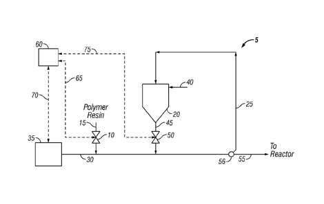
[0026] FIG. 1 illustrates an example embodiment of a seedbed storage system 5.
As illustrated,
polymer resin may be fed to valve 10 via flow line 15, such as from a resin
purge vessel or surge
vessel (not shown). The valve 10 may provide a continuous supply of the
polymer resin or it
may operate intermittently, thus providing a non-uniform feed of the polymer
resin. The valve
may be, for example, a rotary valve, a screw feeder, a belt feeder, a
vibrating feeder, or any other
suitable mechanism. From the valve 10, the polymer resin may be transferred to
the seedbed
container 20 via flow line 25. The polymer resin may be transferred to the
seedbed container 20
using a carrier fluid comprising an inert gas, such as nitrogen. The carrier
fluid may be supplied
via flow line 30 from pneumatic conveying equipment 35, which may include a
blower, for
example. The polymer resin may be stored in the seedbed container 20, for
example, under a
blanket or purge of inert gas, such as nitrogen, which may be supplied via
inert gas line 40
(shown as a blanket). Cooling jackets or another cooling mechanism may be used
to cool this
inert gas, in order to provide an additional cooling effect on the polymer
resin (not shown).
Cooling jackets or another cooling mechanism could also be used on any of the
resin conveying
lines, for example, anywhere on flow line 15 and/or flow line 25, to further
cool the resin while
it is being transferred and/or re-circulated.
[0027] At least a portion of the polymer resin in the seedbed container 20 may
be re-circulated
simultaneously with transfer of polymer resin via flow line 25. For re-
circulation, polymer resin
may be fed to flow line 25 via flow line 45. Valve 50 may be in flow line 45,
for example, to
regulate the flow of polymer resin from the seedbed container 20. The valve 50
may provide a
continuous supply of the polymer resin or it may operate intermittently, thus
providing a non-
6
CA 2885055 2020-03-19
CA 02885055 2015-03-13
WO 2014/055497 PCT/US2013/062838
uniform feed of the polymer resin. The valve 50 may be, for example, a rotary
valve, a screw
feeder, a belt feeder, a vibrating feeder, or any other suitable mechanism. In
flow line 25, the
polymer resin from the seedbed container 20 may be re-circulated with at least
a portion of fresh
polymer resin from flow line 15.
[0028] At least a portion of or all of the polymer resin from the seedbed
container 20 may also
be transferred to a polymerization reactor (not shown), for example, for use
as a seedbed. From
flow line 25, the polymer resin may be directed to the reactor via flow line
55. Valve 56 which
may be, for example, a rotary valve, a screw feeder, a belt feeder, a
vibrating feeder, or any other
suitable mechanism, may be used to divert the at least a portion of or all of
the polymer resin in
flow line 25 to flow line 55 for transfer to the polymerization reactor.
Polymer resin from the
seedbed container 20 may also be transferred, for example, from the container
to a polymer resin
storage vessel (not shown), subsequently transferred to a surge vessel (not
shown), and then
subsequently transferred to an extrusion operation (not shown) or other
downstream operation,
such as a packaging operation (not shown). Polymer resin from the seedbed
container 20 may
also be transferred directly to a downstream operation without these
intermediate steps.
[0029] One of ordinary skill in the art will appreciate that many variations
are possible. For
example, the process may comprise any of the following steps after
transferring resin into the
seedbed container 20, and these steps may take place in any order:
a. transferring resin from the seedbed container to a resin storage vessel;
b. transferring resin from the seedbed container to a resin surge vessel;
c. transferring resin from a resin storage vessel to a resin surge vessel;
d. transferring resin from a resin surge vessel to a resin storage vessel;
e. transferring resin from a resin storage vessel to a downstream operation;
and
f. transferring resin from said resin surge vessel to a downstream operation.
[0030] For example, the process may comprise at least one of steps a through f
above after
transferring resin into the seedbed container 20, at least two of steps a
through f above, at least
three of steps a through f above, or at least four of steps a through f above,
and the steps may be
completed in any order.
[0031] As illustrated in FIG. 1, a control system 60 may be associated with
the seedbed storage
system 5. The control system 60 may be associated with the storage system such
that it is used
to control the operation of at least one valve in FIG. 1, or the operation of
at least two valves, or
the operation of at least three valves. The control system 60 may comprise a
distributed control
system. The distributed control system may be any of a variety of different
control systems, and
may, for example, comprise at least one controller selected from the group
consisting of a multi-
7
CA 02885055 2015-03-13
WO 2014/055497 PCT/US2013/062838
loop controller and a programmable logic controller. As illustrated in FIG. 1,
the control system
60 may be coupled to the valve 10 via control line 65, to the pneumatic
conveying equipment 35
via control line 70, and to the valve 50 via control line 75. Thus, when
desired to transfer
polymer resin to the seedbed container 20, the control system 60 may, for
example, send a signal
to the valve 10, thereby causing the valve 10, which may be a rotary valve, to
feed the desired
amount of polymer resin from flow line 15 into flow line 25. When desired to
re-circulate
polymer resin in the seedbed container 20 or transfer polymer resin from the
seedbed container
20 to the polymerization reactor, the control system 60 may send a signal to
the valve 50,
thereby causing the valve 50, which may be a rotary valve, to feed the desired
amount of
polymer resin from the seedbed container into flow line 25. The control system
60 may also
send a signal to the pneumatic conveying equipment 35, which may include a
blower, to control
the flow of nitrogen in flow line 25.
[0032] Referring now to FIG. 2, a seedbed storage system 5 having three
seedbed storage
containers 20a, 20b, 20c is shown. As illustrated, polymer resin may be fed to
a vessel, such a
resin surge vessel 80, via flow line 85. The resin surge vessel 80 may include
a vent to
atmosphere (not shown). The polymer resin may be stored in the resin surge
vessel 80. The
polymer resin may be stored in the resin surge vessel 80, for example, under a
blanket or purge
of an inert gas, such as nitrogen, which may be supplied via inert gas line
90. The resin surge
vessel 80 may be used, for example, to enable a surge volume of polymer resin
to be maintained
for feeding downstream operations. For example, surge volume in the resin
surge vessel 80 may
compensate for short-term interruptions in supply of polymer resin from
upstream operations,
such as from the polymerization reactor or a product purge vessel (not shown).
A volume of
polymer resin in the resin surge vessel 80 may provide a continuous supply of
polymer resin to
downstream operations, allowing for upstream product transitions, downtime, or
other events
that may interrupt or necessitate stoppage of flow to the resin surge vessel
80.
[0033] As illustrated in FIG. 2, polymer resin may be removed from the resin
surge vessel 80
and fed to valve 95 via flow line 100. The valve 95 may be, for example, a
rotary valve, a screw
feeder, a belt feeder, a vibrating feeder, or any other suitable mechanism.
The valve 95 may
direct all or a portion of the polymer resin in flow line 100 to downstream
operations via flow
line 105. Downstream operations may include one or more of extrusion
operations, packaging
operations, combination of the polymer resin with one or more additional
additives to form
compositions that can be used in articles of manufacture, and any combination
thereof. The
valve 95 may direct all or a portion of the polymer resin to the seedbed
storage system 5 via
flow line 15.
8
81791191
[0034] As illustrated in FIG. 2, flow line 15 may further comprise valve 10,
which may be, for
example, a rotary valve, a screw feeder, a belt feeder, a vibrating feeder, or
any other suitable
mechanism. The valve 10 may provide a continuous supply of the polymer resin
or it may
operate intermittently, thus providing a non-uniform feed of the polymer
resin. From the valve
10, the polymer resin may be transferred to the seedbed containers 20a, 20b,
20c via flow line
25. As illustrated, valves 110b and 110c may be positioned in flow line 25.
Valves 110b and
110c may operate to selectively transfer polymer resin in flow line 25 to the
seedbed containers
20a, 20b, 20c. For example, embodiments may include operating the valves 110b
and 110c in
flow line 25 to separately transfer polymer resin to the seedbed containers
20a, 20b, 20c.
[0035] The polymer resin may be transferred to the seedbed containers 20a,
20b, 20c using a
carrier fluid comprising an inert gas, such as nitrogen. The carrier fluid may
be supplied via
flow line 30 from pneumatic conveying equipment 35, which may include a
blower, for
example. The polymer resin may be stored in the seedbed containers 20a, 20b,
20c, for
example, under a blanket or purge of an inert gas, such as nitrogen, which may
be supplied via
inert gas lines 40a, 40b, 40c. Cooling jackets or another cooling mechanism
may be used to
cool this inert gas, in order to provide an additional cooling effect on the
polymer resin (not
shown). Cooling jackets or another cooling mechanism could also be used on any
of the resin
conveying lines, for example, anywhere on flow line 15 and/or flow line 25, to
further cool the
resin while it is being transferred and/or re-circulated. The seedbed
containers 20a, 20b, 20c
may include vent lines 112a, 112b, 112c that may, for example, be coupled to
gas return line 146
for returning inert gas from the seedbed containers 20a, 20b, 20c to the
pneumatic conveying
equipment 35. In the seedbed containers 20a, 20b, 20c, the polymer resin may
be stored for
subsequent use, for example, as a seedbed in a polymerization reactor (not
shown).
[0036] At least a portion of the polymer resin in the seedbed containers 20a,
20b, 20c may be
re-circulated simultaneously with transfer of polymer resin via flow line 25.
Flow lines 45a,
45b, 45c may be used to withdraw polymer resin from one or more of the seedbed
containers
20a, 20b, 20c with valves 50a, 50b, 50c regulating the flow of polymer resin
from the seedbed
containers 20a, 20b, 20c. Valves 50a, 50b, 50c may be, for example, rotary
valves, screw feeders,
belt feeders, vibrating feeders, or any other suitable mechanisms. The valves
50a, 50b, 50c may
provide a continuous supply of the polymer resin or they may operate
intermittently, thus
providing a non-uniform feed of the polymer resin. In flow line 25, the
polymer resin may be
recirculated from the seedbed containers 20a, 20b, 20c with fresh polymer
resin from flow line
15.
9
CA 2885055 2020-03-19
CA 02885055 2015-03-13
WO 2014/055497 PCT/US2013/062838
[0037] At least a portion of or all of the polymer resin from the seedbed
container 20a, 20b, 20c
may be transferred to a polymerization reactor (not shown), for example, for
use as a seedbed.
From flow line 25, the polymer resin may be directed to the reactor via flow
line 55. Valve 56,
which may be, for example, a rotary valve, a screw feeder, a belt feeder, a
vibrating feeder, or any
other suitable mechanism, may be used to divert the at least a portion of or
all of the polymer
resin in flow line 25 to flow line 55 for transfer to the polymerization
reactor. Polymer resin
from the seedbed containers 20a, 20b, 20c may also be transferred, for
example, from the
container to a polymer resin storage vessel (not shown), subsequently
transferred to a surge
vessel (not shown), and then subsequently transferred to an extrusion
operation (not shown) or
other downstream operation, such as a packaging operation (not shown). Polymer
resin from the
seedbed containers 20a, 20b, 20c may also be transferred directly to a
downstream operation
without these intermediate steps.
[0038] One of ordinary skill in the art will appreciate that many variations
are possible. For
example, the process may comprise any of the following steps after
transferring resin into the
seedbed containers 20a, 20b, 20c, and these steps may take place in any order:
a. transferring resin from the seedbed containers to a resin storage vessel;
b. transferring resin from the seedbed containers to a resin surge vessel;
c. transferring resin from a resin storage vessel to a resin surge vessel;
d. transferring resin from a resin surge vessel to a resin storage vessel;
e. transferring resin from a resin storage vessel to a downstream operation;
and
f. transferring resin from said resin surge vessel to a downstream operation.
[0039] For example, the process may comprise at least one of steps a through f
above after
transferring resin into the seedbed containers 20a, 20b, 20c, at least two of
steps a through f
above, at least three of steps a through f above, or at least four of steps a
through f above, and
the steps may be completed in any order.
[0040] As illustrated in FIG. 2, the pneumatic conveying equipment may include
blowers 145a
and 145b. Inert gas in gas return line 146 from the seedbed containers 20a,
20b, 20c may be fed
to the blowers 145a and 145b. The pneumatic conveying equipment 35 may also
include inlet
heat exchanger 150 for cooling gas fed to the blowers 145a and 145b and outlet
heat exchanger
155 for cooling gas exiting the blowers 145a and 145b. One of ordinary skill
in the art will
appreciate that the pneumatic conveying equipment 35 may also include valves,
filters, pressure
sensors, and additional equipment not described in detail or illustrated
herein.
[0041] As will be readily appreciated by one of ordinary skill in the art, the
system as shown in
FIG. 2 may also comprise a control system (not shown) associated with the
seedbed storage
CA 02885055 2015-03-13
WO 2014/055497 PCT/US2013/062838
system 5. The control system may be, for example, similar in setup and
functionality to the
control system described with respect to FIG. I. For example, a control system
may be
associated with the storage system as shown in FIG. 2 such that it is used to
control the
operation of at least one valve in FIG. 2, or the operation of at least two
valves, or the operation
of at least three valves.
Polymerization Processes
[0042] As noted above, the systems and processes disclosed herein are useful
generally for
reducing the tendency of resins to sinter. One of ordinary skill in the art
will recognize that
these systems and processes may be usefully applied to many processes where
the resins
involved have the potential to sinter. Polymerization processes are described
below to
demonstrate the usefulness of the invention with respect to these processes,
but such description
should not be understood to be limiting.
[0043] Referring now to FIG. 3, an example of a polymerization system 245 with
a seedbed
storage system 5 is illustrated. In the illustrated embodiment, the
polymerization system 245
includes a polymerization reactor 250, a catalyst vessel 255, a discharge
vessel 260, a product
purge vessel 265, resin surge vessel 80, and a seedbed container 20.
[0044] As illustrated, the polymerization system 245 includes a catalyst
vessel 255 for
containing catalyst. The catalyst vessel 255 may be any of a variety of
different vessels suitable
for feeding catalyst to the polymerization reactor 250. In some embodiments,
the catalyst
generally should be stored in the catalyst vessel 255 at a pressure higher
than the polymerization
reactor 250 to facilitate transport of the catalyst to the polymerization
reactor 250. The catalyst
may be stored in the catalyst vessel 255, for example, under a blanket of an
inert gas, such as
nitrogen, which may be supplied via inert gas line 270. In some embodiments,
the catalyst
vessel 255 is a dry catalyst feeder vessel. Any type of polymerization
catalyst may be used,
including liquid-form catalysts, solid catalysts, and heterogeneous or
supported catalysts, among
others, and may be fed to the polymerization reactor 250 as a solution, a
slurry (liquid/solid
mixture), or as a solid. Examples of suitable catalysts will be described in
more detail below.
[0045] The catalyst may be transported from the catalyst vessel 255 through
catalyst injection
line 275 and into the polymerization reactor 250. As illustrated,
polymerization reactor 250
includes a reaction zone 280 and a velocity-reduction zone 285. The reaction
zone 280 includes
a fluidized bed comprising growing polymer particles, formed polymer
particles, and small
amounts of catalyst, fluidized by the continuous flow of fluid fed to the
polymerization reactor
250 via recycle line 290. The polymer product may be removed from the reaction
zone 280 via
product line 295. As illustrated, feed to the polymerization reactor 250 via
recycle line 290 may
11
CA 02885055 2015-03-13
WO 2014/055497 PCT/US2013/062838
contain both make-up fluid (e.g., fresh monomer and/or comonomer) from make-up
line 300 and
recycled fluid from the polymerization reactor 250. The feed stream may enter
the
polymerization reactor 250 via recycle line 290 through a distributor plate
305 at the bottom of
the reaction zone 280. The distributor plate 305 may aid in uniform
distribution of the feed
stream and also support the solid particles of the fluidized bed when the feed
stream is off.
Fluidization of the fluidized bed in the reaction zone 280 results, for
example, from the high rate
at which the feed stream flows into and through the polymerization reactor
250. The high rate of
the feed stream flow allows for the stream to suspend and mix the fluidized
bed in the reaction
zone 280 in a fluidized state.
[0046] The feed stream passes upward through the reaction zone 280, absorbing
heat generated
by the polymerization process. The portion of the feed stream that does not
react in the reaction
zone 280 leaves the reaction zone 280 and passes through the velocity-
reduction zone 285. In
the velocity-reduction zone 285, most polymer particles entrained within the
feed stream drop
back down into the reaction zone 280, thereby reducing the amount of polymer
particles that
may exit the polymerization reactor 250 via recycle line 290. In some
embodiments, after
exiting the polymerization reactor 250, a compressor 310 may compress fluid in
recycle line
290. As illustrated, a gas analyzer 315 may be used to analyze samples from
the recycle line
290 prior to its return to the polymerization reactor 250. In some
embodiments, after
compression, the stream may flow through heat exchanger 320 via recycle line
290, to remove
the heat generated by the polymerization process and cool the recycled stream.
In other
embodiments, the stream may flow through a heat exchanger, a liquid separation
process, and be
re-injected into the polymerization reactor as a liquid or partial-liquid
(embodiment not shown).
[0047] The polymer resin product may exit the polymerization reactor 250 via
product line 295.
The polymer resin product may be fed into discharge vessel 260 and then into
product purge
vessel 265. In the product purge vessel 265, an inert gas such as nitrogen
and/or steam may be
introduced via gas line 325, for example, to remove reactants and
terminate/prevent any
continuing polymerization. From the product purge vessel 265, the product
polymer resin may
be fed to the resin surge vessel 80 via flow line 85 and then fed to the
seedbed container 20.
Transfer of the polymer resin to the seedbed container 20 may be accomplished
using the
previously described techniques, for example. As desired, at least a portion
of the polymer resin
from the seedbed container 20 may be transferred to the polymerization reactor
250 via flow line
55.
[0048] While the preceding discussion of polymerization reactor 250 is
directed to a fluidized-
bed reactor for gas-phase polymerization, the present invention is not limited
to any particular
12
CA 02885055 2015-03-13
WO 2014/055497 PCT/US2013/062838
type of reactor. The resin storage systems described herein may be used with
any suitable
process for the polymerization of olefins, such as ethylene or propylene,
including any
suspension, solution, slurry, or gas phase process, using known equipment and
reaction
conditions. The polymerization process may be conducted over a wide range of
temperatures
and pressures. The temperatures, for example, may be in the range of from
about 50 C to about
280 C. In some embodiments, the temperature may be range from about 60 C to
about 280 C,
or from about 50 C to about 200 C, from about 60 C to about 120 C, or from
about 70 C to
about 100 C, or from about 80 C to about 95 C, wherein a desirable temperature
range may
include any combination of any upper limit with any lower limit described
herein. In some
embodiments, the reactor temperature may vary, for example, from about 30 C to
about 120 C,
or from about 60 C to about 115 C, or from about 70 C to about 110 C, or from
about 70 C to
about 95 C.
[0049] In general, the polymerization process may be a continuous gas-phase
process, such as a
fluidized-bed process. A fluidized-bed reactor may have a reaction zone and a
velocity-
reduction zone (i.e., disengagement zone). The reaction zone includes a bed of
growing polymer
particles, formed polymer particles, and a minor amount of catalyst particles
fluidized by the
continuous flow of the gaseous monomer and diluent to remove heat of
polymerization through
the reaction zone. Optionally, some of the recirculated gases may be cooled
and compressed to
form liquids that increase the heat removal capacity of the circulating gas
stream when
readmitted to the reaction zone. A suitable rate of gas flow may be readily
determined by simple
experiment. Makeup of gaseous monomer to the circulating gas stream is at a
rate equal to the
rate at which particulate polymer product and monomer associated therewith is
withdrawn from
the reactor, and the composition of the gas passing through the reactor is
adjusted to maintain an
essentially steady state gaseous composition within the reaction zone. The gas
leaving the
reaction zone is passed to the velocity-reduction zone where entrained
particles are removed.
Finer entrained particles and dust may be removed in a cyclone and/or fines
filter. The gas is
passed through a heat exchanger wherein the heat of polymerization is removed,
compressed in
a compressor and then returned to the reaction zone.
[0050] Useful gas-phase polymerization processes are described in, for
example, U.S. Patent
Nos. 3,709,853, 4,003,712, 4,011,382, 4,302,566, 4,543,399, 4,882,400,
5,352,749, and
5,541,270, as well as European publication EP-A-0 802 202. These patents
disclose gas-phase
polymerization processes wherein the polymerization medium is either
mechanically agitated or
fluidized by the continuous flow of the gaseous monomer and diluent.
13
CA 02885055 2015-03-13
WO 2014/055497 PCT/US2013/062838
[0051] The process described herein is suitable for the production of
homopolymers of olefins,
including ethylene, and/or copolymers, terpolymers, and the like, of olefins,
including polymers
comprising ethylene and at least one or more other olefins. The olefins may be
alpha-olefins.
The olefins, for example, may contain from 2 to 16 carbon atoms in one
embodiment. In other
embodiments, ethylene and a comonomer comprising from 3 to 12 carbon atoms, or
from 4 to
carbon atoms, or from 4 to 8 carbon atoms, may be used. In an embodiment, the
olefin is a
monomer selected from the group consisting of ethylene, propylene, and any
combination
thereof.
[0052] In embodiments, polyethylene may be prepared by the process disclosed
herein. Such
polyethylene may include homopolymers of ethylene and interpolymers of
ethylene and at least
one alpha-olefin wherein the ethylene content is at least about 50% by weight
of the total
monomers involved. Olefins that may be used as comonomers herein include,
propylene, 1-
butene, 1-pentene, 1-hexene, 1-heptene, 1-octene, 4-methylpent-1-ene, 1-
decene, 1-dodecene, 1-
hexadecene and the like. Also usable are polyenes such as 1,3-hexadiene, 1,4-
hexadiene,
cyclopentadiene, dicyclopentadiene, 4-vinylcyclohex-1-ene, 1,5-cyclooctadiene,
5 -vinylidene-2-
norbomene and 5-vinyl-2-norbomene, and olefins formed in situ in the
polymerization medium.
[0053] The content of the alpha-olefin copolymer incorporated into the polymer
may be no
greater than 500 mol% in total, or may be from 0.1 to 20 mol%. The term
"polyethylene" when
used herein is used generically to refer to any or all of the polymers
comprising ethylene
described above.
[0054] In other embodiments, propylene-based polymers may be prepared by
processes
disclosed herein. Such propylene-based polymers may include homopolymers of
propylene and
interpolymers of propylene and at least one alpha-olefin, wherein the
propylene content is at
least about 50% by weight of the total monomers involved. Comonomers that may
be used may
include ethylene, 1-butene, 1-pentene, 1-hexene, 1-heptene, 1-octene, 4-
methylpentene-1, 1-
decene, 1-dodecene, 1-hexadecene and the like. Also useful are polyenes such
as 1,3-hexadiene,
1,4-hexadiene, cyclopentadiene, dicyclopentadiene, 4-vinylcyclohexene-1, 1,5-
cyclooctadiene,
5-vinylidene-2-norbornene and 5-vinyl-2-norbornene, and olefins formed in situ
in the
polymerization medium. In one embodiment, the content of the alpha-olefin
comonomer
incorporated into a propylene-based polymer may be no greater than 49 mol % in
total, from 0.1
to 35 mol % in other embodiments.
[0055] Hydrogen gas is often used in olefin polymerization to control the
final properties of the
polyolefin. Increasing the concentration of hydrogen may increase the melt
flow index (MFI)
and/or melt index (MI) of the polyolefin generated. The MFI or MI can thus be
influenced by
14
CA 02885055 2015-03-13
WO 2014/055497 PCT/US2013/062838
the hydrogen concentration. The amount of hydrogen in the polymerization may
be expressed
as a mole ratio relative to the total polymerizable monomer, for example,
ethylene, or a blend of
ethylene and hexene or propylene. In an embodiment, the amount of hydrogen
used in the
polymerization processes is an amount sufficient to achieve the desired MFI or
MI of the final
polyolefin resin. Melt flow rate for polypropylene may be measured according
to ASTM D 1238
(230 C with 2.16 kg weight); melt index (I2) for polyethylene may be measured
according to
ASTM D 1238 (190 C with 2.16 kg weight).
[0056] Other gas-phase processes contemplated include series or multistage
polymerization
processes. For example, a staged reactor employing two or more reactors in
series may be used,
wherein one reactor may produce, for example, a high molecular weight
component and another
reactor may produce a low molecular weight component. In some embodiments, the
polyolefin
is produced using a staged gas phase reactor. Such polymerization systems are
described in, for
example, U.S. Patent Nos. 5,627,242, 5,665,818, and 5,677,375, and European
publications EP-
A-0 794 200, EP-B1-0 649 992, EP-A-0 802 202, and EP-B-634 421.
[0057] In one embodiment, the one or more reactors in a gas-phase or fluidized-
bed
polymerization process may have a pressure ranging from about 0.7 to about 70
bar (about 10 to
about 1,000 psia), or from about 14 to about 42 bar (about 200 to about 600
psia). In one
embodiment, the one or more reactors may have a temperature ranging from about
10 C to
about 150 C, or from about 40 C to about 125 C. In an embodiment, the reactor
temperature
may be operated at the highest feasible temperature taking into account the
sintering temperature
of the polymer within the reactor. In embodiments, the superficial gas
velocity in the one or
more reactors may range from about 0.2 to about 1.1 meters/second (about 0.7
to about 3.5
feet/second), or from about 0.3 to about 0.8 meters/second (about 1.0 to about
2.7 feet/second).
[0058] Some embodiments may be used with gas-phase polymerization systems, at
superatmospheric pressures in the range from 0.07 to 68.9 bar (1 to 1,000
psig), from 3.45 to
27.6 bar (50 to 400 psig) in some embodiments, from 6.89 to 24.1 bar (100 to
350 psig) in other
embodiments, and temperatures in the range from 30 to 130 C, or from 65 to 110
C, from 75 to
120 C in other embodiments, or from 80 to 120 C in further embodiments. In
some
embodiments, operating temperatures may be less than 112 C. In embodiments,
stirred or
fluidized-bed gas-phase polymerization systems may be used.
[0059] The polymerization process may be a continuous gas-phase process that
includes the
steps of: (a) introducing a recycle stream (including ethylene and alpha
olefin monomers) into
the reactor; (b) introducing the supported catalyst system; (c) withdrawing
the recycle stream
from the reactor; (d) cooling the recycle stream; (e) introducing into the
reactor additional
CA 02885055 2015-03-13
WO 2014/055497 PCT/US2013/062838
monomer(s) to replace the monomer(s) polymerized; (f) reintroducing the
recycle stream or a
portion thereof into the reactor; and (g) withdrawing a polymer product from
the reactor.
[0060] Processes disclosed herein may optionally use inert particulate
materials as fluidization
aids. These inert particulate materials can include carbon black, silica,
talc, and clays, as well as
inert polymeric materials. Carbon black, for example, has a primary particle
size of about 10 to
about 100 nanometers, an average size of aggregate of about 0.1 to about 30
microns, and a
specific surface area from about 30 to about 1500 m2/g. Silica has a primary
particle size of
about 5 to about 50 nanometers, an average size of aggregate of about 0.1 to
about 30 microns,
and a specific surface area from about 50 to about 500 m2/g. Clay, talc, and
polymeric materials
have an average particle size of about 0.01 to about 10 microns and a specific
surface area of
about 3 to 30 m2/g. These inert particulate materials may be used in amounts
ranging from
about 0.3 to about 80%, or from about 5 to about 50%, based on the weight of
the final product.
They are especially useful for the polymerization of sticky polymers as
disclosed in U.S. Patent
Nos. 4,994,534 and 5,304,588.
[0061] Chain transfer agents, promoters, scavenging agents and other additives
may be, and
often are, used in the polymerization processes disclosed herein. Chain
transfer agents are often
used to control polymer molecular weight. Examples of these compounds are
hydrogen and
metal alkyls of the general formula MxRy, where M is a Group 3-12 metal, x is
the oxidation
state of the metal, typically 1, 2, 3, 4, 5 or 6, each R is independently an
alkyl or aryl, and y is 0,
1, 2, 3, 4, 5, or 6. In some embodiments, a zinc alkyl is used, such as
diethyl zinc. Typical
promoters may include halogenated hydrocarbons such as CHC13, CFC13, CH3-CC13,
CF2C1-
CC13, and ethyltrichloroacetate. Such promoters are described in, for example,
U.S. Patent No.
4,988,783. Other organometallic compounds such as scavenging agents for
poisons may also be
used to increase catalyst activity. Examples of these compounds include metal
alkyls, such as
aluminum alkyls, for example, triisobutylaluminum. Some compounds may be used
to
neutralize static in the fluidized-bed reactor, others known as drivers rather
than antistatic
agents, may consistently force the static from positive to negative or from
negative to positive.
The use of these additives is well within the skill of those skilled in the
art. These additives may
be added to the circulation loops, riser, and/or downer separately or
independently from the
catalyst, or as part of the catalyst.
[0062] Continuity additives may also be used in the polymerization processes
disclosed herein,
for example, to control or potentially even eliminate reactor discontinuity
events, which in
general are a disruption in the continuous operation of a polymerization
reactor. As used herein,
the term "continuity additive or aid" and "antifoulant agent" refer to
compounds or mixtures of
16
CA 02885055 2015-03-13
WO 2014/055497 PCT/US2013/062838
compounds, such as solids or liquids, that are useful in gas-phase or slurry-
phase polymerization
processes to reduce or eliminate fouling of the reactor, where "fouling" may
be manifested by
any number of phenomena including sheeting of the reactor walls, plugging of
inlet and outlet
lines, formation of large agglomerates, or other forms of reactor upsets known
in the art. For
purposes here, the terms may be used interchangeably. In accordance with
embodiments, the
continuity additive may be used as a part of the catalyst system or introduced
directly into the
reactor independently of the catalyst system.
[0063] The specific continuity additive used may depend at least in part upon
the nature of the
static charge, the particular polymer being produced, and/or the particular
catalyst being used.
Non-limiting examples of continuity additives comprise fatty acid amines,
amide-hydrocarbon
or ethoxylated-amide compounds such as described as "surface modifiers" in WO
96/11961;
polyethylenimines having the structure --(CH2--CH2--NH)--, where n can be from
10 to 10,000;
polyetheramines; carboxylate compounds such as aryl-carboxylates and long
chain hydrocarbon
carboxylates, and fatty acid-metal complexes; alcohols, ethers, sulfate
compounds, metal oxides
and other compounds known in the art. Some specific examples of continuity
additives include
1,2-diether organic compounds, magnesium oxide, ARMOSTAT 310, ATMER 163, ATMER
AS-990, and other glycerol esters, IRGAST AS-990 and other ethoxylated amines
(e.g., N,N-
bis(2-hydroxyethyl)octadecylamine), alkyl sulfonates, and alkoxylated fatty
acid esters;
STADIS 450 and 425, KEROSTAT CE 4009 and KEROSTAT CE 5009, chromium N-
oleylanthranilate salts, calcium salts of a Medialan acid and di-tert-
butylphenol; POLYFLO 130,
TOLAD 511 (a-olefin-acrylonitrile copolymer and polymeric polyamine), EDENOL
D32,
aluminum stearate, aluminum distearate, sorbitan-monooleate, glycerol
monostearate, methyl
toluate, dimethyl maleate, dimethyl fumarate, triethylamine, 3,3-dipheny1-3-
(imidazol-1-y1)-
propin, and like compounds. In some embodiments, the continuity additive may
be a
polyethyleneimine commercially available from BASF Corporation under the trade
name
LUPASOL. In some embodiments, the continuity additive may be a polyetheramine
commercially available from Huntsman Corporation under the trade name
JEFFAMINE. In
some embodiments, the continuity additive is a metal carboxylate salt as
described, optionally,
with other compounds as described in this section. Any of the aforementioned
continuity
additives may be employed either alone or in combination as a continuity
additive.
[0064] In embodiments, the reactors disclosed herein are capable of producing
greater than 500
lbs of polymer resin per hour (227 kg/hr) to about 300,000 lbs/hr (136,000
kg/hr) or higher of
polymer, greater than 1000 lbs/hr (455 kg/hr), greater than 10,000 lbs/hr
(4540 kg/hr), greater
than 25,000 lbs/hr (11,300 kg/hr), greater than 35,000 lbs/hr (15,900 kg/hr),
greater than 50,000
17
CA 02885055 2015-03-13
WO 2014/055497 PCT/US2013/062838
lbs/hr (22,700 kg/hr), greater than 65,000 lbs/hr (29,000 kg/hr), or greater
than 180,000 lbs/hr
(81250 kg/hr).
[0065] The polymer resins produced can be used in a wide variety of products
and end-use
applications. The polymer resins may include, but are not limited to, linear
low density
polyethylene, low density polyethylenes, and high density polyethylenes, as
well as
polypropylenes of various densities. They include homopolymers, random
copolymers, and
impact copolymers.
[0066] The polymer resins, including ethylene- and propylene-based polymer
resins, have a
density, for example, in the range of from about 0.86 g/cm3 to about 0.97
g/cm3, from about 0.88
g/cm3 to about 0.965 g/cm3, or from about 0.900 g/cm3 to about 0.96 g/cm3.
[0067] The polymer resins produced by the process of the invention may have a
molecular
weight distribution, a weight average molecular weight to number average
molecular weight
(Mw/Mn), for example, of greater than 1.5 to about 15. In other embodiments,
the polymer
resins may have an Mw/Mn of greater than 2 to about 10 or greater than about
2.2 to less than
about 8.
[0068] The polymer resins of the present invention may have a melt index (M1)
or (12) as
measured by ASTM-D-1238-E (190 C/2.16kg), for example, in the range from 0.01
dg/min to
1000 dg/min. In other embodiments, the polymers may have a melt index of from
about 0.01
dg/min to about 100 dg/min or from about 0.1 dg/min to about 100 dg/min.
[0069] The polymer resins of the invention in an embodiment may have a melt
index ratio
(121/12) (121 is measured by ASTM-D-1238-F, [190 C/21.6kg]), for example, of
from 5 to 300. In
other embodiments, the polymers may have a melt index ratio of from about 10
to less than 250,
from 15 to 200, or from 20 to 180.
[0070] The polymer resins of the invention may be blended and/or coextn.tded
with any other
polymer. Non-limiting examples of other polymer resins include linear low
density
polyethylenes produced via conventional and/or single-site catalysis,
elastomers, plastomers,
high pressure low density polyethylene, high density polyethylenes,
polypropylenes, and the
like.
[0071] Polymer resins produced by the process of the invention and blends
thereof are useful
in such forming operations as film, pipe, sheet, and fiber extrusion and co-
extrusion as well as
blow molding, injection molding and rotary molding. Films include blown or
cast films formed
by coextrusion or by lamination useful as shrink film, cling film, stretch
film, sealing films,
oriented films, snack packaging, heavy duty bags, grocery sacks, baked and
frozen food
packaging, medical packaging, industrial liners, membranes, etc. in food-
contact and non-food
18
CA 02885055 2015-03-13
WO 2014/055497 PCT/US2013/062838
contact applications. Fibers may include, are not limited to, melt spinning,
solution spinning
and melt blown fiber operations for use in woven or non-woven form to make
filters, diaper
fabrics, medical garments, geotextiles, etc. Extruded articles may include
medical tubing, wire
and cable coatings, geomembranes, and pond liners. Molded articles include
single and multi-
layered constructions in the form of bottles, tanks, large hollow articles,
rigid food containers
and toys, etc.
Catalyst System
[0072] Any type of catalyst component may be used in the polymerization
processes described
herein, including liquid-form catalysts, solid catalysts, and heterogeneous or
supported catalysts,
among others, and may be fed to the reactor as a liquid, slurry (liquid/solid
mixture), or as a
solid (typically gas transported). Liquid-form catalysts useful in embodiments
disclosed herein
should be stable and sprayable or atomizable. These catalysts may be used
alone or in various
combinations or mixtures. For example, one or more liquid catalysts, one or
more solid
catalysts, one or more supported catalysts, or a mixture of a liquid catalyst
and/or a solid or
supported catalyst, or a mixture of solid and supported catalysts may be used.
These catalysts
may be used with co-catalysts, activators, and/or promoters well known in the
art. The term
"catalyst component," as used herein, is used interchangeably with the term
"catalyst," and
includes any compound or component, or combination of compounds and
components, that is
capable of increasing the rate of a chemical reaction, such as the
polymerization or
oligomerization of one or more olefins.
[0073] Examples of suitable catalysts include:
Ziegler-Natta catalysts, including titanium-based catalysts, such as those
described in
U.S. Patent Nos. 4,376,062 and 4,379,758. Ziegler-Natta catalysts are well
known in the art,
and typically are magnesium/titanium/electron donor complexes used in
conjunction with an
organoaluminum co-catalyst.
Chromium-based catalysts, including those described in U.S. Patent Nos.
3,709,853,
3,709,954, and 4,077,904, and others useful in the art.
Vanadium-based catalysts, such as vanadium oxychloride and vanadium
acetylacetonate, including those described in U.S. Patent No. 5,317,036, and
others useful in the
art.
Metallocene catalysts, including those described in U.S. Patent Nos. 6,933,258
and
6,894,131, and others useful in the art.
Cationic forms of metal halides, such as aluminum trihalides.
19
CA 02885055 2015-03-13
WO 2014/055497 PCT/US2013/062838
[0074] Cobalt catalysts and mixtures thereof, including those described in
U.S. Patent Nos.
4,472,559 and 4,182,814, and others useful in the art.
[0075] Nickel catalysts and mixtures thereof, including those described in
U.S. Patent Nos.
4,155,880 and 4,102,817, and others useful in the art.
[0076] Rare Earth metal catalysts, i.e., those containing a metal having an
atomic number in
the Periodic Table of 57 to 103, such as compounds of cerium, lanthanum,
praseodymium,
gadolinium and neodymium. Especially useful are carboxylates, alcoholates,
acetylacetonates,
halides (including ether and alcohol complexes of neodymium trichloride), and
allyl derivatives
of such metals. In various embodiments, neodymium compounds, particularly
neodymium
neodecanoate, octanoate, and versatate, are particularly useful rare earth
metal catalysts. Rare
earth catalysts may be used, for example, to polymerize butadiene or isoprene.
[0077] Any combination of one or more of the catalysts of the above.
[0078] In one or more embodiments, a "mixed" catalyst system or "multi-
catalyst" system may
be used. A mixed catalyst system includes at least one metallocene catalyst
component and at
least one non-metallocene component. The mixed catalyst system may be
described as a
bimetallic catalyst composition or a multi-catalyst composition. As used
herein, the terms
"bimetallic catalyst composition" and "bimetallic catalyst" include any
composition, mixture, or
system that includes two or more different catalyst components, each having
the same or
different metal group but having at least one different catalyst component,
for example, a
different ligand or general catalyst structure. Examples of useful bimetallic
catalysts can be
found in U.S. Patent Nos. 6,271,325, 6,300,438, and 6,417,304. The terms
"multi-catalyst
composition" and "multi-catalyst" include any composition, mixture, or system
that includes
two or more different catalyst components regardless of the metals. Therefore,
terms "bimetallic
catalyst composition," "bimetallic catalyst," "multi-catalyst composition,"
and "multi-catalyst"
will be collectively referred to herein as a "mixed catalyst system" unless
specifically noted
otherwise.
[0079] The catalyst system may comprise one or more activators. An activator
(also known as a
cocatalyst) is defined as any combination of reagents that increases the rate
at which a catalyst
oligomerizes or polymerizes unsaturated monomers, such as olefins.
100801 In one embodiment, alumoxanes activators may be utilized as an
activator in the catalyst
composition. Alumoxanes are generally oligomeric compounds containing --Al(R)--
0--
subunits, where R is an alkyl group. Examples of alumoxanes include
methylalumoxane
(MAO), modified methylalumoxane (MMAO), ethylalumoxane and isobutylalumoxane.
Alkylalumoxanes and modified alkylalumoxanes are suitable as catalyst
activators, particularly
CA 02885055 2015-03-13
WO 2014/055497 PCT/US2013/062838
when the abstractable ligand is a halide. Mixtures of different alumoxanes and
modified
alumoxanes may also be used. For further descriptions, see U.S. Pat. Nos.
4,665,208, 4,952,540,
5,041,584, 5,091,352, 5,206,199, 5,204,419, 4,874,734, 4,924,018, 4,908,463,
4,968,827,
5,329,032, 5,248,801, 5,235,081, 5,157,137, 5,103,031 and EP 0 561 476 Al, EP
0 279 586 Bl,
EP 0 516 476 A, EP 0 594 218 Al and WO 94/10180.
[0081] Aluminum alkyl or organoaluminum compounds may also be utilized as
activators (or
scavengers), including trimethylaluminum, triethylaluminum,
triisobutylaluminum, tri-n-
hexylaluminum, tri-n-octylaluminum and the like.
[0082] Ionizing or stoichiometric activators, neutral or ionic, such as tri (n-
butyl) ammonium
tetrakis (pentafluorophenyl) boron, a trisperfluorophenyl boron metalloid
precursor or a
trisperfluoronaphtyl boron metalloid precursor, polyhalogenated heteroborane
anions (see, WO
98/43983), boric acid (see, U.S. Pat. No. 5,942,459) or a combination thereof,
may also be used.
Neutral or ionic activators may be used alone or in combination with alumoxane
or modified
alumoxane activators.
[0083] Examples of neutral stoichiometric activators may include tri-
substituted boron,
tellurium, aluminum, gallium and indium or mixtures thereof The three
substituent groups may
be each independently selected from the group of alkyls, alkenyls, halogen,
substituted alkyls,
aryls, arylhalides, alkoxy and halides. In other embodiments, the three groups
are halogenated,
preferably fluorinated, aryl groups. In some embodiments, the neutral
stoichiometric activator is
selected from trisperfluorophenyl boron or trisperfluoronapthyl boron.
[0084] Exemplary ionic stoichiometric activator compounds are described in
European
publications EP-A-0 570 982, EP-A-0 520 732, EP-A-0 495 375, EP-B1-0 500 944,
EP-A-0 277
003 and EP-A-0 277 004, and U.S. Pat. Nos. 5,153,157, 5,198,401, 5,066,741,
5,206,197,
5,241,025, 5,384,299 and 5,502,124.
[0085] The described catalysts or catalyst systems, as noted above, may also
be combined with
one or more support materials or carriers. For example, in some embodiments,
the activator is
contacted with a support to form a supported activator wherein the activator
is deposited on,
contacted with, vaporized with, bonded to, or incorporated within, adsorbed or
absorbed in, or
on, a support or carrier. Any suitable material or method in the art for
forming a supported
catalyst may be used.
[0086] While compositions, methods, and processes arc described herein in
terms of
"comprising," "containing," "having," or "including" various components or
steps, the
compositions and methods can also "consist essentially of' or "consist of' the
various
components and steps. The phrases, unless otherwise specified, "consists
essentially of' and
21
81791191
"consisting essentially of" do not exclude the presence of other steps,
elements, or materials,
whether or not, specifically mentioned in this specification, so long as such
steps, elements, or
materials, do not affect the basic and novel charactcristics of the invention,
additionally, they do
not exclude impurities and variances normally associated with the elements and
materials used.
In the preceding description and the appended claims, the singular forms "a,"
"an" and "the"
include plural referents unless otherwise specified.
100871 For the sake of brevity, only certain ranges are explicitly disclosed
herein. However,
ranges from any lower limit may be combined with any upper limit to recite a
range not
explicitly recited, as well as, ranges from any lower limit may be combined
with any other lower
limit to recite a range not explicitly recited; in the same way, ranges from
any upper limit may
be combined with any other upper limit to recite a range not explicitly
recited.
[0088]
[0089] Therefore, the present invention is well adapted to attain the ends and
advantages
mentioned as well as those that are inherent therein. The particular
embodiments disclosed
above are illustrative only, as the present invention may be modified and
practiced in different
but equivalent manners apparent to those skilled in the art having the benefit
of the teachings
herein. Furthermore, no limitations are intended to the details of
construction or design herein
shown, other than as described in the claims below. It is therefore evident
that the particular
illustrative embodiments disclosed above may be altered or modified and all
such variations are
considered within the scope and spirit of the present invention. Although
individual
embodiments are discussed, the invention covers all combinations of all those
embodiments.
22
CA 2885055 2020-03-19