Note: Descriptions are shown in the official language in which they were submitted.
CA 02885082 2015-03-17
1
GAS TURBINE ROTOR
Field of the Invention
The present invention relates to a gas turbine engine and specifically to a
turbine
rotor having a sealing member for shielding and cooling the rotor disc faces
and
drive arms with dedicated cooler air bled from some engine compressor stage.
Prior Art
It is well known that the efficiency and output of a gas turbine engine can be
increased by increasing the operating temperature of the turbine.
Nevertheless, as
a practical matter, the turbine operating temperature is limited by the high
temperature capabilities of turbine elements. Some increase in efficiency and
output has been obtained by the development and use of new materials capable
of withstanding higher temperatures. Even these new materials are not,
however,
generally capable of withstanding the extremely high temperature desired in
modem gas turbines. Consequently, various heat shield arrangements have been
used for maintaining the structural elements of the turbine at temperatures at
which their materials have adequate strength to resist loads imposed during
operation. These heat shield arrangements are used to shield the rotor discs
and
the interconnecting rotor structure from the high temperature combustion
products
driving the turbine and to direct cooling air to the structural elements. The
following
documents may be cited as antecedents: US3056579A, US3343806A,
US4088422A, US4526508A, US4730982A, US5816776A, US628371261,
U56655920E32, US2002187046A1, US2012060507A1 y US2013039760A1.
This cooling is generally accomplished by means of pressurised air bled from
the
compressor. Since engine performance is reduced by cooling air off-take, it is
imperative that the cooling air is used effectively, lest the decrease in
efficiency
caused by extraction of the air is greater than the increase resulting from
the
higher turbine operating temperature. This means that such heat shield
arrangements must be efficient from the standpoint of minimizing the quantity
of
cooling air required to cool satisfactory the structural elements.
The complexity of the geometry of the heat shield and disc elements and the
broad range of temperatures and temperature gradients involved in the
environment surrounding these elements make sealing difficult to achieve.
Classical heat shield arrangements rely on achieving an effective sealing of
the
cooling passage formed between the heat shield and the disc. Cooling
performance is very sensitive to the area of this leakage as an increase in
leakage
flow implies a reduction in available cooling flow.
BRIEF SUMMARY OF THE INVENTION
A turbine section of a gas turbine engine includes stator and rotor rows. Each
rotor
row has a plurality of blades connected to a rotor disc at blade attachments.
Each
stator row has a plurality of vanes attached to a seal carrier which supports
an
abradable seal land. The rotor disc includes drive arms which typically extend
forward and rearward from the disc and include connecting flanges at their
edge.
A heat shield includes a connecting flange in its front section attached to
adjacent
disc flanges and has at least one knife edge member to form a labyrinth seal
with
the stator seal land. The heat shield extends rearward from the flange region
to
CA 02885082 2015-03-17
2
surround the shape of the disc and the disc drive arm but leaving a
predetermined
annular space between the heat shield and the disc or disc drive arm which
defines the heat shield cooling flow passage.
In a preferred embodiment of the present application, the disc cooling flow
from
the turbine internal cavity is directed to recessions in the connecting
flanges which
communicate the internal turbine cavity with the heat shield cooling flow
passage.
The disc cooling flow protects the disc and the front disc drive arm against
hot gas
ingestion from the main engine gas path. The amount of disc cooling flow is
controlled in the preferred embodiment by slots in the heat shield spigot
along the
heat shield cooling flow passage, which act as heat shield flow restrictors.
A portion of the disc cooling flow is directed to bucket grooves beneath each
of the
blade roots in the blade attachment region, thereby cooling disc rim, and is
controlled in the preferred embodiment by orifices in blade retention lock
plates
situated at the end of such bucket grooves, which act as bucket groove flow
restrictors.
The remaining portion of the disc cooling flow is exhausted through a rim gap
formed by the heat shield rim edge and the disc front face thereby cooling the
disc
rim front face and the blade shank cavity over the disc outer radius.
The area of the rim gap is set at least three times larger than the area of
the heat
shield flow restrictors and also than the area of the lock plate discharge
orifices
which implies the pressure in the rim cavity is practically the same as the
pressure
in the external cavity at the exit of the rim and that variations in rim gap
area will
not affect either disc cooling flow or bucket groove cooling flow.
The area of the heat shield flow restrictors is set to provide a predetermined
larger
amount of flow than the area of the bucket groove flow restrictors,
considering the
worst combination of extremes of restrictor area tolerances which consists in
minimum tolerance area of heat shield flow restrictors and maximum tolerance
area of bucket groove flow restrictors. This combination ensures rim gap
cooling
outflow at all times preventing hot gas ingestion into the heat shield cooling
flow
passage.
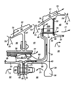
BRIEF DESCRIPTION OF THE DRAWINGS
FIG. 1 is a schematic cross-sectional view of an axial flow gas turbine
engine.
FIG. 2 is a schematic cross-sectional view of a portion of a turbine section
of an
axial flow gas turbine engine including one turbine stage and a heat shield of
the
invention.
FIG. 3 is an exploded perspective view of a circumferential portion of the
heat
shield and two adjacent disc flanges illustrating a cooling feed through a
flow non-
restrictive large area recession in the heat shield flange and heat shield
cooling
flow restrictors situated in the heat shield rear extension.
FIG. 4 is an exploded perspective view of an alternative embodiment to that
shown in FIG. 3 illustrating a cooling feed through heat shield flow
restrictors
CA 02885082 2015-03-17
3
situated in the heat shield flange and a flow non-restrictive large area slot
in the
heat shield rear extension.
FIG. 5 is an exploded perspective view of an alternative embodiment to that
shown in FIG. 3 illustrating a cooling feed through heat shield flow
restrictors
situated in the rear disc flange and a flow non-restrictive large area slot in
the heat
shield rear extension.
In these figures, reference is made to the following set of elements:
10. gas turbine engine
11. intake
12. propulsive fan
13. intermediate pressure compressor
14. high pressure compressor
15. combustion equipment
16. high pressure turbine
17. intermediate pressure turbine
18. low pressure turbine
19. exhaust nozzle
20. rotor disc
21. rotor row
22. stator row
23. blades
24. blade platforms
25A. blade shanks
25B. blade attachments
26. vanes
27. vane platforms
28. seal carrier
29. seal land
30. disc cob
31. disc web
32. disc rim
33. lock plates
34. bucket grooves
40. front stator well
41. rear stator well
43. heat shield cooling flow passage
44. turbine internal cavity
45. cooling feed slots
46. disc rim front cavity
50. front disc drive arm
51. rear disc drive arm
52. front disc connecting flange
53. rear disc connecting flange
60. heat shield
61. heat shield connecting flange
62. nut and bolt combinations
63. knife edge members
CA 02885082 2015-03-17
4
70. main engine gas path
71. disc cooling flow
73. front disc hot gas ingestion
74. front disc rim sealing outflow
75. bucket groove cooling flow
76. heat shield rim leakage
77. labyrinth seal leakage
78. rear disc hot gas ingestion
79. rear disc rim sealing outflow
80. bucket groove flow restrictors
81. heat shield rim gap
82. heat shield flow restrictors
84. front heat shield spigot
85. front disc spigot
86. rear heat shield spigot
87. rear disc spigot
89. rear heat shield spigot recess
DETAILED DESCRIPTION OF THE INVENTION
FIG. 1 is a view of a gas turbine engine generally indicated at 10 and
comprises,
in axial flow series, an air intake //, a propulsive fan /2, an intermediate
pressure
compressor /3, a high pressure compressor /4, combustion equipment 15, a high
pressure turbine /6, an intermediate pressure turbine /7, a low pressure
turbine
18 and an exhaust nozzle /9.
The gas turbine engine 10 works in a conventional manner so that air entering
the
intake 1/ is accelerated by the fan /2 which produces two air flows: a first
air flow
into the intermediate pressure compressor /3 and a second air flow which
provides propulsive thrust. The intermediate pressure compressor compresses
the air flow directed into it before delivering that air to the high pressure
compressor /4 where further compression takes place.
The compressed air exhausted from the high pressure compressor 14 is directed
into the combustion equipment /5 where it is mixed with fuel and the mixture
combusted. The resultant hot combustion products then expand through, and
thereby drive, the high, intermediate and low pressure turbines 16, 17 and 18
before being exhausted through the nozzle /9 to provide additional propulsive
thrust. The high, intermediate and low pressure turbines, 16, 17 and 18
respectively, drive the high and intermediate pressure compressors 14 and 13,
and the fan 12 by suitable interconnecting shafts.
FIG. 2 is an enlarged schematic view of the low pressure turbine 18 shown in
FIG.
1, which includes one intermediate stage comprising a stator row 22 and a
rotor
row 2/.
The rotor row 2/ includes a plurality of blades 23 extending radially
outwardly from
circumferentially extending blade platforms 24 and connecting to a
circumferentially extending rotor disc 20 at blade attachments 25B of typical
fir-
tree or dove-tail shaped style. Blade platforms 24 are connected in their root
to
CA 02885082 2015-03-17
blade attachments 25B through radially extending circumferentially
discontinuous
blade shanks 25A.
The stator row 22 includes a plurality of vanes 26 extending radially
outwardly
from circumferentially extending vane platforms 27. A circumferentially
extending
seal carrier 28 is attached to vane platforms 27 by nut and bolt combinations.
A
circumferentially extending seal land 29, formed of an abradable material,
typically
of honeycomb type, is attached to the seal carrier 28.
The rotor disc 20 includes a disc cob 30 in the region of the bore of the
disc, a disc
rim 32 and a disc web 31 connecting the cob and the rim sections. The rotor
disc
20 includes a front disc drive arm 50 which extends axially forward from the
disc
web 31 and a rear disc drive arm 51 which extends axially rearward from the
disc
rim 32. A radially inwardly extending front disc connecting flange 52 and a
rear
disc connecting flange 53 are located at the edge of the front disc drive arm
50
and the rear disc drive arm 51 respectively. FIG.2 shows the rear disc drive
arm
51 partially for the rotor row shown, the remaining part being shown from the
preceding rotor row in the turbine. Likewise, the rear disc connecting flange
is
shown from the previous rotor row.
A circumferentially extending rotating heat shield 60 includes an inwardly
radially
extending heat shield connecting flange 61 in its front section which can be
attached, by nut and bolt combinations 62, intermediate adjacent the front
disc
connecting flange 52 and the rear disc connecting flange 53 of the disc from
the
previous turbine stage. At least one knife edge members 63 extend outwardly
and
circumferentially about the front connecting flange section of the heat shield
60
and is axially and radially oriented to form a labyrinth seal with the seal
land 29.
The heat shield 60 extends from its front connecting flange region axially
rearward
and then curves to extend radially outward to surround the shape of the rotor
disc
20, forming an annular heat shield cooling flow passage 43 between the heat
shield inboard face and the front disc drive arm 50, disc web 31, disc rim 32
and
rotor blade attachments 25B.
A plurality of lock plates 33 are mounted circumferentially aligned, each
covering
at least one rotor blade sections, and extend radially outwardly to engage the
blade platforms 24 and radially inwardly to engage the disc rim 32. The lock
plates
provide axial retention of the rotor blades, restricting the axial movements
of the
blade platforms 24 relative to the disc rim 32, and also form a physical
barrier in
order to prevent leakage from a higher pressure fluid in annular rear stator
well 41
upstream of the front face of rotor disc 20 to annular front stator well 40
downstream of the rear face of rotor disc 20 through the cavities formed
between
adjacent circumferentially discontinuous blade shanks 25A and through the gaps
formed between adjacent lock plates 33.
In the embodiment shown schematically in FIG. 2, a disc cooling flow 71 from
an
annular turbine internal cavity 44 wets and cools the inboard faces of the
rotor disc
20 before being directed to circumferentially discontinuous and radially
continuous
cooling feed slots 45, recessed between adjacent bolts in the scalloped heat
CA 02885082 2015-03-17
6
shield connecting flange 61, which put the turbine internal cavity 44 in fluid
communication with the heat shield cooling flow passage 43.
The disc cooling flow 7/ flows through the heat shield cooling flow passage 43
and protects the front disc drive arm 50, disc web 3/ and disc rim 32 against
the
hot temperature gases from labyrinth seal leakage 77 and front disc hot gas
ingestion 73 from main engine gas path 70.
In the embodiment shown schematically in FIG. 2, the amount of the disc
cooling
flow 71 is controlled by the area of heat shield flow restrictors 82. The disc
cooling
flow 71 splits into two flows when it reaches disc rim front cavity 46, a heat
shield
rim leakage 76 through a heat shield rim gap 8/ and bucket groove cooling flow
75 through bucket grooves 34.
In the turbine rim gap formed by the rear end of vane platforms 27 and the
front
end of blade platforms 24, an inwardly flowing front disc hot gas ingestion 73
and
an outwardly flowing front disc rim sealing flow 74 concur at different
circumferential positions and are induced by the circumferential aerodynamic
pressure profile of the main engine gas path 70. Likewise, in the turbine rim
gap
formed by the rear end of blade platform 24 and the front end of vane platform
27,
an inwardly flowing rear disc hot gas ingestion 78 and an outwardly flowing
rear
disc rim sealing flow 79 concur at different circumferential positions and are
induced by the circumferential aerodynamic pressure profile of the main engine
gas path 70.
Labyrinth seal leakage 77 is driven by the ratio of pressures between the
upstream front stator well 40 and the downstream rear stator well 41, the
pressure
and temperature prevailing at the upstream front stator well 40 and the radial
gap
between the knife edge members 63 and the seal land 29. The net flow in the
turbine rim downstream of the vane platform 27 between the inflowing front
disc
hot gas ingestion 73 and the outwardly flowing front disc rim sealing outflow
74 is
driven by the flow balance of the labyrinth seal leakage 77 and any other
leakage
that could exist into or from the rear stator well 41. The net flow in the
turbine rim
downstream of the blade platform 24 between the inflowing rear disc hot gas
ingestion 78 and the outwardly flowing rear disc rim sealing outflow 79 is
driven by
the flow balance of the bucket groove cooling flow 75, the labyrinth seal
leakage
77 and any other leakage that could exist into or from the front stator well
40.
Small amounts of the bucket groove cooling flow 75, a large amount of the
labyrinth seal leakage 77 or a combination of both effects may lead to null
outwardly flowing rear disc rim sealing outflow 79 with solely rear disc hot
gas
ingestion 78 into the front stator well 40 which brings about an undesirable
increase in temperature of the gas inside the front stator well 40.
The bucket groove cooling flow 75 is a portion of the disc cooling flow 71
that
flows through the bucket grooves 34 in the disc rim 32, beneath each of the
blade
roots in the region of the blade attachments 258, thereby cooling disc rim 32.
The
amount of the bucket groove cooling flow 75 is controlled by bucket groove
flow
restrictors 80 machined in the lock plates 33.
CA 02885082 2015-03-17
7
The heat shield rim leakage 76 is the remaining portion of the disc cooling
flow 7/
following extraction of the bucket groove cooling flow 75 and is radially
exhausted
through the circumferentially extending heat shield rim gap 81 formed by the
radially outer edge inboard face of the heat shield 60 and the front face of
the rotor
disc 20 in the region of the blade attachments 25B. The area of the heat
shield rim
gap 81 is set at least three times larger than the area of the heat shield
flow
restrictors 82 and also than the area of the bucket groove flow restrictors 80
which
implies the pressure in the disc rim front cavity 46 is practically the same
as the
pressure in the rear stator well 41 at the exit of the rim gap 81.
The amount of the disc cooling flow 71 is thus dictated by the area of the
heat
shield flow restrictors 82, the pressure and temperature in the upstream
turbine
internal cavity 44 and the pressure in the downstream disc rim front cavity
46. The
bucket groove cooling flow 75 is dictated by the area of the bucket groove
flow
restrictors 80, the pressure and temperature in the upstream disc rim front
cavity
46 and the pressure in the downstream front stator well 40.
The area of the heat shield flow restrictors 82 is set to provide a
predetermined
higher flow than the area of the bucket groove flow restrictors 80 considering
that
the pressure in the disc rim front cavity 46 is practically at the same level
than the
pressure in the rear stator well 41 and that the area of the heat shield flow
restrictors 82 and the bucket groove flow restrictors 80 could potentially be
at their
worst combination of extreme values of tolerances which consists in minimum
tolerance area of the heat shield flow restrictors 82 and maximum tolerance
area
of the bucket groove flow restrictors 80. This ensures that the heat shield
rim
leakage 76 always flows radially outwards, prevenfing that the hot temperature
gas mixture from the rear stator well 41, consisting of the front disc hot gas
ingestion 73 and the labyrinth seal leakage 77, flows into the heat shield
cooling
flow passage 43, and also ensures that the heat shield rim leakage 76 cools
the
rotor disc 20 front face about the rotor blade attachments 25B. Any variations
in
the area of the heat shield rim gap 81 due to movements of the rotor disc 20
relative to the heat shield 60, induced by thermal or mechanical loads, do not
affect the disc cooling flow 71, the heat shield rim leakage 76 or the bucket
groove
cooling flow 75 provided that the area of the heat shield rim gap 81 is such
that it
maintains substantially larger than the area of the heat shield flow
restrictors 82
and the area of the bucket groove flow restrictors 80 at any of the operating
condition. If an insufficient area was unintendedly incurred due to a partial
or
complete closure in any extreme situation, the disc cooling flow 71 would tend
to
equal the bucket groove cooling flow 75 by altering the disc rim front cavity
46
pressure to a higher level than the pressure in the rear stator well 41 which
would
anyhow prevent hot gas ingestion into the disc rim front cavity 46 at any
time.
Some amount of flow is always required to satisfy leakage through the blade
platforms 24 to the main engine gas path 70 and leakage through the lock
plates
33 to the front stator well 40. Although these leakage are typically satisfied
by the
labyrinth seal leakage 77 and the rear disc hot gas ingestion 78, the heat
shield
rim leakage 76 from the heat shield is prone to be dragged and fill the
cavities
between adjacent blade shanks 25A after it is radially exhausted through the
heat
shield rim gap 81 which contributes to cool the radially outer disc rim
surface
CA 02885082 2015-03-17
8
exposed to the blade shank cavity fluid conditions between adjacent blade
attachments 258.
FIG. 3 is an exploded perspective view of circumferential and axial portions
of the
heat shield 60 and two adjacent discs, illustrating in greater detail the
preferred
embodiment shown in FIG. 2 in the region of the disc cooling feed. The disc
cooling flow 71 is fed through cooling feed slots 45, consisting in non-
restrictive to
flow large area recessions in the heat shield connecting flange 61 axially
bounded
by the front disc connecting flange 52 and the rear disc connecting flange 53,
and
then passes through the heat shield flow restrictors 82, consisting in a set
of axial
slots circumferentially distributed along a circumferentially extending rear
heat
shield spigot 86 sitting on a circumferentially extending rear disc spigot 87
in the
front disc drive arm 50. Leakage from disc cooling flow 71 is prevented by a
circumferentially extending front heat shield spigot 84 sitting on a
circumferentially
extending front disc spigot 85 in the rear disc drive arm 51.
'FIG. 4 is an exploded perspective view of circumferential and axial portions
of the
heat shield 60 and two adjacent discs, illustrating in greater detail an
alternative
embodiment to the embodiment shown in FIG. 3 in the region of the disc cooling
feed. The disc cooling flow 71 is fed through the heat shield flow restrictors
82,
which include a set of radial slots circumferentially distributed along the
rearward
side of the heat shield connecting flange 61 and axially bounded by the front
disc
connecting flange 52, and then passes through a rear heat shield spigot recess
89, consisting in a set of non-restrictive to flow large area axial slots
circumferentially distributed along a circumferentially extending rear heat
shield
spigot 86 sitting on a circumferentially extending rear disc spigot 87 in the
front
disc drive arm 50. Leakage from disc cooling flow 71 is prevented by a
circumferentially extending front heat shield spigot 84 sitting on a
circumferentially
extending front disc spigot 85 in the rear disc drive arm 51.
FIG. 5 is an exploded perspective view of circumferential and axial portions
of the
heat shield 60 and two adjacent discs, illustrating in greater detail an
alternative
embodiment to the embodiment shown in FIG. 3 in the region of the disc cooling
feed. The disc cooling flow 71 is fed through the heat shield flow restrictors
82,
which include a set of radial slots circumferentially distributed along the
forward
side of the front disc connecting flange 52 and axially bounded by the heat
shield
connecting flange 61, and then passes through a rear heat shield spigot recess
89, consisting in a set of non-restrictive to flow large area axial slots
circumferentially distributed along a circumferentially extending rear heat
shield
spigot 86 sitting on a circumferentially extending rear disc spigot 87 in the
front
disc drive arm 50. Leakage from disc cooling flow 71 is prevented by a
circumferentially extending front heat shield spigot 84 sitting on a
circumferentially
extending front disc spigot 85 in the rear disc drive arm 51.
While this invention has been described with respect to a preferred
embodiment, it
will be understood by those skilled in the art that various changes and
modifications may be done without departing from the spirit and scope of this
application as set forth in the following claims.