Note: Descriptions are shown in the official language in which they were submitted.
CA 02885236 2015-03-16
WO 2014/043779
PCT/CA2012/000862
1
RETAINING MEMBRANE ON A STRUCTURE
Technical Field
[0001] The present invention relates to membrane covered
structures and,
more specifically, structures covered by interconnected sections of membrane.
Background
[0002] Membrane covered structures are usually large metal
structures
covered by flexible material placed thereover. These membrane covered
structures
usually serve as a shelter for human activities or for storing quantities of
crops,
engines, other utilities, etc. The nature of the flexible material makes it
more prone to
wear and tear over time. Installing or repairing the membrane of a membrane
covered
building is cumbersome as it sometimes requires affecting the structure itself
in order to
install a new section of membrane or replacing a section of membrane.
[0003] The present invention addresses the above issue.
Summary
[0004] A first aspect of the present invention is directed to a
system for
retaining membrane on a structure. The system comprises a connecting member, a
truss of the structure and fastening mechanism. The connecting member
comprises at
least one radial channel for receiving a first guiding strip of a first
membrane sheet
having the first guiding strip and a second guiding strip. The fastening
mechanism is for
adjusting tension in the first sheet by controlling depth at which a
connecting member is
maintained within a top channel on the truss.
[0005] The first guiding strip of the first sheet may be located
on a lateral
portion of the first sheet. The second guiding strip of the first sheet may be
located on
an opposite lateral portion of the first sheet. The guiding strips may be
flexible.
[0006] The top channel may be formed by an upper surface of the
truss or may
be maintained over the upper surface of the truss (i.e., an additional member
forms the
top channel and is maintained over the truss by the fastening mechanism or by
other
means).
[0007] The first sheet may be made of fabric.
CA 02885236 2015-03-16
WO 2014/043779 PCT/CA2012/000862
2
[0008] The connecting member may be formed by multiple sub-
connecting
members within the top channel of the truss.
[0009] The connecting member may comprise a second radial
channel. A first
guiding strip of a second sheet of membrane may be inserted in the second
radial
channel.
[0010] The connecting member may be extruded. The connecting
member may
be made of aluminum, an aluminum alloy or a polymer. The connecting member may
comprise a bottom channel and the fastening mechanism may comprise screws and
nuts. The bottom channel may be adapted to receive screw heads. The screws may
be
bolted into the top channel of the truss.
[0011] The tension may be adjusted by applying a torque to the
bolted screws
maintaining the connecting member into the top channel.
[0012] The truss may be made of steel, which may further be
galvanized steel.
[0013] A second aspect of the present invention is directed to a
method for
installation of membrane sheets over a structure. The method comprises
inserting a
first guiding strip located on a lateral portion of a first membrane sheet
into a first radial
channel of a first connecting member. The method further comprises inserting a
first
guiding strip located on a lateral portion of a second membrane sheet into a
second
radial channel of the first connecting member. The method further comprises
inserting
the first connecting member into a first top channel of a first truss of the
structure for
receiving the first connecting member and fastening the first connecting
member in the
first top channel of the first truss. The tension applied in the first sheet
is related to a
first depth at which the first connecting member is maintained in the first
top channel of
the first truss.
[0014] The method for installation of membrane sheets over a structure may
further comprise inserting a second guiding strip located on an opposite
lateral portion
of the first membrane sheet into a first radial channel of a second connecting
member.
The method may further comprise inserting the second connecting member into a
second top channel of a second truss of the structure for receiving the second
connecting member. The method may further comprise fastening the second
connecting member in the second top channel of the second truss. The tension
applied
in the first sheet is related to both the first depth at which the first
connecting member is
maintained in the first top channel of the first truss and a second depth at
which the
CA 02885236 2015-03-16
WO 2014/043779 PCT/CA2012/000862
3
second connecting member is maintained in the second top channel of the second
truss.
[0015] The method for installation of membrane sheets over a
structure may
further comprise fastening the first connecting member to the first top
channel of the
first truss by bolting screws. The screw heads of the screws may be received
in a first
bottom channel of the first connecting member. The screws may then be bolted
into the
first top channel of the first truss.
[0016] The method for installation of membrane sheets over a
structure may
further comprise fastening the second connecting member to the second top
channel of
the second truss by bolting screws. Screw heads of the screws may be received
in a
second bottom channel of the second connecting member. The screws may then be
bolted into the second top channel of the second truss.
[0017] A third aspect of the present invention is directed to a
method for
replacing a membrane sheet on a membrane covered structure. The membrane sheet
to be replaced is under tension and inserted into a first connecting member
fastened in
a first top channel of a first truss and a second connecting member fastened
in a
second top channel of a second truss. The method comprises unfastening, at
least
partially, the first connecting member from the first top channel of the first
truss. The
membrane sheet to be replaced has a first guiding strip, located on a lateral
portion of
the first sheet, the first guiding strip inserted into a first radial channel
of the first
connecting member. The method further comprises removing the first guiding
strip of
the sheet to be replaced from the first radial channel of the first connecting
member.
The method further comprises removing a second guiding strip, located on an
opposite
lateral portion of the membrane sheet to be replaced, from a first radial
channel of the
second connecting member.
[0018] The method for replacing a membrane sheet to be replaced
on a
membrane covered structure, where the unfastening may further comprise
unbolting
screws which are bolted into the first truss. Screw heads of the screws may be
received in a first bottom channel of the first connecting member.
[0019] The method for replacing a membrane sheet to be replaced on a
membrane covered structure may further comprise unfastening the second
connecting
member from the second top channel of the second truss.
CA 02885236 2015-03-16
WO 2014/043779 PCT/CA2012/000862
4
[0020] The method for replacing a membrane sheet to be replaced
on a
membrane covered structure, where the unfastening may further comprise
unbolting
screws which are bolted into the second truss. Screw heads of the screws may
be
received in a second bottom channel of the second connecting member.
[0021] The method for replacing a membrane sheet to be replaced on a
membrane covered structure may further comprise inserting a first guiding
strip located
on a lateral portion of a replacing membrane sheet into the first radial
channel of the
first connecting member. The method may further comprise inserting a second
guiding
strip located on an opposite lateral portion of the replacing membrane sheet
into the
first radial channel of the second connecting member. The method may further
comprise fastening the first connecting member in the first top channel of the
first truss.
A second tension applied in the replacing sheet may be related to a depth at
which the
first connecting member is maintained in the first top channel of the first
truss.
[0022] The method for replacing a membrane sheet to be replaced
on a
membrane covered structure may further comprise fastening the second
connecting
member in the second top channel of the second truss. The second tension
applied in
the replacing sheet may be related to the depth at which the first connecting
member is
maintained in the first top channel of the first truss and a depth at which
the second
connecting member is maintained in the second top channel of the second truss.
Brief description of the drawings
[0023] Further features and exemplary advantages of the present
invention will
become apparent from the following detailed description, taken in conjunction
with the
appended drawings, in which:
[0024] Figure 1 is a perspective view of an exemplary membrane
covered
structure in accordance with the teachings of the present invention;
[0025] Figure 2A, Figure 2B and Figure 2C herein referred to
concurrently as
Figure 2 are views from above of a cross-section of an exemplary system for
retaining
membrane on a structure in accordance with the teachings of the present
invention;
[0026] Figure 3 is a view from above of a cross-section of an
exemplary system
for retaining membrane on a structure in accordance with the teachings of the
present
invention;
.
PCT/CA2012/000862
CA 02885236 2015-03-16
17 January 2014 17-01-2014
I CI LG1 IL rlIJIJIIµoGILIVI I
[0027] Figure 4 is a view from above of a cross-section of an
exemplary system
for retaining membrane on a structure in accordance with the teachings of the
present
invention;
[0028] Figure 5 is a view from above of a cross-section of an
exemplary system
5 for retaining membrane on a structure in accordance with the teachings of
the present
invention;
[0029] Figure 6 is a flowchart of an exemplary method for
installation of
membrane sheets over a structure in accordance with the teachings of the
present
invention; and
[0030] Figure 7 is a flowchart of an exemplary method for replacing a
membrane sheet to be replaced on a membrane covered structure in accordance
with
the teachings of the present invention.
Detailed Description
[0031] The present invention provides the exemplary advantage
related to the
installation and replacement of sections of flexible material of a membrane
covered
building. The invention may relate to installing or replacing sections of an
inner
membrane, an outer membrane, or inner and outer membranes of the membrane
covered building. Membrane covered structures are used in very diverse
contexts. The
actual use of the membrane covered structure is not relevant to the teachings
of the
present invention. By way of non-limiting examples, the membrane covered
structure
may be used as a storage facility (e.g., for crops, mining, raw materials,
engines or
other equipments or utilities, etc.), or as a shelter for humans or other
animals.
[0032] Reference is now made to Figure 1 of the drawings. Figure
1 shows a
perspective view of an exemplary membrane covered structure 100. The exemplary
embodiment of the membrane covered structure comprises multiple trusses 110
forming a structure covered by sheets of membrane 120. In the example of
Figure 1,
each of the trusses 110 form part of a system for retaining membrane on a
structure
200 (as shown in Figure 2). Persons skilled in the art will readily recognize
that the
shape of the membrane covered structure may vary without affecting the
invention (e.g.
the structure may be round, cylindrical, have a slanting or pitch roof, etc.).
Likewise,
skilled readers will recognize that some or all sheets of membrane 120 could
span over
one or more of the trusses 110 without affecting the invention. Furthermore,
persons
skilled in the art will readily recognize that the membrane may cover only
portions of
AMENDED SHEET
CA 02885236 2015-03-16
WO 2014/043779 PCT/CA2012/000862
6
the structure, which may further comprise one or more solid surfaces, such as
a wall or
solid roof section, without affecting the invention.
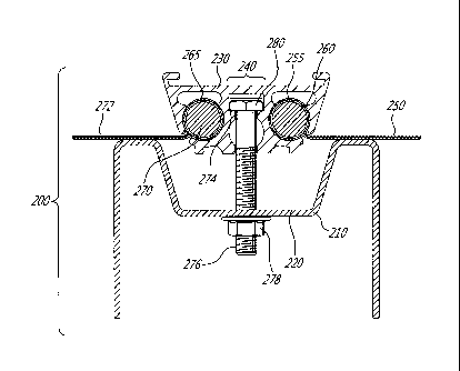
[0033] Figure 2 shows an exemplary cross-section from above of
the
membrane covered structure 100 showing a system for retaining membrane on a
structure 200. In Figure 2A, sheets of membrane 250 and 272 are under desired
tension for an assembled structure. In Figure 2B, the sheets of membrane 250
and 272
are not under desired tension for an assembled structure. The system for
retaining
membrane over the structure comprises a truss 210 of the structure 100. The
system
for retaining membrane over the structure further comprises a fastening
mechanism
240 comprising a channel 220 for receiving a connecting member 230. In the
example
of Figure 2, the channel 220 is provided with the truss 210. The fastening
mechanism
240 is for maintaining the connecting member 230 within the channel 220. In an
exemplary embodiment of the system for retaining membrane on a structure 200,
the
connecting member 230 comprises multiple sub-connecting members (not shown)
within the channel 220 of the truss 210. The first sheet of membrane 250 may
have a
first guiding strip 260 and a second guiding strip (shown in Figure 4). In the
example of
Figure 2, the first guiding strip 260 is inserted in a radial channel 255 of
the connecting
member 230. The fastening mechanism 240 allows adjusting depth at which the
connecting member 230 is maintained in the channel 220. Tension in the first
sheet
250 is thereby adjusted through the fastening mechanism 240. In the example
shown
in Figure 2B, the connecting member 230 is maintained at the bottom of the
channel
220. Skilled readers will understand that, in order to obtain the desired
tension in the
sheets 250 (and 272), the connecting member 230 may be maintained in the
channel
220 without being in direct contact with the channel 220 or any other portion
of the
truss 210.
[0034] Figure 2C shows another exemplary embodiment of the system
for
retaining membrane on the structure 200. In the example shown on Figure 2C,
the
channel 220 is formed by an additional member 282. This additional member may
be
maintained onto a truss 284 using the fastening mechanism 240 as shown or
other
means (e.g., soldered therewith or otherwise configured to snap and hold
thereon).
[0035] In the exemplary embodiment of the system for retaining
membrane on
the structure 200 of Figure 2, the first guiding strip 250 is located on a
lateral portion
260 of the first sheet 250. The second guiding strip (shown in Figure 4) is
located on an
opposite lateral portion of the first membrane sheet (shown in Figure 4).
. .
=
PCT/CA2012/000862
CA 02885236 2015-03-16
17 January 2014 17-01-2014
r ati It /11JIJIR,CILIIJI I
7
[0036] Sealing techniques could be used in order to prevent
seepage through
the fabric sheet 250 or between the fabric sheet(s) and connecting member(s).
A
lubricant may also be used to facilitate the insertion of guiding strips into
radial
channels and reduce wear over time and/or on sections of the membrane sheets
250
and 272 that are expected to be in contact with the channel 220. For example,
these
lubricants may be a tape, a liquid or a powder.
[0037] In one example of a system for retaining membrane on
a structure 200,
the first sheet 250, or any other sheet on the membrane covered building, is
made of
fabric. A person ordinarily skilled in the art will readily recognize that the
first sheet 250
or the other sheets of the membrane covered building may be made of another
flexible
material without affecting the invention.
[0038] In the exemplary embodiment of the system for
retaining membrane on
a structure 200 of Figure 2, the connecting member 220 comprises a second
radial
channel 265. A first guiding strip 270 of the second sheet of membrane 272 is
inserted
in the second radial channel 265.
[0039] In the exemplary embodiment of the system for
retaining membrane on
a structure 200 of Figure 2, the connecting member 230 comprises a bottom
channel
272. The fastening mechanism 240 comprises screws 276 and nuts 278. Heads of
the
screws 280 are adapted to be received in the bottom channel 274 of the
connecting
member 230. The screws 276 are bolted into the channel 220 trough the truss
210.
Persons skilled in the art will readily recognize that the screws may be
substituted by
bolts (not shown) or other mechanism for fastening the connecting member 230
to the
truss 210, such as a spring system, without affecting the invention. Another
example of
a mechanism for fastening the connecting member 230 to the truss 210 is a bolt
shaped as a T which locks into place after inserting into the truss 210 and
when rotated
90 degrees. Screws could also be first inserted into the truss and bolted into
the
connecting member (not shown).
[0040] In the exemplary embodiment of the system for
retaining membrane on
the structure 200 of Figure 2, tension can be adjusted by applying torque to
the bolted
screws 276 maintaining the connecting member 230 into the channel 220 of the
truss
210.
[0041] In the exemplary embodiment of the system of Figure
2, the first guiding
strip 260 and the second guiding strip 270 are both flexible and made of a
polymer.
Persons ordinarily skilled in the art will readily recognize that the guiding
strips 260 and
AMENDED SHEET
CA 02885236 2015-03-16
WO 2014/043779
PCT/CA2012/000862
8
270 could be composed of other flexible material aside from a polymer without
affecting
the invention. Guiding strips may further be replaced by other mechanisms for
joining a
membrane sheet to a connecting member, such as a snapping mechanism (not
shown), without affecting the invention.
[0042] The
connecting member 230 may be made of aluminum, an aluminum
alloy, a polymer, or a mixture of both aluminum and a polymer. Skilled readers
will also
recognize that the connecting member 230 could be composed of other material
without affecting the invention. The connecting member 230 is expected to be
extruded, but other methods of fabrication of the connecting member would not
affect
the teachings of the present invention.
[0043] The
truss 210 may be made of steel or galvanized steel or a mixture of
both steel and galvanized steel. Other material aside from steel or galvanized
steel,
such as wood or aluminum, could be used without affecting the invention.
[0044]
Figure 3 shows an exemplary embodiment 300 where a membrane
sheet 405 is under tension after installation. Tension applied is related to
both a first
depth at which a first connecting member 310 is maintained, after being
inserted, in a
first top channel 315 of a first truss 320 and a second depth at which a
second
connecting member 325 is maintained, after being inserted, in a second top
channel
330 of a second truss 335. .
[0045] Figure 4
shows an exemplary embodiment where a membrane sheet
405 is under tension after installation. The tension is related to a depth at
which a first
connecting member 410 is maintained, after being inserted, in a first top
channel 415 of
a first truss 420. A first guiding strip 425 is inserted in a first radial
channel 430 of the
first connecting member 410. A second guiding strip 435 is inserted into a
first radial
channel 440 of a second connecting member 445 connected to a second truss 450.
In
the exemplary embodiment 400, the second truss 450 does not have a channel for
maintaining the second connecting member 445.
[0046]
Figure 5 shows an exemplary embodiment 500 where a membrane
sheet 505 is under tension after installation. The tension applied is related
to both a
first depth at which a first connecting member 510 is maintained, after being
inserted,
in a first top channel 515 of a first truss 520 and a second depth at which a
second
connecting member 525 is maintained, after being inserted, in a second top
channel
530 of a second truss 535. In the exemplary embodiment 500, the first
connecting
CA 02885236 2015-03-16
WO 2014/043779
PCT/CA2012/000862
9
member 525 comprises two radial channels 540 and 545 and the second connecting
member comprises one radial channel 550.
[0047] As an additional option, the membrane sheets 305, 405 or
505 could
span over an additional truss (not shown) between the shown trusses even
though this
additional truss is not comprised in a system for controlling tension in the
spanning
sheet.
[0048] Figure 6 shows an exemplary method 600 for installation of
membrane
on a structure. The exemplary method 600 comprises inserting a first guiding
strip
located on a lateral portion of a first membrane sheet into a radial channel
of a first
connecting member 610. A first guiding strip located on a lateral portion of a
second
membrane sheet is then inserted into a second radial channel of the first
connecting
member 620. The first connecting member is inserted into a first top channel
of a first
truss of the structure for receiving the first connecting member 630. The
first
connecting member is fastened in the first top channel of the first truss.
Tension
applied in the first sheet is related to a first depth at which the first
connecting member
is maintained in the first top channel 640. Exemplary cross-sectional views
for
installation of membrane over the structure 600 are shown in Figures 3, 4 and
5.
[0049] The method 600 for installation of membrane over the
structure of
Figure 6 may further comprise inserting a second guiding strip located on an
opposite
portion of the first membrane sheet into a first radial channel of a second
connecting
member (not shown). The second connecting member may then be inserted into a
second top channel of a second truss of the structure for receiving the second
connecting member (not shown). The second connecting member may then be
fastened in the second top channel of the second truss. The tension applied in
the first
sheet is related to both the first depth at which the first connecting member
is
maintained in the first top channel and a second depth at which the second
connecting
member is maintained in the second top channel of the second truss (not
shown).
[0050] An exemplary embodiment of the method 600 for installation
of
membrane over the structure of Figure 6 further comprises fastening the first
connecting member to the first top channel of the first truss by bolting
screws (not
shown). Screw heads of the screws are received in a first bottom channel of
the first
connecting member (not shown). The screws are bolted into the first top
channel of the
first truss (not shown). A person ordinarily skilled in the art will readily
recognize that
CA 02885236 2015-03-16
WO 2014/043779
PCT/CA2012/000862
the screws may be substituted by bolts (not shown) or other mechanism for
fastening
the connecting member to the truss without affecting the invention.
[0051] An exemplary embodiment of the method for installation of
membrane
over the structure 600 of Figure 6 further comprises fastening the second
connecting
5 member to the second top channel of the second truss by bolting screws
(not shown).
Screw heads of the screws are received in a first bottom channel of the second
connecting member (not shown). The screws are bolted into the second top
channel of
the second truss (not shown).
[0052] Figure 7 shows an exemplary method 700 for replacing a
membrane
10 sheet on a membrane covered structure. The membrane sheet to be replaced
is under
a first tension and inserted into a first connecting member fastened in a
first top
channel of a first truss. The membrane sheet to be replaced is also inserted
into a
second connecting member, which may be fastened in a second top channel of a
second truss. The exemplary embodiment of the method for replacing the
membrane
sheet to be replaced on the membrane covered structure 700 of Figure 7
comprises
unfastening 710 the first connecting member from the first top channel of the
first truss.
The membrane sheet to be replaced has a first guiding strip, located on a
lateral
portion of the first sheet, the first guiding strip inserted into a first
radial channel of the
first connecting member. The first guiding strip of the sheet to be replaced
is removed
from the first radial channel of the first connecting member 720. A second
guiding strip,
located on an opposite lateral portion of the membrane sheet to be replaced,
is
removed from a first radial channel of the second connecting member 730.
[0053] In the exemplary embodiment of the method for replacing a
membrane
sheet to be replaced on the membrane covered structure 700 of Figure 7, the
unfastening may further comprise unbolting screws which are bolted into the
first truss.
Screw heads of the screws may be received in a first bottom channel of the
first
connecting member (not shown). A person ordinarily skilled in the art will
readily
recognize that the screws may be substituted by bolts (not shown) or other
mechanism
which are unfastened to loosen the connecting member form the truss without
affecting
the invention.
[0054] The exemplary embodiment of the method for replacing a
membrane
sheet on the membrane covered structure 700 of Figure 7 may further comprise
unfastening the second connecting member from the second top channel of the
second
truss (not shown). In the same exemplary embodiment of the method for
replacing a
_
PCT/CA2012/000862
CA 02885236 2015-03-16
17 January 2014 17-01-2014
raient Application
11
membrane sheet to be replaced on the membrane covered structure 700 of Figure
7,
the unfastening may further comprise unbolting screws which are bolted into
the
second truss (not shown). Screw heads of the screws may be received in a
second
bottom channel of the second connecting member (not shown). In an exemplary
embodiment of the method for replacing a membrane sheet to be replaced on the
membrane covered structure 700 of Figure 7, the screws may be substituted by
bolts
(not shown) or other mechanism which are unfastened to loosen the connecting
member form the truss without affecting the invention.
[0055] The exemplary embodiment of the method for replacing a
membrane
sheet on the membrane covered structure 700 of Figure 7 may further comprise
inserting a first guiding strip located on a lateral portion of a replacing
membrane sheet
into the first radial channel of the first connecting member (not shown). A
second
guiding strip located on an opposite lateral portion of the replacing membrane
sheet
may further be inserted into the first radial channel of the second connecting
member
(not shown). In order to put the replacing sheet under control tension, the
first
connecting member is then fastened in the first top channel of the first
truss. The
tension applied in the replacing sheet is related to a depth at which the
first connecting
member is maintained in the first truss (not shown). The method for replacing
a
membrane sheet on the membrane covered structure 700 of Figure 7 may further
comprise fastening the second connecting member in the second top channel of
the
second truss (not shown). The tension applied in the replacing sheet would
then be
determined by the depth at which the first connecting member is maintained in
the first
top channel of the first truss and a depth at which the second connecting
member is
maintained in the second top channel of the second truss (not shown).
[0056] Exemplary embodiments have been described to demonstrate the use,
principles, and function of the invention disclosed herein. These descriptions
and
illustrations are non-limiting exemplary embodiments and no limitation to the
scope of
the invention is thereby intended. Any alteration or modification to the
device or
alternative application of the invention principles are contemplated to
normally occur by
those with ordinary skill in the art to which the invention relates. Likewise,
the
description of the present invention has been presented for purposes of
illustration but
is not intended to be exhaustive or limited to the disclosed embodiments. Many
modifications and variations will be apparent to those of ordinary skill in
the art. The
embodiments were chosen to explain the principles of the invention and its
practical
- ¨
AMENDED SHEET
CA 02885236 2015-03-16
WO 2014/043779
PCT/CA2012/000862
12
applications and to enable others of ordinary skill in the art to understand
the invention
in order to implement various embodiments.