Note: Descriptions are shown in the official language in which they were submitted.
CA 02885326 2015-03-18
WO 2014/052868 PCT/US2013/062363
- 1 -
SURGICAL TRAINING MODEL FOR LAPAROSCOPIC PROCEDURES
FIELD
[0001] This application claims priority to and benefit of U.S.
Provisional Patent
Application Serial No. 61/707,658 entitled "Surgical training model for
laparoscopic
procedures" filed on September 28, 2012 which is incorporated herein by
reference in
its entirety.
FIELD OF THE INVENTION
[0002] This application is generally related to surgical training
tools, and in
particular, to simulated tissue structures and models for teaching and
practicing various
surgical techniques and procedures related but not limited to laparoscopic,
endoscopic
and minimally invasive surgery.
BACKGROUND OF THE INVENTION
[0003] Medical students as well as experienced doctors learning new
surgical
techniques must undergo extensive training before they are qualified to
perform surgery
on human patients. The training must teach proper techniques employing various
medical devices for cutting, penetrating, clamping, grasping, stapling,
cauterizing and
suturing a variety of tissue types. The range of possibilities that a trainee
encounters is
great. For example, different organs and patient anatomies and diseases are
presented. The thickness and consistency of the various tissue layers will
also vary
from one part of the body to the next and from one patient to another.
Different
procedures demand different skills. Furthermore, the trainee must practice
techniques
in various anatomical environs that are influenced by factors such as the size
and
condition of the patient, the adjacent anatomical landscape and the types of
targeted
tissues and whether they are readily accessible or relatively inaccessible.
[0004] Numerous teaching aids, trainers, simulators and model organs
are
available for one or more aspects of surgical training. However, there is a
need for
model organs or simulated tissue elements that are likely to be encountered
and that
CA 02885326 2015-03-18
WO 2014/052868
PCT/US2013/062363
- 2 -
can be used in practicing laparoscopic, minimally invasive surgical
procedures. In
laparoscopic surgery, a trocar or cannula is inserted to access a body cavity
and to
create a channel for the insertion of a camera such as a laparoscope. The
camera
provides a live video feed capturing images that are then displayed to the
surgeon on
one or more monitors. Another trocar/cannula is inserted to create a pathway
through
which surgical instruments are passed. The surgeon performs the procedure
manipulating instruments placed through the keyholes while observing the
target
anatomy on the video display. The targeted tissue location such as the abdomen
is
typically enlarged by delivering carbon dioxide gas to insufflate the body
cavity and
create a working space large enough to accommodate the scope and instruments
used
by the surgeon. The insufflation pressure in the tissue cavity is maintained
by using
specialized trocars. Laparoscopic surgery offers a number of advantages when
compared with an open procedure. These advantages include reduced pain,
reduced
blood and shorter recovery times.
[0005]
Laparoscopic or endoscopic minimally invasive surgery requires an
increased level of skill compared to open surgery because the target tissue is
not
directly observed by the clinician. The target tissue is observed on monitors
displaying
a portion of the surgical site that is accessed through a small opening.
Therefore,
clinicians need to practice visually determining tissue planes, three-
dimensional depth
perception on a two-dimensional viewing screen, hand-to-hand transfer of
instruments,
suturing, precision cutting and tissue and instrument manipulation. Typically,
models
simulating a particular anatomy or procedure are placed in a simulated pelvic
trainer
where the anatomical model is obscured from direct visualization by the
practitioner.
Ports in the trainer are employed for passing instruments to practice
techniques on the
anatomical model hidden from direct visualization. Simulated pelvic trainers
provide a
functional, inexpensive and practical means to train surgeons and residents
the basic
skills and typical techniques used in laparoscopic surgery such as grasping,
manipulating, cutting, tying knots, suturing, stapling, cauterizing as well as
how to
perform specific surgical procedures that utilized these basic skills.
Simulated pelvic
trainers are also effective sales tools for demonstrating medical devices
required to
perform these laparoscopic procedures.
CA 02885326 2015-03-18
WO 2014/052868 PCT/US2013/062363
- 3 -
[0006] Therefore, it is desirable to present a model suitable for
practicing
certain surgical techniques described above. In particular, there is a need
for a model
that isolates particular steps or techniques of a procedure such as tying
knots, grasping,
manipulating and moving tissue in a simulated laparoscopic environment. The
laparoscopic training model is removably placed inside a simulated
laparoscopic
environment such as a laparoscopic trainer in which it is at least partially
obscured from
direct visualization. A camera and monitor provide visualization of the target
model to
the practitioner. After a technique is practiced, it is furthermore desirable
that such a
model permits repeatable practice with ease, speed and cost savings. In view
of the
above, it is an object of this invention to provide a surgical training device
that provides
a platform for practicing surgical techniques that also enables repeatable
practice. It
has been demonstrated that the use of simulation trainers greatly enhances the
skill
levels of new laparoscopists and are a great tool to train future surgeons in
a non-
surgical setting. There is a need for such improved, realistic and effective
surgical
training models.
SUMMARY OF THE INVENTION
[0007] According to one aspect of the invention, a surgical training
device for
training and practicing laparoscopic procedures is provided. The device
includes a
laparoscopic trainer. The laparoscopic trainer includes a trainer base portion
and a
trainer top portion connected to and spaced apart from the trainer base
portion to define
a trainer internal cavity between the trainer top portion and the trainer base
portion. At
least one aperture or a penetrable tissue simulation region for accessing the
trainer
internal cavity is provided. A scope configured to capture live video of the
cavity is
included and a video monitor is connected to the scope and configured to
display live
video of the cavity. A practice model is removably disposed inside the trainer
internal
cavity such that the practice model is observable via the scope and video
monitor yet
obscured from direct visualization by at least the trainer top portion. The
practice model
includes a base having an upper surface substantially facing upwardly toward
the
trainer top cover when disposed inside the laparoscopic trainer. The base
includes
more than one practice station located on the upper surface of a base. Each
practice
CA 02885326 2015-03-18
WO 2014/052868 PCT/US2013/062363
- 4 -
station includes a cavity having an opening to the upper surface. The cavity
extends
from the upper surface into the base. A cover is connected to and movable with
respect
to the base in the location of the cavity. The cover is movable between a
first position
covering the opening to the cavity in the base and a second position
uncovering the
opening to the cavity in the base. A removable target object is disposed
inside the
cavity. The object is hidden from view beneath the cover when in the first
position and
the object is removable from the cavity when the cover is in the second
position.
[0008] According to another aspect of the invention, a surgical
training device
is provided. The device includes a base having a top surface and a bottom
surface. A
plurality of practice stations is formed in the base facing the top surface.
Each practice
station includes a cavity formed in the base having an opening at the upper
surface and
extending into the base. A cover is connected to the base in the location of
the cavity.
The cover is movable with respect to the base between a first position
covering the
opening to the cavity and a second position uncovering the opening to the
cavity. A
removable target object is disposed inside the cavity. The object is hidden
beneath the
cover when in the first position and removable from the cavity when in the
second
position.
[0009] According to another aspect of the invention, a method for
practicing
laparoscopic procedures is provided. The method includes the step of providing
a
laparoscopic trainer. The laparoscopic trainer includes a trainer base portion
and a
trainer top portion connected to and spaced apart from the trainer base
portion to define
a trainer internal cavity between the trainer top portion and the trainer base
portion. At
least one aperture or a penetrable tissue simulation region for accessing the
trainer
internal cavity is provided. A scope configured to capture live video of the
cavity is
included and a video monitor is connected to the scope and configured to
display live
video of the cavity. A practice model is removably disposed inside the trainer
internal
cavity such that the practice model is observable via the scope and video
monitor yet
obscured from direct visualization by at least the trainer top portion. The
practice model
includes a base having an upper surface substantially facing upwardly toward
the
trainer top cover when disposed inside the laparoscopic trainer. The base
includes
more than one practice station located on the upper surface of a base. Each
practice
CA 02885326 2015-03-18
WO 2014/052868 PCT/US2013/062363
- 5 -
station includes a cavity having an opening to the upper surface. The cavity
extends
from the upper surface into the base. A cover is connected to and movable with
respect
to the base in the location of the cavity. The cover is movable between a
first position
covering the opening to the cavity in the base and a second position
uncovering the
opening to the cavity in the base. A removable target object is disposed
inside the
cavity. The object is hidden from view beneath the cover when in the first
position and
the object is removable from the cavity when the cover is in the second
position. The
method includes inserting at least one laparoscopic grasper through the at
least one
aperture or penetrable tissue simulation region into the trainer cavity. The
cover of one
practice station is grasped by the grasper and the cover is moved from a first
position to
a second position. The removable target object is removed from the cavity
while the
cover is in a second position. A laparoscopic grasper is used to maintain the
cover in
the first position while another laparoscopic grasper is inserted through the
at least one
aperture or penetrable tissue simulation region into the trainer cavity and
into the cavity
of a practice station having a cover in the second position. A removable
target object
located in the cavity of the practice station in the second position is
grasped by the user
employing a laparoscopic grasper and removed from the cavity of the practice
station.
The method further includes providing another practice station having a
plurality of
spaced apart pegs connected to the upper surface of the base and extending
upwardly
from the upper surface. Each peg is associated with a particular geometric
shape or
color and the removable target object includes an opening configured to be
passed over
at least one peg. The removable target object is associated with one of the
geometric
shapes or colors of at least one peg. The method includes the step of
identifying the
geometric shape or color of the removable target object and using a
laparoscopic
grasper to move the target object from a cavity of a practice station and
passing the
target object over a peg having a corresponding geometric shape or color. The
method
includes the step of providing another practice station in the base configured
for
practicing the tying and untying of knots using laparoscopic graspers. The
practice
station includes a first string attached at a proximal end to the upper
surface of the base
and a second string attached at a proximal end to the upper surface of the
base
adjacent to the first string. Each of the first and second strings has a free
distal end. A
CA 02885326 2015-03-18
WO 2014/052868 PCT/US2013/062363
- 6 -
removable target object is passed over one of the strings. The method includes
the
step of untying the knot and removing the target object from the string and
placing the
target object over one of the pegs. The method includes the step of
identifying the
geometric shape or color associated with the target object and moving it from
the string
onto a peg having an associated geometric shape or color that corresponds to
the
associated geometric shape or color of the target object. The method includes
holding
a flexible cover while removing a target object. The method also includes the
step of
penetrating a cover with a surgical instrument to access the cavity of a base
station to
remove a target object located inside the cavity.
BRIEF DESCRIPTION OF THE DRAWINGS
[0010] FIG. 1 illustrates a top perspective view of a surgical
training device
according to the present invention.
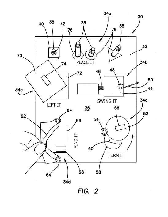
[0011] FIG. 2 illustrates a top view of a training model according to
the
present invention.
DETAILED DESCRIPTION OF THE INVENTION
[0012] A surgical training device 10 that is configured to mimic the
torso of a
patient such as the abdominal region is shown in FIG. 1. The surgical training
device
provides a body cavity 12 substantially obscured from the user and configured
for
receiving simulated or live tissue as well as model organs or a training model
of the like
described in this invention. The body cavity 12 is accessed via a tissue
simulation
region 14 that is penetrated by the user employing devices and instruments to
practice
surgical techniques on the tissue or organ model found located in the body
cavity 12.
Although the body cavity 12 is shown to be accessible through a tissue
simulation
region, a hand-assisted access device or single-site port device may be
alternatively
employed to access the body cavity 12. An exemplary surgical training device
is
described in U.S. Patent Application Serial No. 13/248,449 entitled "Portable
Laparosqopic Trainer" filed on September 29, 2011 and incorporated herein by
reference in its entirety. The surgical training device 10 is particularly
well suited for
practicing laparoscopic or other minimally invasive surgical procedures.
CA 02885326 2015-03-18
WO 2014/052868 PCT/US2013/062363
- 7 -
[0013] Still referencing FIG. 1, the surgical training device 10
includes a top
cover 16 connected to and spaced apart from a base 18 by at least one leg 20.
FIG. 1
shows a plurality of legs 20. The surgical training device 10 is configured to
mimic the
torso of a patient such as the abdominal region. The top cover 16 is
representative of
the anterior surface of the patient and the space between the top cover 16 and
the base
18 is representative of an interior of the patient or body cavity where organs
reside. The
surgical trainer 10 is a useful tool for teaching, practicing and
demonstrating various
surgical procedures and their related instruments in simulation of a patient
undergoing a
surgical procedure. Surgical instruments are inserted into the cavity 12
through the
tissue simulation region 14 as well as through pre-established apertures 22 in
the top
cover 16 or from the side between the top cover 16 and the base 18. Various
tools and
techniques may be used to penetrate the top cover 16 to perform mock
procedures on
simulated organs or training models placed between the top cover 16 and the
base 18.
The base 18 includes a model-receiving area 24 or tray for staging or holding
a training
model. The model-receiving area 24 of the base 18 includes frame-like elements
for
holding the model (not shown) in place to keep it from sliding around while
being
manipulated by surgical instruments. To help retain the model on the base 18,
a clip
attached to a retractable wire is provided at locations 26. The retractable
wire is
extended and then clipped to hold the model in position substantially beneath
the tissue
simulation region 14. Other means for retaining the model include a patch of
hook-and-
loop type fastening material (VELCRO ) affixed to the base 18 in the model
receiving
area 24 such that it is removably connectable to a complementary piece of hook-
and-
loop type fastening material (VELCRO ) affixed to the model.
[0014] A video display monitor 28 that is hinged to the top cover 16
is shown
in a closed orientation in FIG. 1. The video monitor 62 is connectable to a
variety of
visual systems for delivering an image to the monitor. For example, a scope
inserted
through one of the pre-established apertures 22 or a webcam located in the
cavity 12
and used to observe the simulated procedure can be connected to the video
monitor 28
and/or a mobile computing device to provide an image to the user. Also, audio
recording or delivery means may also be provided and integrated with the
trainer 10 to
provide audio and visual capabilities. Means for connecting a portable memory
storage
CA 02885326 2015-03-18
WO 2014/052868 PCT/US2013/062363
- 8 -
device such as a flash drive, smart phone, digital audio or video player, or
other digital
mobile device is also provided to record training procedures and/or play back
pre-
recorded videos on the monitor for demonstration purposes. Of course,
connection
means for providing an audio visual output to a larger screen other than the
monitor is
provided. In another variation, the top cover 10 does not include a video
display but
includes means for supporting a laptop computer, a mobile digital device or
tablet such
as an !PAD and connecting it by wire or wirelessly to the trainer.
[0015] When assembled, the top cover 16 is positioned directly above
the
base 18 with the legs 20 located substantially around the periphery and
interconnected
between the top cover 16 and base 18. The top cover 16 and base 18 are
substantially
the same shape and size and have substantially the same peripheral outline.
Although
the trainer 10 has no sidewalls, the legs 20 partially obscure the internal
cavity from
view from an otherwise open-sided trainer 10. In the variation shown in FIG.
1, the legs
20 include openings to allow ambient light to illuminate the internal cavity
as much as
possible and also to advantageously provide as much weight reduction as
possible for
convenient portability. The top cover 16 is removable from the legs 20 which
in turn are
removable or collapsible via hinges or the like with respect to the base 18.
Therefore,
the unassembled trainer 10 has a reduced height that makes for easier
portability. In
essence, the surgical trainer 10 provides a simulated body cavity 12 that is
obscured
from the user. The body cavity 12 is configured to receive at least one
surgical model
accessible via at least one tissue simulation region 14 and/or apertures 22 in
the top
cover 16 or the sides through which the user may access the models to practice
laparoscopic or endoscopic minimally invasive surgical techniques.
[0016] A model 30 for the practice of laparoscopic or open procedures
and
techniques according to the present invention is shown in FIG. 2. The model 30
is
configured to be placed inside the surgical training device 10 described above
or other
similar surgical trainer. The model 30 includes a base 32, and a plurality of
practice
stations 34 connected to the upper surface 36 of the base 32. Five practice
stations,
34a, 34b, 34c, 34d and 34e are shown in FIG. 2 and each is configured for
practicing an
individual surgical technique or exercise employing traditional laparoscopic
instruments.
CA 02885326 2015-03-18
WO 2014/052868 PCT/US2013/062363
- 9 -
[0017] The base 32 is a platform that serves as a bottom support for
the rest
of the model 30 and it is sized and configured such that the model does not
tip over.
The platform is made of any suitable material such as metal or plastic. The
base 32 is
of sufficient heft to maintain the stability of the model 30 in the upright
position while
being manipulated by a user. The model 30 is sized and configured to be placed
into
the body cavity 12 of the surgical trainer 10 in the location of the model
receiving area
24. The underside of the base 32 is provided with means to affix the model 30
inside
the surgical trainer 10 so that the model 30 does not move while being
manipulated.
Such means to affix the model 30 inside the trainer 10 include but are not
limited to
adhesive, suction cup, snap-fit, magnet, and a hook-and-loop type fastener
material
attached to the bottom surface of the base 32 and configured to connect to a
complementary hook-and-loop type fastener material or adhesive attached to the
base
18 of the surgical trainer 30.
[0018] The first practice station 34a includes one or more pegs or
posts 38
connected to the base 32 and extending upwardly from the upper surface 36 of
the
base 32. The pegs 38 are elongated and cylindrical in shape although the
invention is
not so limited and the pegs can be of any shape and size. The practice station
34a
includes an object 40 having an aperture 42 sized and configured to fit over
one of the
pegs 38. Placing the object 40 may require orienting the object such that the
aperture
42 of the object 40 aligns with the shape of peg 38. In one variation, pegs 38
having
different cross-sectional shapes are provided together with objects having
apertures 42
that correspond to the shape of the pegs 38. Complex polygonal pegs 38 and
objects
40 with corresponding polygonal-shaped apertures 42, for example, would
require the
user to manipulate the object 40 such that the aperture can be passed over one
of the
correspondingly-shaped pegs 38. In this exercise, the user employs a surgical
instrument such as a laparoscopic grasper inserted through an aperture 22,
simulated
tissue penetration region 14 or side of the trainer 10 to grab the object 40
lift it from one
peg 38 and place it on and over another peg 38 such that the aperture 42 of
the object
40 aligns with the peg 38 and fits onto the peg 38. In one variation, in the
plurality of
pegs 38, each peg 38 has a different height. The varying heights of the pegs
38 allow
the user to practice depth perception while placing the object 40. In another
training
CA 02885326 2015-03-18
WO 2014/052868 PCT/US2013/062363
- 10 -
procedure, the pegs 38 may have the same cross-sectional shape as shown in
FIG. 2
and the upper surface 36 of the base 32 is inscribed with various shapes 76.
Objects
40, 60, 68 retrieved from any of the other practice stations, such as stations
34b, 34c,
34d, may be placed over the peg 38 having the inscribed shape beneath the peg
38 that
corresponds to the shape of the retrieved object.
[0019] The second practice station 34b includes a cover 44. The cover
44 is
a rigid door 44 that is connected to the base 32 via a hinge 46 and the door
44 may
further include a knob 48 connected to the outer surface of the door 44. The
hinge 46
may be spring loaded such that the door 44 is biased in the closed position.
Underneath the door 44 is a cavity (not shown) that may include an object (not
shown)
that is hidden from view when the door 44 is closed. The cavity is formed in
the base
32 and may be any shape or size and depth. The cavity opens to the upper
surface 36
such that when the door 44 is moved, the cavity beneath the door 44 is
uncovered. In
this exercise, the user employs a surgical instrument such as a laparoscopic
grasper
inserted through an aperture 22, simulated tissue penetration region 14 or
side of the
trainer 10 to grab the knob 48 or door 44 to swing it open from a closed
position. If a
cavity is provided underneath the door 44, the user must maintain the door 44
in the
open position while another instrument in another hand is used to grab an
object
located inside the cavity and remove it. In one variation, a string 50 is
attached to the
knob 48 or door 44 to allow the user to grab the string 50 instead of the knob
48 or door
44 to swing and hold the door 44 open. The object may be placed over a peg 38
at the
first station 34a such that object is placed over the peg 38 having a shape 76
that
corresponds with the shape associated with the object.
[0020] The third practice station 34c includes a cover 52 connected to
the top
surface of the base 32 with a connector 54 and the cover 52 may further
include a knob
56 connected to the outer surface of the cover 52. The connector 54 is a
fastener that
permits the cover 44 to slide, swivel or pivot about the fastener along the
upper surface
36 of the base 32 to uncover a cavity 58 underneath the cover 52 with an
object 60
optionally located inside the cavity 58. The object 60 removed from the cavity
58 may
then be placed over a peg 38 that corresponds to the shape of the object 60.
The cavity
58 is formed in the base 32 and may be any shape or size and depth. A deeper
cavity
CA 02885326 2015-03-18
WO 2014/052868
PCT/US2013/062363
- 1 1 -
may increase the difficulty level of extracting the object 60. The cavity 58
may also be
sinuous or have a portion hidden from view by a wall such that the user would
have to
reach around the obstruction with an instrument to see if an object 60 is
hiding behind
the wall inside the cavity 58. The cavity 58 opens to the upper surface 36
such that
when the cover 52 is moved from a firS't position covering the cavity 58 to a
second
position uncovering the cavity 58, the opening to the cavity 58 as well as the
object 60
disposed inside the cavity 58 is revealed to the user. In this exercise, the
user uses a
surgical instrument such as a laparoscopic grasper inserted through an
aperture 22,
simulated tissue penetration region 14 or side of the trainer 10 to grab the
knob 56 or
cover 52 to turn it or slide it from a first closed position to a second open
position. If a
cavity 58 is provided underneath the cover 52, the user can then reach inside
the cavity
58 and grab the object 60 with the same grasper or another grasper held in an
opposite
hand of the user and remove the object 60 from the cavity 58 and place it to
the side or
remove it from the trainer 10. Alternatively, the object 60 may then be placed
over a
peg 38 at the first station 34a such that object 60 is placed over the peg 38
having a
shape 76 that corresponds with the shape associated with the object 60.
[0021] The
fourth practice station 34d includes a cover 62 connected to the
base 32. The cover 62 is made of flexible material such as a sheet of silicone
or fabric.
The cover 62 may also be made of material configured to simulate tissue such
as a
silicone or other polymeric sheet that may include a mesh or fabric
reinforcement. The
cover 62 is connected to the base 32 such that a flap 62 is formed. The flap
results
from at least one edge or portion of the cover 62 being sufficiently free so
as to be
capable of being lifted or separated from the upper surface 36. The cover 62
of station
34d is shown connected to the base 32 with two fasteners 64 leaving at least
one edge
of material that is graspable and capable of being moved or stretched away
from the
upper surface 36 to expose a cavity 66 located underneath the flap 62. The
fasteners
64 are screws or pins and any number may be employed to create a movable flap.
In
one variation, adhesive is used to connect at least a portion of the flap 62
to the upper
surface 36 of the base 32. At least a portion of the flap 62 is attached to
the base 32
such that at least a portion of the flap 62 can be moved upwardly or lifted to
reveal a
cavity 66 underneath the flap 62. The flap 62 can be elastic capable of being
stretched
CA 02885326 2015-03-18
WO 2014/052868
PCT/US2013/062363
- 12 -
as it is lifted or otherwise made to mimic real tissue. The cavity 66 is
formed in the base
32 and may be any shape or size and depth. An object 68 is disposed inside the
cavity
66. In this exercise, the user uses a surgical instrument such as a
laparoscopic grasper
inserted through an aperture 22, simulated tissue penetration region 14 or
side of the
trainer 10 to grab a free end of the flap 62 that is not affixed to the base
32, and then
pull the free end of the flap 62 to uncover the cavity 66 and the object 68
therein while
observing the model 30 on the video display 28 showing live images of the
procedure
within the body cavity 12. If a cavity 66 is provided underneath the flap 62,
the user
maintains the flap 62 in an open position uncovering the cavity 66 with a
grasper in one
hand and while using a second grasper in the opposite hand to retrieve the
object 68
from the cavity 66. FIG. 2 shows a user employing his fingers to pull and hold
the flap
62 open to uncover the object 68 inside the cavity 66 underneath the flap 62.
Of
course, the object 68 may then be placed over a peg 38 at the first station
34a such that
object 68 is placed over the peg 38 having a shape 76 that corresponds with
the shape
associated with the object 68. In one variation of practice station 34d, the
cover 62 is
not provided with a flap or free edge for lifting away from the upper surface;
but instead,
the flexible cover 62 completely covers and seals the cavity 66. In such a
variation, the
cover 62 is made of penetrable material such as a sheet of silicone that can
be pierced
or cut open to create a flap to simulate surgical incision made into tissue to
access the
cavity 66.
[0022] The
fifth practice station 34e includes a cover 70 in the form of a lid
that is located above a cavity 72. The lid 70 may include a knob 74. The cover
70 is
sized to completely cover and conceal the underlying cavity 72, can be any
shape and
may include protrusions on the undersurface of the lid 70 to help keep it in
place above
the cavity 72. In this exercise, the user employs a surgical instrument such
as a
laparoscopic grasper inserted through an aperture 22, simulated tissue
penetration
region 14 or side of the trainer 10 to grab the lid 70. The user may grab the
lid 70 or the
knob 74 connected to the lid 70. The user lifts the lid 70 from a first
position to a second
position uncovering the cavity 72 underneath and an object (not shown) located
inside
the cavity 72. The same grasper can be used to retrieve the object after
placing the lid
72 aside or alternatively, the user may use another grasper inserted through
an
CA 02885326 2015-03-18
WO 2014/052868 PCT/US2013/062363
- 13 -
aperture 22, simulated tissue penetration region 14 or side of the trainer 10
and held in
the opposite hand to retrieve and pull out the object found in the cavity 72.
Of course,
the object may then be placed over a peg 38 at the first station 34a such that
object is
placed over the peg 38 having a shape 76 that corresponds with the shape
associated
with the object.
[0023] In a sixth practice station that is not shown in FIG. 2, two
strings are
connected to the base 32. The strings are attached to the upper surface 36 of
the base
32 such that their connection points to the upper surface 36 are spaced apart.
Each
string has a free distal end and length of string approximately 1-3 inches
long measured
from its attachment point to its free distal end. The strings may be
interchangeable and
are in the range of 3-10 inches long and have various thicknesses for varying
the
difficulty level. In this exercise, the user employs a surgical instrument
such as a
laparoscopic grasper in one hand inserted through an aperture 22, simulated
tissue
penetration region 14 or side of the trainer 10 to grab the free length of the
first string
and a second surgical instrument such as a laparoscopic grasper in the other
hand
inserted through an aperture 22, simulated tissue penetration region 1401 side
of the
trainer 10 to grab the free length of the second string. Holding both lengths
of string,
the user manipulates the two strings in a manner of tying a knot such as a
suture knot.
In a variation of this exercise, an object 40 having an aperture is placed
over the string
and a knot is pre-tied over the object 40. The user then practices untying the
knot and
removing the object 40. The object 40 may have a shape that corresponds to the
shape
underlying one of the pegs 38. The user then moves the object 40 over the peg
38
having the same shape as the object 40. Each string may have a different color
in
which the tying or untying of a knot is easier than if the both strings were
the same
color.
[0024] In the above-described practice stations, a cavity may or may
not be
formed underneath each movable object. Furthermore, each cavity may be
different in
size and shape and depth from the upper surface 36 allowing the user to
practice depth
perception in retrieving the objects. Each cavity may contain one or more
objects with
one of the objects being the target or desirable object to be retrieved. There
may be
cutting exercises inside the cavity required to be performed to free the
object from the
CA 02885326 2015-03-18
WO 2014/052868 PCT/US2013/062363
- 14 -
cavity requiring the user to switch instruments for example and use a surgical
scalpel or
other cutting instrument. The objects also may be color coded such that the
user must
retrieve all objects of the same color. Also, in one variation, the target
object is not
located inside each cavity requiring the user to search for the target object
by lifting a
number of movable objects before finding the target object inside a cavity.
The user
may proceed to collect a more than one target object. Also, any number of
exercises
may be included in one base 32 and the exercises may be performed in a
particular
sequence that increases in difficulty. For example, lifting the lid 70 of the
fifth station
34e may be easier to perform than holding a trap door open while retrieving
the object
as required in the second station 34b. Also, various objects may be used and
the
objects can have any shape. For example, the objects can be spherical
cylindrical,
hoop-like, polymorphous and may include surface structures such as holes or
protrusions that would allow the user increased facility for manipulation.
[0025] With the model 30 disposed inside the cavity 12 of a
laparoscopic
trainer 10, the manipulations are performed with the distal ends of surgical
instruments
extending into the cavity 12 through ports 22, apertures 14 and/or sides of
the trainer
10. The proximal ends of the instruments are controlled by the hands of the
user
outside of the trainer 10. With the model 30 obscured from direct observation
of the
user, the user observes his/her manipulations of the model 30 on a video
screen
providing a live feed via a scope inserted into the cavity 12. This setup
increases the
difficulty in performing repeatable steps encountered in real surgery and
advances the
practitioner's laparoscopic surgical skills.
[0026] The model 30 is advantageously challenging and effective in
that the
user must use both hands equally and in tandem to complete several of the
exercises of
the practice stations. A stopwatch timer may be connected to the model so that
the
speed may be competitively recorded or evaluated for progress. Hence, the
model 30
is particularly useful for the practice of a variety of laparoscopic
techniques including
determining and visualizing tissue planes, the practice of depth perception,
hand-eye
coordination, hand-to-hand transfer of instruments, use of both hands,
switching
instruments, tying knots and tissue manipulation. This model allows the
clinician to
CA 02885326 2015-03-18
WO 2014/052868
PCT/US2013/062363
- 15 -
keep their skills sharp or to "warm-up" beforehand for successful outcomes in
real
surgery.
[0027] While certain embodiments have been particularly shown and
described with reference to exemplary embodiments thereof, it will be
understood by
those of ordinary skill in the art that various changes in form and details
may be made
therein without departing from the spirit and scope thereof as defined by the
following
claims.