Note: Descriptions are shown in the official language in which they were submitted.
CA 02885963 2015-03-23
WO 2014/067730 1
PCT/EP2013/070341
STABILIZER DEVICE FOR BOTTOM HOLE ASSEMBLY
The invention relates in general to a stabilizer for a bottom hole assembly.
In the field of
exploration and research into oil fields, strings of rotary drill pipe strings
constituted by pipes and
possibly other tubular elements are used which are connected end to end as
required by the drilling
conditions. A drill pipe string is a part of a drill stem which is tasked with
drilling a well bore and
which is composed of a lot of equipment for drilling. That pipe string is
connected to the bottom
hole assembly; together, they form a drill stem.
A drill stem is subjected to many loads, such as rotational and translational
movements
imposed by the surface equipment, vibrations created by the bottom hole tools
and contacts and
forces exerted between the well walls and the components of the stem; the well
may be more than
12 km long.
A bottom hole assembly may be composed, in succession from the drill bit which
is the
element which is closest to the well bottom, of the drill bit, any components
comprising the motors
for the drill bit, drill collars, equipment known as MWD and LWD, stabilizer
devices and heavy
weight drill pipe strings.
In a drill stem in particular, there is a need for stabilizing the bottom hole
assembly at
several positions between the drill bit and the heavy weight pipes. A
stabilizer acts to control the
deformation of the bottom hole assembly, in particular by providing a pre-set
point of inflexion for
the bottom hole pipes and the drill bit. It also assists in limiting vibration
in the pipe string and
controls the deformation as an element contributing to controlling the
deviation of the desired
trajectory.
The invention may also be applied to components for measuring or inspecting
the well
bottom, such as equipment known in the art by the terms MWB, LWD or even RSS.
Conventionally, in order to allow drilling, pressurized mud passes over the
drill bit disposed
at the end of a string of drill pipe strings at a regulated flow rate inside
the string of drill pipe strings
and is then pumped and lifted in the annular space defined between the stem
and the hole wall.
CA 02885963 2015-03-23
WO 2014/067730 2
PCT/EP2013/070341
Various stabilizer tools are known in the art, such as those produced by the
Applicant.
Documents US-4275935; US-6202769 and US-2010-0300760 in particular disclose
stabilizers
provided with external helical protrusions attached to a tubular body or
integral with said body.
The teaching of document US-2010-0300760 also discloses a set of tubular
bottom hole
drilling elements comprising a bore former disposed between the drill bit and
three upstream
stabilizers to improve the stability of the drill bit and the directional
control of the trajectory.
The aim of the invention is to improve the consolidation of the hole walls
while reducing the
coefficients of friction with those walls. In fact, formation of a hole
results in the formation of
debris corresponding to the material which is tom out to form the hole. This
debris is evacuated by
lifting it out with the drilling mud. It turns out to be very important that
lifting this debris does not
modify the dimensional characteristics of the hole being formed.
Further, given the short service life of the drill bit at the hole bottom,
when drilling a well
with a length of 4 to more than 10 km, it is necessary to have to lift the
drill stem assembly regularly
in order to be able to change or repair the drill bit and then to drop the
whole drill stem down again
in order to progress hole formation a little further. These operations of
lifting and dropping the
string solely for the purposes of maintenance and analysis (known as tripping
out and tripping in)
give rise to many frictional loads on the hole walls and also make a
substantial contribution to
deterioration of the quality of the hole in terms of homogeneity of the
diameter over its length,
cracking risks and risks of causing mud deceleration and turbulence zones in
enlarged diameter
zones and thus to the accumulation of rubble. More generally, these
operations, although necessary,
contribute to weakening of the hole and thus to increasing the risk of the
string getting blocked in
the hole.
This problem becomes more and more critical when approaching the bottom of the
well
where the diameter of the hole is very close to that of the bottom hole
assembly.
CA 02885963 2015-03-23
WO 2014/067730 3
PCT/EP2013/070341
The aim of the present invention is to propose a technical solution in
particular to limit
damage to the walls of the hole during tripping out and tripping in operations
while allowing proper
circulation of the mud.
The invention provides a stabilizer device for a drill stem, in particular for
a bottom hole
assembly, which is rotatable about a longitudinal axis, the device comprising
a tubular central body
and connection means at its axial ends for connecting to elements of the stem,
the device being
provided with a helical protrusion on the surface of the body intended to come
into contact with a
wall of the drilled hole, said helical protrusion turning in the clockwise
direction about the axis of
the central body viewed from an upstream axial end in the direction of a
downstream axial end,
characterized in that a crest of the helical protrusion comprises a leading
edge and a trailing edge
defined in the direction of rotation, the leading edge comprising a convex
portion such that a first
part of said convex portion has a radius of curvature of more than 3.5 mm over
an angular arc of at
least 20 .
The term "helical protrusion" means a shape with an envelope which is
generally helical.
As an example, this first part of the convex portion may have a radius of
curvature of more
than 5 mm over an angular arc of at least 30 .
The invention can be used to improve the geometric and mechanical coupling
between the
protrusions of the stabilizer and the walls of the well, in particular by
limiting dynamic impacts
which are the primary causes of lateral and torsional vibrations, and also by
improving the
homogeneity of the profile of the section of the hole being formed. The
invention can also be used
to obtain fluid bearing at the level of the stabilizer device.
The very particular shape of the leading edge provides for activated
circulation of the
drilling mud while providing a less aggressive profile as regards the walls of
the hole being formed.
Such a dimensional selection means that enlargement of the hole during
insertion or removal
operations for the drill string can be limited. This advantage is also
obtained during rotation during
drilling.
CA 02885963 2015-03-23
WO 2014/067730 4
PCT/EP2013/070341
Advantageously, the convex portion may also be complex and comprise at least
one second
convex portion adjacent to the first portion, said second portion having a
radius of curvature which
is smaller than that of the first portion, said second portion being located
ahead of the first portion in
the direction of rotation.
As an example, the convex portion may extend over an angular arc of less than
180 and
comprise a third portion, such that the second portion is disposed between the
first and the third
portion, and such that said third portion has a radius of curvature which is
larger than that of the first
portion. Such a configuration means that a larger cross section for movement
of the drilling mud
can be provided while improving contact, centring and guidance of the stem.
In particular, the parts of the convex portion may be linked tangentially.
Such a
configuration improves the dynamics of the rising drilling mud and the flow is
homogeneous along
the convex portion.
Advantageously, the crest of the helical protrusion can form an arc of a
circle linked
tangentially to the convex portion of the leading edge. In this manner, no
edge is formed that can
tear up the walls of the hole. Similarly, the crest of the helical protrusion
can form an arc of a circle
linked tangentially to the convex portion of the trailing edge.
In particular, the circular arc may have a diameter which is determined as a
function of the
theoretical diameter of the drilled hole at the well bottom or the external
diameter of the drill bit at
the well bottom; in particular, this diameter is determined by reducing the
theoretical diameter by a
value of at least 1/64 inch, i.e. 0.4 mm. This dimensional selection can be
used to consolidate the
walls of the hole by allowing a slight deflectional play at the stabilizer
device.
The trailing edge may also comprise a second convex portion such that the
crest of the
helical protrusion forms a circular arc linked tangentially to this second
convex portion.
Preferably, the device may comprise a material covering the crest and in part
at least one of
the leading edge and the trailing edge such that the hardness of this material
is much greater than
that of the helical protrusion. The presence of such a material means that
wear of the portions of the
CA 02885963 2015-03-23
WO 2014/067730 5
PCT/EP2013/070341
protrusion which are most exposed to contacts and to shocks against the walls
of the hole being
formed can be limited, and thus the number of maintenance operations on the
bottom hole elements
can be limited.
In a particular embodiment, a housing may be formed at the crest of the
helical protrusion in
order to retain a rotationally-free roller. The invention also concerns the
"roller reamer" category,
namely tools provided with blades or rollers that are generally used to
regularize and calibrate the
walls of a well.
In particular, the helical protrusion can form a radial foot with a minimum
width measured
perpendicular to a bisecting line such that this minimum width is smaller than
the maximum width
of said foot closer to the crest than the minimum width. Such a configuration
can be used to
increase the available section for circulation of the drilling mud while
maintaining the quality of
contact between the hole and said stabilizer.
Advantageously, the device may comprise a concave zone between a leading edge
and an
adjacent trailing edge. Preferably, each concave zone may comprise a first
concave portion linked
tangentially to the leading edge, said first concave portion having a radius
of curvature which is
smaller than that of a second concave portion linked tangentially to the
adjacent trailing edge. The
flow of drilling mud is thus principally caused to circulate more under the
leading edge than in the
proximity of the trailing edge. Acceleration of the trailing edge can thus be
improved in order to
allow the drilling debris to be dislodged rapidly.
As an example, the concave zone may define a profile tangential to the outer
perimeter of
the tubular body. Such a configuration means that the central body is not
weakened. Alternatively,
the concave zone may be located short of the outer perimeter of the tubular
body in order to increase
the cross section of passage for the flow of mud between the protrusions.
In particular, the helical protrusions may be spaced by a developed distance
such that two
adjacent protrusions may overlap in less than one turn or even less than one
half-turn, for example
from a quarter turn.
CA 02885963 2015-03-23
WO 2014/067730 6
PCT/EP2013/070341
Preferably, the helical protrusion turns through less than one turn about the
body, in
particular through a half turn. This configuration means that the presence of
said protrusion or
protrusions is limited axially such that the contact points of the protrusions
with the walls of the
hole being formed constitute the equivalents of points of inflexion for the
remainder of the drill
string. Advantageously, such a configuration can be used to improve the
dimensioning of the hole
and prevent it from being enlarged.
Preferably, the device may comprise protrusions over a total length defined
between its axial
ends of less than 120 inches.
Advantageously, the helical protrusion may be centred between the two axial
ends of the
device. Such a configuration means that the bending forces which may be
applied to the device can
be distributed in a balanced manner. Other non-centred configurations are also
acceptable.
In another embodiment, the downstream axial end may be directly part of or, in
a variation,
adjacent and screwed onto, the drill bit ("near-bit" stabilizer
configuration). In such a configuration,
the stabilizer device is directly integrated into the drill bit; in
particular, it is disposed downstream of
the rotary motors in the zone which is generally termed the bit gauge.
In a variation, the tubular body may constitute a fixed envelope screwed
around and onto a
tubular component having said connection means. In this case, the invention is
applicable to the
element known as the sleeve stabilizer.
In a further variation, the helical protrusion and the tubular body may be
produced in an
integral manner.
Preferably, the device is produced from steel, for example from one of the
steels
corresponding to the following standards: AISI 4135; AISI 4137; AISI 4140;
and/or AISI 4145.
The steel may in particular be amagnetic.
In a particular embodiment, the central body may have a bore such that the
minimum
thickness of the wall of this central body represents more than 25% of the
external diameter of this
body. Such a configuration increases the solidity of the whole of the device.
CA 02885963 2015-03-23
WO 2014/067730 7
PCT/EP2013/070341
The present invention will be better understood from the following detailed
description of
several embodiments which are given by way of non-limiting examples and
illustrated in the
accompanying drawings in which:
= Figure 1 illustrates an embodiment of a bottom hole assembly of a
conventional drill
stem in a hole being formed;
= Figure 2 diagrammatically illustrates the phenomenon of partial collapse
of walls of the
drilled hole;
= Figure 3 is a perspective view of a first embodiment of a stabilizer
device of the
invention;
= Figure 4 is a longitudinal view of a blank necessary for the production of a
device in
accordance with Figure 3;
= Figure 5 is a longitudinal view of Figure 3;
= Figure 6 is a cross sectional view in the sectional plane A-A indicated
in Figure 5;
= Figure 7 is an enlarged partial cross sectional view of Figure 6;
= Figure 8 is a cross sectional view in the sectional plane B-B indicated in
Figure 5;
= Figure 9 is a developed diagrammatic view of the helices formed by the
protrusions of a
device of the invention;
= Figure 10 is a distal view from a downstream male end of a device of the
invention;
= Figure 11 is a partial top profile view of a stabilizer device in
accordance with a
variation of the invention;
= Figure 12 is a cross sectional view in the sectional plane C-C indicated
in Figure 11;
= Figure 13 is a cross sectional view in the sectional plane D-D indicated
in Figure 11;
= Figure 14 is a variation of the embodiment of Figure 13;
= Figure 15 is a profile perspective view of a stabilizer device in
accordance with another
variation of the invention;
= Figure 16 is a cross sectional view in the sectional plane E-E of Figure
15.
CA 02885963 2015-03-23
WO 2014/067730 8
PCT/EP2013/070341
Figure 1 shows an embodiment of a bottom hole assembly 1. This assembly 1
comprises a
plurality of tubular components associated end to end forming a bottom hole
assembly upstream of
the drill bit 2 disposed at one axial end of said stem. For drilling reasons,
this assembly 1 is driven
in rotation in the clockwise direction, considered from an upstream end in the
direction of a
downstream end constituted by the drill bit. In drilling technology, the
direction of rotation is
always determined from the surface relative to the well bottom.
The drill bit comprises a motorized distal end 3 which is intended to excavate
the hole, and
an upstream portion 4 supporting the motorized end 3. The upstream portion 4
is occasionally
termed a bit gauge. In the example shown, the upstream portion 4 is smooth.
The upstream portion 4 is then connected by makeup to a first tubular
component 5 which is
then connected upstream, by makeup, to a first stabilizer device 6 of the
invention. This stabilizer
device 6 is itself made up upstream to a well bottom measuring device 7. This
well bottom
measuring device 7 may comprise several tubular sections made up end to end in
order to carry out
a plurality of measurements and checks at the well bottom. This measuring
device 7 may also
comprise rotary-steerable means (RSS) for the drill bit 2.
This measuring device 7 is connected upstream to a second stabilizer device 8
of the
invention, which may be structurally different from the first stabilizer
device 6. Preferably, the
second stabilizer device 8 has been connected to thick-walled tubular elements
termed a drill collar
both downstream and upstream.
The second stabilizer device 8 is connected upstream to a calibration tool 9
provided with
blades or rollers that are free to rotate at its walls and are intended to
come into contact with the hole
walls. In the example shown, the calibration tool has an adjustable diameter.
Alternatively, at the
position of this calibration tool 9, it is possible to provide a roller reamer
the external diameter of
which is not adjustable but which could form a third stabilizer device with
freely rotatable rollers, as
will be described in detail below.
CA 02885963 2015-03-23
WO 2014/067730 9
PCT/EP2013/070341
This calibration tool 9 is itself connected upstream to a fourth stabilizer
device 10 in
accordance with the invention, which may be different in shape, structure
and/or dimensions
compared with the preceding stabilizer devices disposed downstream. This
fourth stabilizer device
is connected to a group 11 of several tubular components in particular
comprising a sliding
5
component 12 that is capable of expanding axially on command in order, for
example, to unblock
the bottom hole assembly. This sliding component 12 is generally known as a
jar.
This group 11 is then made up upstream with one or more heavy pipes 13
generally known
as heavy weight drill pipes before being connected to a drill string
principally constituted by drill
pipe.
10
As can be seen from this overall description, a stabilizer device in
accordance with the
invention may be placed at several positions in a bottom hole assembly 1 and
have mutually
differing shapes, structures and/or dimensions.
These stabilizer devices have, at least locally along their longitudinal axis,
an external
diameter close to that of the hole being formed or the external diameter of
the drill bit. Their role is
to keep the pipe string and the bottom hole assembly stable in the hole while
the drill bit is subjected
to very powerful vibrations in contact with the rock to be excavated, while
keeping the pipe string
rotating in the hole. In addition, these stabilizer devices contribute to
improving directional control
of the drill bit in the formation to be excavated in order to reach
hydrocarbon-bearing rocks which
will then be worked.
Figure 2 illustrates a classic drilling problem. Because geological strata are
traversed which
have different hardnesses and even different structures, the hole being formed
may pass through
different strata. The quality of the walls of the hole and their continuity is
a parameter which is very
important to control during drilling in order to completely control the rising
mud flows and also to
prevent the drill string from being blocked in situ.
Figure 2 shows an example of the partial collapse of the walls of a hole being
formed in a
friable zone 14. The invention can be used to limit erosion and weakening of
the hole walls. These
CA 02885963 2015-03-23
WO 2014/067730 10
PCT/EP2013/070341
fallen rocks 15 of randomized sizes fall down to the bottom of the well and
risk damaging the drill
bit per se, even more so when it is not designed to crush this type of fallen
rocks into pieces with a
size similar to those produced during drilling. As can be seen in this Figure
2, there is a genuine
need for consolidation of the walls of the hole being formed without damaging
them and of limiting
the vibrations which can favour fallen rocks.
Figure 3 presents a first embodiment of a stabilizer device 20 of the
invention. The
stabilizer device 20 comprises a tubular central body 21 with a longitudinal
axis X and is provided
at these axial ends with threaded portions respectively 22 and 23 to enable it
to be connected to
other elements of the bottom hole assembly. In the example shown, the end 22
comprises a male
connector with a visible threading, while the other end 23 has a female
connector, the threading of
which, which is not shown, is located on the inner perimeter of this end.
The outer perimeter of the central body 21 is generally a regular circle in
section transverse
to the axis X. At the position where three radial helical protrusions 24, 25,
26 extend beyond the
outer perimeter of the central body 21, the device 20 locally has an envelope
surface the cross
section of which has a diameter which is greater than that of the central body
21. These radial
protrusions are generally termed blades.
The three protrusions turn about the axis X. They each turn through a half
turn about the
axis X in the example shown. The respective starting points of each of these
helical protrusions are
distributed regularly about the periphery of the central body 21.
Assuming that the male connector can constitute a downstream connector of this
device
relative to the drill string, it may be considered that the helical
protrusions turn in the clockwise
direction considered from an upstream end in the direction of a downstream
end. These protrusions
turn in the same direction as the direction of rotation W of the pipe string
and thus of the bottom
hole assembly in the hole.
A tubular blank E such as shown in Figure 4 is used as the starting point for
producing such
a stabilizer device 20. This tubular blank E is preferably produced as a
single piece in a single
CA 02885963 2015-03-23
WO 2014/067730 11
PCT/EP2013/070341
material which is then machined to size. In practice, this blank E already
comprises the central
body 21 at the ends of which the respective male 22 and female 23 connectors
will be machined.
The blank E comprises a median portion 27 substantially at equal distances
from its axial ends 22
and 23. The distance between the ends 22 and 23 is, for example, 120 inches or
less. The median
portion 27 forms a tubular portion with an external diameter which is greater
than that of the rest of
the central body.
In particular, the internal diameter of the bore of the blank E may be
constant over its entire
length. As an example, the thickness of the wall of such a stabilizer device
20 is selected such that
it represents more than 25% of the external diameter, namely the diameter OD1
and/or the diameter
OD2.
The variation in diameter between the diameter OD1 of the central body 21 and
the diameter
0D2 of the median portion 27 is approximately symmetrical in this example
either side of the
median portion 27. In a variation, not shown, the variations in upstream and
downstream diameters
may be asymmetrical.
In particular, this enlargement 32 comprises, in succession from the diameter
OD1:
= a flared concave portion 28 with a radius of curvature R1, for example of
the order of 85
mm, in the range 50 to 300 mm;
= followed by a flared planar portion 29 with an inclination, for example,
of the order of
45 relative to the axis X, over a distance of the order of 100 mm;
= followed by a convex first fillet portion 30 with a radius of curvature R2,
for example of
the order of 80 mm, in the range 50 to 300 mm;
= followed by a second convex fillet portion 31 with a radius of curvature
R3 which is
greater than the radius of curvature R2, for example of the order of 130 mm,
in the range
50 to 300 mm;
= this second convex fillet portion 31 connecting to the outer perimeter with
external
diameter 0D2.
CA 02885963 2015-03-23
WO 2014/067730 12
PCT/EP2013/070341
In the example shown, each portion of the enlargement 32 links tangentially to
the next.
Similarly, the central body 21 links tangentially to the concave flared
portion 28. In addition, the
convex fillet portion 31 is linked tangentially to the outer perimeter of the
median portion 27.
This progression of the enlargement 32 contributes to softening contact
between the
protrusions 24, 25 and 26 with the walls of a hole being drilled. This
prevents scraping or
penetration into the hole wall. This progression is retained in the ends which
begin and terminate
the various protrusions 24, 25 and 26. In fact, as can be seen in Figure 5,
the protrusions 24, 25 and
26 are formed in the thickness of these enlargements 32 and in the median
portion 27. Thus, as the
drill string is advanced and/or withdrawn, the protrusions of a stabilizer
device of the invention
come into progressive contact with the hole wall and no not excavate it any
more than has already
been done.
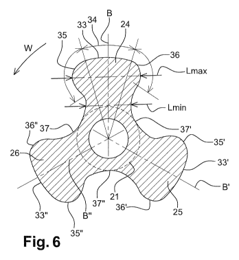
The cross sectional views of Figures 6 and 7 provide a better understanding of
the
dimensions of the protrusions machined in the blank E.
As can be seen in Figure 6, the protrusions 24, 25 and 26 are distributed
angularly at the
crests of an equilateral triangle; its bisecting lines B, B' and B" are shown.
The three protrusions
are superimposable in shape. Each protrusion 24, 25 and 26 respectively has a
crest 33, 33' and 33"
forming a non-machined portion of the enlargement 32 or of the median portion
27. Each crest 33,
33' and 33" covers an angular arc 34 of the order of 32 when it is formed in
the median portion 27,
preferably in the range 20 to 60 . This angular arc 34 is the same or smaller
when it is evaluated in
the enlargement 32. Each crest 33, 33' and 33" is preferably distributed
symmetrically either side
of the bisecting line with which it intersects, respectively B, B' and B".
Alternatively, the crests
could respectively be distributed in a non-symmetrical manner either side of
the bisecting lines.
In operation, as the drill string advances in the hole, the stabilizer device
20 is driven in
rotation in the clockwise direction W. Each protrusion 24, 25, 26 respectively
has a leading edge
35, 35' and 35" and a trailing edge 36, 36' and 36" relative to this clockwise
direction. The leading
CA 02885963 2015-03-23
WO 2014/067730 13
PCT/EP2013/070341
edge is the edge which will come into contact first with the wall of the hole,
and the trailing edge
will come into contact next.
The leading edges 35, 35' and 35" and the trailing edges 36, 36' and 36" each
comprise a
convex portion. In the example shown, the leading edges and the trailing edges
are solely
constituted by said convex portion. The leading edges form a complex convex
portion which is
generally not superimposable, nor symmetrical with the complex convex portion
constituted by the
trailing edges. Alternatively, the leading edges could be designed so as to be
symmetrical with the
trailing edges. In this example, the leading edges 35, 35' and 35" are
mutually superimposable.
Similarly, the trailing edges 36, 36' and 36" are mutually superimposable.
In particular, the leading edge 35 is linked to the trailing edge 36" via a
first concave zone
37. Similarly, the leading edge 35' is linked to the trailing edge 36 via a
second concave zone 37'.
And the leading edge 35" is linked to the trailing edge 36' via a third
concave zone 37". The
leading edge 35, together with a portion of the concave zone 37, the crest 33,
the trailing edge 36
and a portion of the concave zone 37' form a radial foot relative to the
central body 21. In
particular, the foot or base of the blade on the body has a minimum width Lmin
at a non-zero
distance from the crest, this minimum width Lmin being evaluated perpendicular
to the bisecting
line B. In particular, the foot comprises a maximum width Lmax at a position
located between the
crest and the minimum width Lmin. The position of the minimum width Lmin is
located at a
tangent to the outer perimeter of the central body 21 or slightly beyond it in
the direction of the crest
33.
In detail, Figure 7 shows an enlargement of the leading edge 35 of the first
concave zone 37
and of the trailing edge 36".
The leading edge is, for example, constituted by three successive convex
portions 38, 39 and
40. These portions 38, 39 and 40 are linked tangentially. The second portion
is disposed between
the first and the third portions. The first portion 38 is linked tangentially
to the crest 33 with a
radius of curvature 0D2.
CA 02885963 2015-03-23
WO 2014/067730 14
PCT/EP2013/070341
In the case in which the diameter 0D2 is 311.15 mm (12 1/4 inches), then, the
radius of
curvature of the first portion 38 is of the order of 39 mm and extends along
an angular arc of the
order of 30 .
The table below illustrates the possible dimensional choices as a function of
the diameter of
the drilled hole and thus as a function of the maximum diameter 0D2 observed
at the crests of the
stabilizer device 20.
Max diameter of the drilled Maximum diameter of Minimum radius of curvature
hole at the well bottom (D), crest (0D2), in inches of first portion 38,
in mm
in inches
6 D ¨ 1/64 3.5 mm (9/64 inch)
8'/2 D ¨ 1/64 4.3 mm (11/64 inch)
12 1/4 D ¨ 1/32 7.5 mm (19/64 inch)
17'/2 D ¨ 1/16 13.9 mm (35/64 inch)
26 D ¨ 1/16 13.9 mm (35/64 inch)
Adjacent to the first portion 38, the second portion 39 has a radius of
curvature which is
smaller than that of the first portion. It also covers an angular arc that is
smaller than the first
portion. In particular, for the described embodiment in which the diameter 0D2
is 12 1/4 inches, a
radius of curvature of 25 mm is used for this second portion and for an
angular arc of the order of
.
Adjacent to the second portion 39, the third portion 40 has a radius of
curvature which is
15 higher than that of the first portion and also higher than that of the
second portion. This third
portion 40 covers an angular arc which is greater than that of the second
portion and nevertheless
smaller than the first portion. In particular, for the described embodiment in
which the diameter
0D2 is 12 1/4 inches, a radius of curvature of 46 mm is used for this third
portion 40 and for an
angular arc of the order of 20 .
Advantageously, the set of the three portions 38, 39 and 40, namely the
complex convex
portion 35 of the leading edge 38, are circumscribed by a single convex
portion covering an angular
arc of more than 90 and less than 180 such that this circumscribed single
convex portion has a
CA 02885963 2015-03-23
WO 2014/067730 15
PCT/EP2013/070341
radius of curvature equal to the largest of the individual radii of curvature
of each of the portions
constituting it.
In the example of Figure 7, the trailing edge 36" is, for example, constituted
by two
successive convex portions 41 and 42 in order to form a complex convex
portion. These portions
41 and 42 are linked tangentially. The fourth portion 41 is linked
tangentially to the crest 33" with
radius of curvature 0D2.
In the case in which the diameter 0D2 is 12 1/4 inch, then, the radius of
curvature of the
fourth portion 41 is of the order of 25 mm and extends in an angular arc of
the order of 25 . This
fourth convex portion 41 is disposed between the crest 33" and the fifth
portion 42. The fifth
portion 42 has a radius of curvature which is greater than that of the fourth
portion 41. It also
covers an angular arc which is greater than or equal to that of the fourth
portion 41. In particular,
for the embodiment described in which the diameter 0D2 is 12 1/4 inch, a
radius of curvature of 36
mm is used for this fifth portion 42 and over an angular arc of the order of
50 .
Advantageously, the set of the two portions 41 and 42 form a complex convex
portion of the
trailing edge 36" circumscribed by a simple convex portion covering an angular
arc of more than
90 and less than 120 , such that this circumscribed simple convex portion has
a radius of curvature
equal to the largest of the individual radii of curvature of each of the
portions constituting it.
As can be seen in Figure 7, the leading edge 35 is linked to the adjacent
trailing edge 36" via
the concave zone 37. In practice, this concave zone 37 comprises a tangent
point 43 with an
imaginary circle with a diameter less than or equal to the value OD1, and
corresponding to the
external diameter of the central body 21.
Between the leading edge 35 and the tangent point 43, that portion of the
concave zone 37
belongs to the foot formed by the first protrusion 24. Between the trailing
edge 36" and the tangent
point 43, the other portion of the concave zone 37 belongs to the foot formed
by the third protrusion
26. This other portion comprises a second concave portion 45 adjacent to the
trailing edge 36".
CA 02885963 2015-03-23
WO 2014/067730 16
PCT/EP2013/070341
The radius of curvature of the first concave portion 44 is less than that of
the second
concave portion 45. In practice, in the example of Figure 7, the radius of
curvature of the first
concave portion 44 is of the order of 21 mm, while that of the second concave
portion 45 is of the
order of 68 mm. The angular arc covered by each of these concave portions 44
and 45 is in the
range 15 to 40 , for example of the order of 25 .
In the embodiment described, the concave zone 37 is in practice a complex
concave surface.
It is composed, in succession from the adjacent first concave portion 44, of a
third concave portion
46 extending with the same radius of curvature to a tangent point 43. The
third concave portion 46
is tangentially linked to a fourth concave portion 47 extending with the same
radius of curvature to
the second concave portion 45.
The radius of curvature of the third concave portion 46 is larger than the
radius of the three
other concave portions 44, 45 and 47. In practice, in the example of Figure 7,
the radius of
curvature of the third concave portion 46 is of the order of 100 mm while that
of the fourth concave
portion 47 is of the order of 50 mm. The angular arc covered by each of these
concave portions 44
and 45 is in the range 15 to 40 .
The angular arc covered by each of these concave portions 44, 45, 46 and 47 is
in the range
80 to 100 .
After having described the section of the device 20 in detail by means of
Figures 6 and 7 in
a zone in which the protrusions have their crest with the same radius of
curvature as a circle with
diameter 0D2, we shall now described the details of Figure 8, corresponding to
a section of the
protrusions observed in an upward incline constituted by one of the
enlargements 32.
The distinctions between the section of Figure 6 and that of Figure 8 will now
be
highlighted:
= in the enlargement zone, the radial foot formed by each protrusion does
not comprise a
maximum width Lmax at a position located between the crest and the minimum
width
CA 02885963 2015-03-23
WO 2014/067730 17
PCT/EP2013/070341
Lmin. In fact, the width of each foot decreases continuously from its zone of
attachment
to the central body 21 to its crest 33;
= the leading edges 35, 35' and 35" and the trailing edges 36, 36' and 36"
extend over an
angular arc which is much smaller than the respective angular arcs described
above for
Figures 6 and 7;
= the leading edges 35, 35' and 35" and the trailing edges 36, 36' and 36"
may be convex
surfaces with a continuous radius of curvature in the enlargements 32;
= the trailing edges 36, 36' and 36" have a radius of curvature which is
generally less than
or equal to that of the leading edges 35, 35' and 35";
= the concave zones 37 may be concave surfaces with a continuous radius of
curvature in
the enlargements 32.
The set of dimensions given above are measured after depositing a layer of a
highly friction-
resistant material. In fact, given the envisaged use of such stabilizers, it
is usual to cover at least the
crests and at least a part of the leading edges and trailing edges with a
material which is generally
termed a hardbanding material. This material may be deposited by welding, for
example by laser
welding, or by spraying or surface treatment processes.
In the embodiment shown diagrammatically in Figure 9, the blades of the
protrusions are
spaced by a developed distance d which is very substantially smaller than the
axial distance covered
by the blade in one turn. A geometrical pitch is the distance covered by the
blade in making one
turn. In practice, the blades of the protrusions 24, 25 and 26 make less than
one turn, and rather,
substantially half a turn.
In practice, the developed distance d is less than the axial distance actually
traversed by the
protrusion, Dp. As an example, the developed distance d is of the order of the
maximum width
Lmax of a protrusion.
In a variation, not shown, the blade may turn about the principal body with a
non-constant
angle, for example gradually increasing along the blade.
CA 02885963 2015-03-23
WO 2014/067730 18
PCT/EP2013/070341
Figure 10 shows that the maximum width, Lmax, of a protrusion increases
between its
beginning in the enlargement 32 to the median portion 27, this variation
possibly resulting from the
presence of a transition portion between the tubular central body 21 and the
median portion 27, in
which portion the protrusions 24, 25 and 26 begin and in which the leading
edges and trailing edges
may comprise other radii of curvature than those described above, in order to
prevent said edges
from excavating the hole walls being formed, in particular under the effect of
advance or
withdrawal of a drilling component in the well.
Figure 11 shows a variation of a stabilizer device in accordance with the
invention. In the
example of Figure 11, the stabilizing function of the device 120 is carried
directly in a downstream
portion termed the bit gauge at the drill bit, not shown. In this embodiment,
the device 120
embodying the invention is disposed at one end of the bottom hole assembly,
this latter comprising
a single connector 122 for connection with the upstream elements.
In a zone 150, defined axially upstream of the drill bit, close to the
connector 122, the outer
perimeter has protrusions with a profile corresponding to that observed in the
first embodiment of
the stabilizer 20. The distinction between the stabilizer 20 arises from the
fact that the zone 150 in
this example 5 comprises protrusions distributed evenly over the perimeter of
this zone.
Downstream of this zone 150 in the direction of the well bottom, the device
120 comprises a
zone 151 with a cross section which may have two alternatives, shown
respectively in Figures 13
and 14. In Figures 13 and 14, each of the protrusions of the zone 150
continues with the same pitch
as in the zone 151, but changes in cross section. In fact, in Figure 13, each
leading edge of the five
protrusions has an acute angle in order to excavate, in part, the walls of the
hole being formed.
When the protrusions are at an acute angle, their leading edges may include
inserts formed from
polycrystalline diamond (PCD).
In a variation, in Figure 14, only three protrusions out of the six have
leading edges with
such sharp angles. The protrusions with a profile of the type seen in zone 150
are alternated with
the protrusions with an sharp profile.
CA 02885963 2015-03-23
WO 2014/067730 19
PCT/EP2013/070341
In particular, as can be seen in Figure 11, in the zone 151, successively
along the axis X, the
leading edge may have profiles which are sharp to a greater or lesser extent.
In particular, it may
have a repeat pattern which alternates softened profiles and sharp profiles.
The device of the invention may also be integrated into a portion of a drill
bit known as the
bit gauge.
In yet another variation of the invention, shown in Figures 15 and 16, a
roller reamer 220 is
described which has profiles for its leading edges and trailing edges which
are identical to those
described in the embodiment shown in Figures 2 to 7. In contrast, in this
example, the protrusions
are such that the blade has a twist with a zero angle of inclination relative
to the longitudinal axis X.
The difference between this embodiment and those described above also derives
from the fact that
the respective crests 33, 33' and 33" are each provided with a housing 250
which opens radially
outwardly. This housing 250 holds a roller 251. In particular, the roller 251
is provided with pins to
improve calibration of the walls of the well. In general, these pins are
produced from tungsten
carbide.
Throughout the description, the expression "comprising a" should be construed
as being
synonymous with "comprising at least one", unless specifically stated
otherwise.