Note: Descriptions are shown in the official language in which they were submitted.
CA 02886023 2015-03-25
WO 2014/047689
PCT/AU2013/001109
1
TITLE
"A CATHODE AND METHOD OF MANUFACTURING"
FIELD OF THE INVENTION
This invention is concerned with an electrode for electrolytic
processes. The invention is concerned particularly, although not exclusively,
with a cathode for an electrolysis process.
BACKGROUND OF THE INVENTION
Cathodes for electrolytic processes consist of a conducting bar and a
plate of stainless steel or titanium placed in an electrolytic solution
hanging
from the conducting bar.
A problem with existing cathodes is that the conducting bar made of
copper (which is a highly conductive metal) is welded to the stainless steel
or
titanium plate. The problem is that such a weld is difficult to produce and
has
bad resistance to acid mist Which is produced, potentially resulting in the
\ weld being quickly corroded and the plate becoming detached.
A problem with replacing the copper with a different metal is that there
would be a significant voltage drop, this, multiplied by the number of
electrodes in use and the high currents increases the operating costs
substantially. One way around this is to coat a stainless steel conducting bar
in copper, however, the copper coating separates from the stainless steel
after a while due to the corrosion produced by the acid mist of the
electrolytic
operation, leading to a larger voltage drop.
Another prior art solution is to weld the stainless steel to the copper in
a three part process where the first zone is formed of a copper-nickel alloy,
CA 02886023 2015-03-25
WO 2014/047689
PCT/AU2013/001109
2
an intermediate zone of mostly a nickel alloy and a second zone of stainless
steel-nickel. This results in a satisfactory solution but requires a special
welding process using nickel electrodes.
Any discussion of documents, acts, materials, devices, articles or the
like which has been included in the present specification is solely for the
purpose of providing a context for the present invention. It is not to be
taken
as an admission that any or all of these matters form part of the prior art
base or were common general knowledge in the field relevant to the present
invention as it existed before the priority date of each claim of this
application.
OBJECT OF THE INVENTION
It is an object of the invention to overcome or at least alleviate one or
more of the above problems and/or provide the consumer with a useful or
commercial choice.
Other preferred objects of the present invention will become apparent
from the following description.
SUMMARY OF THE INVENTION
In one form, although it need not be the only or indeed the broadest
form, the invention resides in an electrode for electrolytic processes, the
electrode comprising:
a conducting bar; and
a plate attached to the conducting bar;
wherein the conducting bar has a conducting member attached
thereto to increase the conductivity of the conducting bar.
CA 02886023 2015-03-25
WO 2014/047689
PCT/AU2013/001109
3
Preferably, the electrode is a cathode. More preferably, the cathode
can be used for electrolytic processes of copper production.
Preferably, the electrolytic processes are electrolytic processes of
copper production. For example, copper electro refining or electro winning.
Preferably, the conducting bar is made of stainless steel. Alternatively,
the conducting bar may be made from another suitable metal or alloy, such
as titanium. It will be appreciated that the conducting bar may also be
referred to as a hanger bar. Preferably the conducting member is attached to
the conducting bar by welding. The conducting bar preferably has an inside
surface. Preferably the conducting bar is hollow. More preferably the
conducting bar has a tubular shape that is made by roll forming.
Roll forming is typically a continuous bending operation in which a
long strip of sheet metal is passed through sets of rolls mounted on
consecutive stands, each set performing only an incremental part of the
bend, until the desired cross-section profile is obtained. Design of the rolls
used in the roll forming operation typically starts with a flower formation,
which is the sequence of profile cross-sections, one profile for each stand of
rolls.
Preferably the conducting member is made of copper or a copper
alloy. Alternatively, the conducting member may be made from another
suitable metal or alloy having low resistivity. Typically the conducting
member is welded to an inside surface of the conducting bar. Preferably the
conducting member is welded to an inside surface of the conducting bar
before the conducting bar is formed. For example, the conducting member is
CA 02886023 2015-03-25
WO 2014/047689
PCT/AU2013/001109
4
welded to a sheet or plate which is then roll formed into a conducting bar.
Preferably the plate is made from stainless steel. Alternatively, the
plate may be made from another suitable metal or alloy, such as titanium.
Preferably the conducting bar is made from the same material as the
plate. More preferably the conducting bar and plate are made of stainless
steel. Typically the plate is welded to the conducting bar. Alternatively, the
plate may be integrally formed with the conducting bar.
In one embodiment, the conducting bar may have a first and second
portion substantially in axial alignment, a third portion axially offset from
the
first and second portion, a fourth portion disposed between the first and
third
portion and a fifth portion disposed between second and the third portion.
Typically the plate is attached to the third portion. Preferably the axis of
the
third portion is below the level of the axis of the first and second portion.
A
benefit of this is that more of the plate can be in contact with an
electrolyte
solution. Preferably the conducting bar is roll formed into such a shape.
In another form, the invention resides in a method of manufacturing
an electrode, the method including the steps of:
attaching a conducting member to an inside surface of a conducting
bar; and
attaching a plate to the conducting bar.
Preferably the step of attaching the conducting member to an inside
surface of the conducting bar involves welding the conducting member to the
conducting bar.
Preferably the step of attaching the plate to the conducting bar
CA 02886023 2015-03-25
WO 2014/047689
PCT/AU2013/001109
involves welding the plate to the conducting bar.
Preferably the method includes the step of forming the conducting bar
into a hollow shape and/or a tubular shape. Preferably, the step of forming
the conducting bar into a hollow shape and/or a tubular shape involves roll
5 forming the conducting bar.
Preferably the method includes the step of forming the conducting bar
such that a first and second portion are substantially in axial alignment, a
third portion is axially offset from the first and second portion, a fourth
portion
is disposed between the first and third portion and a fifth portion is
disposed
between second and the third portion. Preferably, the step of forming the
conducting bar into such a configuration involves roll forming the conducting
bar. More preferably the method includes the step of forming the conducting
bar such that a first and second portion are substantially in axial alignment,
a
third inclined portion and fourth inclined portion are disposed between the
first and second portions, wherein the axes of the third inclined portion and
fourth inclined portion are angled relative to the axes of the first and
second
portions. Preferably the third inclined portion and the fourth inclined
portion
form an obtuse angle. Alternatively the third inclined portion and the fourth
inclined portion form a right angle or an acute angle. Preferably the third
inclined portion is adjacent to the fourth inclined portion.
In a further form, the invention resides in an electrode for electrolytic
processes, the electrode comprising:
a conducting bar; and
a plate attached to the conducting bar;
CA 02886023 2015-03-25
WO 2014/047689
PCT/AU2013/001109
6
wherein at least part of the conducting bar dips below an upper edge
of the plate.
Preferably at least a top part of the conducting bar dips below an
upper edge of the plate. Preferably, the conducting bar has a first and
second portion substantially in axial alignment, a third inclined portion and
fourth inclined portion disposed between the first and second portions,
wherein the axes of the third inclined portion and fourth inclined portion are
angled relative to the axes of the first and second portions. Preferably the
third inclined portion and the fourth inclined portion form an obtuse angle.
Alternatively the third inclined portion and the fourth inclined portion form
a
right angle or an acute angle. Preferably the third inclined portion is
adjacent
to the fourth inclined portion. Preferably the third inclined portion and the
fourth inclined portion are inclined inwardly relative to an upper edge of the
plate.
Preferably the plate comprises at least one cut-out. Preferably the at
least one cut-out is located between a plane defined by the upper edge of
the plate and a plane defined by the lowest part of the conducting bar.
Preferably the conducting bar is a conducting bar as disclosed in this
specification. Alternatively, the conducting bar may be made of copper
and/or a copper alloy.
=
In another form, the invention resides in a hollow conducting bar for
an electrode .having:
a conducting member attached to an inside surface of the conducting
bar.
CA 02886023 2015-03-25
WO 2014/047689
PCT/AU2013/001109
7
Preferably, the Conducting bar is made of stainless steel. Alternatively,
the conducting bar may be made from another suitable metal or alloy, such
as titanium. Preferably the conducting member is attached to the conducting
bar by welding.
- Preferably the conducting member is made of copper or a copper
alloy. Alternatively, the conducting member may be made from another
suitable metal or alloy having low resistivity. Preferably the conducting
member is welded to an inside surface of the conducting bar before the
conducting bar is formed. For example, the conducting member is welded to
a sheet or plate which is then roll formed into a conducting bar.
Preferably the conducting bar has a first and second portion
substantially in axial alignment, a third portion axially offset from the
first and
second portion, a fourth portion disposed between the first and third portion
and a fifth portion disposed between second and the third portion.
More preferably, the conducting bar has a first and second portion
substantially in axial alignment, a third inclined portion and fourth inclined
portion disposed between the first and second portions, wherein the axes of
the third inclined portion and fourth inclined portion are angled relative to
the
axes of the first and second portions. Preferably the third inclined portion
and
the fourth inclined portion form an obtuse angle. Alternatively the third
inclined portion and the fourth inclined portion form a right angle or an
acute
angle. Preferably the third inclined portion is adjacent to the fourth
inclined
portion.
CA 02886023 2015-03-25
WO 2014/047689
PCT/AU2013/001109
8
BRIEF DESCRIPTION OF THE DRAWINGS
To assist in understanding the invention and to enable a person
skilled in the art to put the invention into practical effect, preferred
embodiments of the invention will be described by way of example only with
reference to the accompanying drawings, wherein:
FIG 1 shows a section of a prior art cathode;
FIG 2 shows perspective schematic view according to an embodiment
of the invention;
FIG 3 shows a schematic cross sectional view of a conducting bar and
a conducting member according to an embodiment of the invention;
FIG 4 shows a schematic cross sectional view of the conducting bar
and a conducting member of figure 3 welded together;
FIG 5 shows a schematic cross sectional view of the conducting bar of
figure 4 formed into a hollow shape;
FIG 6 shows a schematic cross sectional view of the conducting bar of
figure 5 welded;
FIG 7 shows a schematic cross sectional view of the conducting bar of
figure 6 and a plate;
FIG 8 shows a schematic cross sectional view of the conducting bar
and the plate of figure 7 welded together;
FIG 9 shows a schematic cross sectional view of a conducting bar
according to an embodiment of the invention;
FIG 10 shows a schematic view of an electrode according to an
embodiment of the invention;
CA 02886023 2015-03-25
WO 2014/047689
PCT/AU2013/001109
9
FIG 11 shows a schematic view of an electrode according to an
embodiment of the invention;
Fig 12 shows a schematic view of an electrode according to an
embodiment of the invention.
DETAILED DESCRIPTION OF THE DRAWINGS
Figure 1 shows a prior art cathode 100 having a copper conducting
bar 101 and a stainless steel plate 103. The stainless steel plate 103 is
welded to the conducting bar 101 by welds 105. A problem with the stainless
steel/copper welds 105 is that they are susceptible to corrosion and do not
provide welds of high structural strength.
With reference to figure 2, there is shown an electrode in the form of a
cathode 10. The cathode 10 comprises a conducting bar 20 attached to a
plate 30 by welds 32. A conducting member 26 is attached to the conducting
bar 20 by welds 28.
The conducting bar 20 and the plate 30 are made of stainless steel
and as such the welds 32 are stainless steel welds of high structural strength
having resistance to corrosion. The conducting bar 20 is hollow, with an
inside surface 22. The conducting bar 20 is welded by a weld 24 to provide a
tube shaped conducting bar 20.
The conducting member 26 is made of copper and the welds 28 are
not required to be as strong as the welds 32, as there is minimal structural
load placed on welds 28.
The welds 28 are primarily for conductive purposes such that the
conductivity of the stainless steel conducting bar 20 is increased by the
CA 02886023 2015-03-25
WO 2014/047689
PCT/AU2013/001109
copper conducting member 26. A benefit of having the conductive member
26 welded to an inside surface 22 of the conducting bar 20 is that the
conductive member 26 and the welds 28 are less susceptible to corrosion. A
benefit of welding the conductive member 26 to the conductive bar 20 is that
5 the
conductive member 26 is not required to provide structural strength to the
conductive bar 20, as such, less copper material can be used, resulting in
= reduced costs.
With reference to figures 3, 4, 5, 6,7 and 8, there is shown a cathode
10 during various stages of production. In figure 3, the conducting member
10 26 is placed
on the inside surface 22 (i.e. this will become the inside surface)
of conducting bar 20 (i.e. this plate or sheet material will become the
conducting bar). In figure 4, the conduating member 26 is attached to the
conducting bar 20 by welds 28. In figure 5, the conducting bar 20 is roll
formed to provide a hollow shape. In figure 6, the conducting bar 20 is
sealed along its length by weld 24. In figure 7, the plate 30 is positioned
adjacent to the conducting bar 20. In figure 8, the plate 30 is attached to
the
conducting bar by welds 32.
With reference to figure 9, there is shown a cross sectional view of a
conducting bar 20 according to an embodiment of the present invention. The
conducting bar 20 is made of stainless steel and has a conducting member
26 made of copper attached to an inside surface 22 of the conducting bar 20
by welds 28. As can be seen from figure 9, the conducting member 26 has a
'U' shape cross section. A benefit of this is that the conducting member 26
can be made by bending or roll forming a sheet or plate material.
CA 02886023 2015-03-25
WO 2014/047689
PCT/AU2013/001109
11
With reference to figure 10, there is shown a cathode 10 according to
the present invention with a "straight" shaped conducting bar 20 and a plate
30 which is placed in electrolyte solution 50.
With reference to figure 11, there is shown a cathode 10 according to
the present invention with conducting bar 20 having a first portion 70 and a
second portion 72 substantially in axial alignment, a third portion 74 is
axially
offset from the first portion 70 and second portion 72, a fourth portion 76 is
, disposed between the first portion 70 and third portion 74 and a fifth
portion
78 is disposed between second portion 72 and the third portion 74. A plate
301s attached to the third portion 74 of the conducting bar 20. The plate 30
is
placed in electrolyte solution 50.
As can be seen by comparing figures 10 and 11, the cathode 10 in
figure 11 has more of the plate 30 in the electrolytic solution, this results
in a
lower voltage drop between the conducting bar 20 and the part of the plate
30 which is in the electrolytic solution 50.
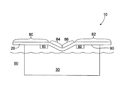
With reference to figure 12, there is shown a cathode 10 according to
the present invention with a conducting bar 20 having a first portion 80 and
second portion 82 substantially in axial alignment, a third inclined portion
84
and a fourth inclined portion 86 are disposed between the first portion 80 and
the second portion 82. The third inclined portion 84 and the fourth inclined
portion 86 are angled relative to the first portion 80 and the second portion
82. The plate 30 is attached to the conducting bar 20 and is placed in
electrolyte solution 50. As can be seen from figure 12, part of the third
inclined portion 84 and the fourth inclined portion 86 of conducting bar 20
dip
=
CA 02886023 2015-03-25
WO 2014/047689
PCT/AU2013/001109
12
below an upper edge 90 of the plate 30. Cut-outs 60 are located adjacent to
the conducting bar 20 and an upper edge 90 of the plate 30.
Throughout the specification the aim has been to describe the
invention without limiting the invention to any one embodiment or specific
collection of features. Persons skilled in the relevant art may realize
variations from the specific embodiments that will nonetheless fall within the
scope of the invention. For example, individual features from one
embodiment may be combined with another embodiment.
It will be appreciated that various other changes and modifications
may be made to the embodiment described without departing from the spirit
and scope of the invention.
Throughout this specification the word "comprise", or variations such
as "comprises" or "comprising", will be understood to imply the inclusion of a
stated element, integer or step, or group of elements, integers or steps, but
not the exclusion of any other element, integer or step, or group of elements,
integers or steps.