Note: Descriptions are shown in the official language in which they were submitted.
CA 02886088 2015-03-25
WO 2014/055693 PCT/US2013/063131
METHOD AND APPARATUS FOR HANDLING A TUBULAR
BACKGROUND OF THE INVENTION
Field of the Invention
[0001] Embodiments of the present invention generally relate to methods
and
apparatus for running a tubular such as a screen.
Description of the Related Art
[0002] Downhole screens are frequently used in the oil and gas industry
to filter
out sand or other particulates. Because of the porous nature of the screens,
it is
sometimes difficult to handle the screen without damaging it.
[0003] There is a need, therefore, for apparatus and methods for handling a
screen.
SUMMARY OF THE INVENTION
[0004] In one embodiment, a method of running tubulars includes
attaching a load
collar to a first tubular; landing the load collar on a load support member;
connecting a
second tubular to the first tubular; removing the load collar from the first
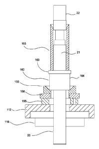
tubular; and
lowering the first tubular and the second tubular.
[0005] In another embodiment, a method of running tubulars includes
attaching a
load collar to a first tubular; landing the load collar on a load support
member;
positioning a stabbing guide on the load collar; and connecting a second
tubular to
the first tubular. In another embodiment, at least one of the first tubular
and the
second tubular comprises a screen.
BRIEF DESCRIPTION OF THE DRAWINGS
[0006] The patent or application file contains at least one drawing
executed in
color. Copies of this patent or patent application publication with color
drawing(s) will
be provided by the Office upon request and payment of the necessary fee.
[0007] So that the manner in which the above recited features of the
present
invention can be understood in detail, a more particular description of the
invention,
briefly summarized above, may be had by reference to embodiments, some of
which
are illustrated in the appended drawings. It is to be noted, however, that the
1
CA 02886088 2015-03-25
WO 2014/055693 PCT/US2013/063131
appended drawings illustrate only typical embodiments of this invention and
are
therefore not to be considered limiting of its scope, for the invention may
admit to
other equally effective embodiments.
[0oos] Figure 1 illustrates a hoisting and compensation configuration.
[0009] Figure 2 shows a partial view of an exemplary load collar coupled to
a
tubular.
[0olo] Figure 3 illustrates an exemplary tubular handling system.
[0oll] Figures 4-6 show an exemplary sequence of running a screen of
Figure 3.
[0012] Figures 7A-7C illustrate an exemplary load collar.
[0013] Figures 8A-8C illustrate another exemplary embodiment of a load
collar.
[0014] Figure 9 illustrates another exemplary embodiment of a load
collar.
[0015] Figures 10-17 illustrate an exemplary embodiment of a tubular
running
procedure using the load collar.
[0016] Figure 18 shows another embodiment of a sliding collar table.
[0017] Figure 19 illustrates another exemplary tubular handling system.
[0018] Figures 20-22 show an exemplary sequence of running a screen of
Figure
19.
[0019] Figure 23 illustrates an exemplary wash pipe installation system.
DETAILED DESCRIPTION
[0020] The present invention relates to apparatus and methods for handling
a
tubular. In one embodiment, a load collar is installed on a first tubular,
which is
lowered onto a load support member. A second tubular is then connected to the
upper end of the first tubular. The second tubular may be equipped with
another load
collar. Prior to connecting the second tubular, an optional stabbing guide may
be
disposed on the load collar to facilitate alignment and connection to the
first tubular.
After connection, the load collar on the first tubular is removed and the load
support
member may be opened to allow the first tubular to pass the rotary table.
Thereafter,
2
CA 02886088 2015-03-25
WO 2014/055693 PCT/US2013/063131
the load support member is closed and ready to engage the load collar on the
second
tubular.
[0021] Figure 1 shows an exemplary embodiment of a tubular handling
system 10
for handling a tubular. In one embodiment, the tubular may be a screen, or
other
types of tubulars such as drill pipe and casing. The tubular handling system
10
includes a traveling block 8 and elevator bails 25. The bails 25 suspend an
elevator
32 such as an automatic side door elevator ("ASD"). A hook 30 couples a
compensator 12 such as a single joint compensator to the traveling block 8. A
cable
plate 18 coupled to the lower end of the compensator 12 supports lifting
cables 34
having an elevator 37 attached to the cables' lower end. An exemplary elevator
37 is
a stabberless single joint elevator. Guide blocks 27 on the ASD 32 include
guide
rollers to facilitate movement of the lifting cables 34 relative to the ASD
32. A swivel
35 may be provided below the compensator 12 to allow rotation of the tubular
such as
a screen. An optional safety cable is provided with the compensator 12. The
tubular
handling system 10 may include a control panel 19 for the ASD 32 and the
compensator 12. The control lines 14 may be coupled to the control panel 19,
which
may include a remote control 29 for the operator.
[0022] Figure 2 is a perspective, partial view of an exemplary
embodiment of a
tubular such as a screen 20 having a small gripping area 23 for receiving a
handling
device such as a load collar 160. In one embodiment, the small gripping area
23 is a
recess formed around the exterior of the screen 20. The screen 20 may be
picked up
by the single joint elevator 37 at the V-door from a pipe delivery system. The
traveling block 8 may be lifted to hoist the screen 20 vertically and position
the screen
in the derrick for make-up. Although a screen 20 is described, it is
contemplated that
other types of tubular such as drill pipe and casing may be provided with the
gripping
area 23.
[0023] Figure 3 illustrates a screen 20 or a string of screens supported
by a collar
support 150. The screen 20 is shown having a first screen 21 connected to a
second
screen 22. The collar support 150 is disposed on a sliding collar table 112,
which, in
turn, is shown on top of the rig floor 116. In another embodiment, the collar
support
150 may be disposed on a sliding collar table 112. An optional shock absorber
155
may be provided below the collar support 150 to absorb load transfer shocks,
such as
during landing of the screen 20 on the collar support 150. An optional load
transfer
3
CA 02886088 2015-03-25
WO 2014/055693 PCT/US2013/063131
member such as a plate 158 may be used to transfer load to the shock absorber
155
and/or to spread the load over a larger surface area. In one embodiment, the
sliding
collar table 112 includes guides to allow for misalignment inside the master
bushing.
In one embodiment, the collar support 150 has an annular shape and includes
two
halves that can separate from each other. For example, the two halves can be
brought together to support the screen 20 and moved apart to allow the screen
20 to
pass through. In one embodiment, the two halves of the collar support 150 are
coupled together using a connection member such as a hinge.
In another
embodiment, the two halves are not physically coupled to each other. As shown,
the
collar support 150 includes an optional profile such as a recess for receiving
a load
collar 160, which is attached to the screen 20. In one embodiment, the recess
is
sized to centralize the load collar 160 in the collar support 150. Inclines
may be
provided to guide the load collar 160 onto the recess.
[0024]
Figures 2, 3, and 7B are different views of the load collar 160 coupled to
the
screen 20. Figure 3 is a perspective view of the load collar 160 and Figure 7B
is a
cross-sectional view of the load collar 160. The load collar 160 facilitates
handling of
the screen 20. The load collar 160 may include a tubular body 164 and an upper
surface having an opening 166 sized to engage the gripping area 23 of the
screen 20.
The opening 166 is smaller than the inner diameter of the load collar 160. The
load
collar 160 also includes a flange 163 on its outer surface. The flange 163 has
an
outer diameter that is larger than the outer diameter of the tubular body 164
of the
load collar 160. Figures 7A and 7B illustrate an exemplary the load collar 160
having
at least two portions that are coupled to each other using one or more hinges
to allow
opening and closing of the load collar 160. Figure 70 is a bottom view of the
load
collar 160 of Figure 7A. The load collar 160 may include one or more cut outs
167 in
the body 164 to reduce the weight of the load collar 160.
[0025]
Figures 8A-8C show different views of yet another embodiment of a load
collar 168. Figure 8A is a perspective view of the load collar 168. Figure 8B
is a
cross-sectional view of the load collar 168 coupled to a screen 20. Figure 8C
is a
bottom view of the load collar 168. In this embodiment, the load collar 168 is
provided
with ribs 169 that extend along the interior of the load collar 168 to provide
additional
structural support. In this respect, a load collar 168 may be provided with
ribs 169 to
support a higher string weight.
4
CA 02886088 2015-03-25
WO 2014/055693 PCT/US2013/063131
[0026] Figure 9 illustrates a partial view of another embodiment of a
load collar
170. In this embodiment, the load collar 170 includes one or more handles 171
to
facilitate handling of the load collar 170. The handles may be attached to the
cut-out
177 of the load collar 170. In one embodiment, when not in use, the handle 171
may
be retracted into the cut-out 177 such that the handle 171 does not protrude
out of the
body of the load collar 168. In Figure 9, one handle 171 is shown retracted
into a cut-
out 177, and one handle 171 is shown extended out of another cut-out 177. In
one
embodiment, the handles 171 may be coupled to a spring activated pin 176 which
is
configured to lock the position of the handles 171. For example, the spring
activated
pin 176 may bias the handle 171 in or out of a recess 178 in order to lock the
position
of the handle 171.
[0027] Referring back to Figure 3, the upper surface of the load collar
160 may
support a stabbing guide 165, which may be used to facilitate alignment of the
next
screen 22 or tubular to be connected to the first screen 21. In one
embodiment, the
stabbing guide 165 is tubular shaped and may include two portions that are
coupled
each other. The inner diameter of the stabbing guide 165 is sufficiently sized
to
accommodate the first screen 21 and to rest on the load collar 160. The upper
end of
the stabbing guide 165 may be funnel shaped to facilitate alignment of the
next
screen 22 to the first screen 21. In another embodiment, the stabbing guide
165 may
be positioned on the box of the first screen 21 and used to guide the second
screen
22 into alignment with the first screen 21.
[0028] In operation, the load collar 160 and the collar support 150 may
be used to
connect one or more screens to each other. As shown in Figure 3, the collar
support
150 is configured to support a first screen 21 via the load collar 160. The
load collar
160 may be pre-installed prior to being lifted by the traveling block 8. In
another
embodiment, the load collar 160 may be installed on the first screen 21 just
before the
first screen 21 lands on the upper end of the collar support 150. As shown,
the collar
support 150 is supported on a shock absorber 155 via the plate 158 to absorb
load
transfer shocks. Before the second screen 22 is added, the stabbing guide 165
is
positioned around the first screen 21 and on the load collar 160. Thereafter,
the
second screen 22 is lowered and stabbed into the first screen 21. After
removing the
stabbing guide 165, the two screens 21, 22 are threadedly connected to each
other
using, for example, a tong. Thereafter, the single joint elevator 37 is
lowered relative
5
CA 02886088 2015-03-25
WO 2014/055693 PCT/US2013/063131
to the second screen 22 to remove the load of the second screen 22 from the
single
joint elevator 37.
[0029] Referring now to Figure 4, after making up the connection, the
load collar
160 is removed from the first screen 21. The ASD 32 is used to grip the load
collar
162 of the second screen 22. Then, the sliding collar table 112 is opened, and
the
first screen 21 and the second screen 22 are lowered through the collar
support 150
and the sliding collar table 112. The ASD 32 supports the entire weight of the
screens 21, 22 as the screens 21, 22 are lowered. In Figure 5, the two halves
of the
collar support 150 are closed around the second screen 22. As shown, the ASD
32 is
equipped with an optional bushing 139 configured to engage the flange 163 of
the
load collar 162 of the second screen 22. In one embodiment, the bushing 139 is
configured to support an outer portion (e.g., the flange 163) of the lower
surface of the
load collar 162. In another embodiment, the ASD 32 may be configured to engage
the flange 163 of the load collar 162. After the load collar 162 lands on the
collar
support 150, the weight of the screens 21, 22 is transferred to the collar
support 150
as shown in Figure 6. Thereafter, the ASD 32 is lowered relative to the load
collar
162, and then opened and moved away from the load collar 162. This process may
be repeated to add one or more screens or tubulars. In this manner, one or
more
screens having a small gripping area may be connected to each other.
[0030] Figures 10-17 illustrate an exemplary embodiment of a tubular
running
procedure using the load collar. In this embodiment, the tubular is a screen.
Referring to Figure 10, the sliding collar table 112 is shown in the closed
position and
includes a load transfer member such as a plate 158. In this embodiment, the
load
collar 160 is supported by the plate 158. The collar support is disposed on
the plate
and acts as a centralizer 151 to guide the load collar 160 during landing of
the load
collar 160 on the plate 158.
[0031] During make up, an optional stabbing guide 165 is positioned on
the load
collar 160 to assist with alignment of the second screen 22 with the first
screen 21.
The single joint compensator 12 may be used during make up of the connection
between the screens 21, 22.
[0032] After make up, the load collar 162 on the second screen 22 is
secured to
the ASD 32. Thereafter, the connected string 21, 22 is raised slightly above
the
6
CA 02886088 2015-03-25
WO 2014/055693 PCT/US2013/063131
sliding collar table 112, as shown in Figure 11. The load collar 160 on the
first screen
21 is removed, and the sliding collar table 112 is partially opened, as shown
in Figure
12. Thereafter, the connected string 21, 22 is lowered into the hole.
[0033] Figure 13 shows the ASD 32 lowering the connected string 21, 22
until the
load collar 162 of the second screen 22 is just above the sliding collar table
112. As
shown, the load collar 162 on the second screen 22 is supported by the bushing
139
in the ASD 32. The bushing 139 is in contact with the flange 163 of the collar
162. In
Figure 14, the sliding collar table 112 is closed, and one or more pins 117
are
optionally used to secure sliding collar table 112 in the closed position. The
positioning of the pins 117 may be automated or manual. The pins 117 may be
extended for insertion into a hole in the sliding collar table 112. In another
example, a
combination of manual and automated pins may be used. As shown, an optional
manual pin 118 is provided.
[0034] In Figure 15, the string 21, 22 is lowered until the load collar
162 of the
second screen 22 lands on the plate 158. The string 21, 22 may be guided onto
the
plate 158 by the centralizer 151. As shown, a clearance exists between the ASD
32
and the sliding collar table 112.
[0035] In Figure 16, the ASD 32 is lowered so that the load of the
string 21, 22 is
transferred to the sliding collar table 112 via the plate 158. It can be seen
that the
bushing 139 of the ASD 32 has been lowered relative to the flange 163 on the
load
collar 162. The ASD 32 is then opened to allow removal from the load collar
162.
Figure 17 shows the sliding collar table 112 supporting the string 21, 22 via
the load
collar 162. The string 21, 22 is ready to receive the next screen or tubular.
[0036] Figure 18 shows another exemplary embodiment of the sliding
collar table
112. The sliding collar table 112 may include a shock absorber 155 made of
urethane
and a collar centralizer 151 made of steel. In another example, a tubular
guide 157 is
made of polyethylene may be provided in the plate 158. In another example, a
sliding
pad 159 may be used to reduce friction and/or wear during opening and closing
of the
sliding collar table 112. An exemplary sliding pad 159 is made of
polyethylene.
[0037] Figure 19 illustrates a screen or a string of screens 21, 22
supported by
another embodiment of a load support member such as a load spear 50. The load
7
CA 02886088 2015-03-25
WO 2014/055693 PCT/US2013/063131
spear 50 sits on a sliding collar table 112. An optional shock absorber 55 may
be
provided below the load spear 50 to absorb load transfer shocks, such as
during
landing of the screen 21 on the load spear 50. In one embodiment, the sliding
collar
table 112 includes guides inside the master bushing to allow for any slight
misalignment. In one embodiment, the load spear 50 is tubular shaped and
includes
two halves that can separate from each other. For example, the two halves can
be
brought together to support the screen 21 and moved apart to allow the screen
21 to
pass through. In one embodiment, the two halves of the load spear 50 are
coupled
together using a connection member such as a hinge. In another embodiment, the
two halves are not physically coupled to each other.
[0038] In one embodiment, a load collar 60 is installed on the screen
21. For
example, the load collar 60 may engage the gripping area 23 on the screen 21.
In
one example, the load collar 60 has an annular shape and includes at least two
portions that are coupled to each other to allow opening and closing of the
load collar
60. The load collar 60 has an outer diameter that is larger than the screen
21. The
lower surface of the load collar 60 is sufficiently sized for engagement with
the load
spear 50 when the load spear 50 is brought together.
[0039] The upper surface of the load collar 60 may support a stabbing
guide 65 to
facilitate alignment of a screen 22 or tubular to be connected to the screen
21 in the
load spear 50. In one embodiment, the stabbing guide 65 is tubular shaped and
may
include two portions that are coupled each other. The inner diameter of the
stabbing
guide 65 is sufficiently sized to accommodate the screens 21, 22 and to sit on
the
load collar 60. The upper end of the stabbing guide 65 may be funnel shaped to
facilitate alignment of the next screen 22 to the screen 21.
[0040] In operation, the load spear 50 may be used to connect one or more
screens 21, 22 to each other. As shown in Figure 19, the load spear 50 is
configured
to support a first screen 21 via the load collar 60, as shown in Figure 19.
The load
collar 60 may be pre-installed prior to being lifted by the traveling block.
In another
embodiment, the load collar 60 may be installed on the first screen 21 just
before the
first screen 21 lands on the upper end of the load spear 50. As shown, the
load spear
50 is supported on a shock absorber 55 to absorb load transfer shocks. Before
the
second screen 22 is added, the stabbing guide 65 is positioned around the
first
screen 21 and on the load collar 60. Thereafter, the second screen 22 is
lowered and
8
CA 02886088 2015-03-25
WO 2014/055693 PCT/US2013/063131
stabbed into the first screen 21. The two screens 21, 22 are threadedly
connected to
each other using, for example, a tong. Thereafter, the single joint elevator
37 is
lowered relative to the second screen 22 to remove the load of the second
screen 22
from the single joint elevator 37.
[0041] Referring now to Figure 20, after connection, the load collar 60 is
removed
from the first screen 21. Then, the ASD 32 is used to grip the load collar 62
of the
second screen 22. After make up, the load spear 50 is opened to allow the
screens
21, 22 to pass through sliding collar table 112. In one embodiment, the load
spear 50
may be hydraulically opened. The ASD 32 supports the entire weight of the
screens
21, 22 as the screens 21, 22 are lowered. In Figure 21, the two halves of the
load
spear 50 are brought together to close the load spear 50. As shown, the ASD 32
is
equipped with a bushing 39 configured to engage a profile of the load collar
62 of the
second screen 22. In one embodiment, the bushing 39 is configured to support
an
outer portion of the lower surface of the load collar 62. The bushing 39 is
sized to
allow the load spear 50 to engage an inner portion of the load collar 62 while
the load
collar 62 is still supported by the ASD 32. After the load collar 62 lands on
the load
spear 50, the weight of the screens 21, 22 is transferred to the load spear 50
as
shown in Figure 22. Thereafter, the ASD 32 is opened and moved away from the
load collar 62. This process may be repeated to add one or more screens or
tubulars.
In this manner, one or more screens 21, 22 having a small gripping area 23 may
be
connected to each other.
[0042] Figure 23 illustrates an exemplary process and apparatus for
installing a
wash pipe 70. The wash pipe 70 may be disposed inside a tubular 77 such as a
screen, a pipe, and/or a casing. As shown, a false rotary table 72 is disposed
on a
rotary table 74. The rotary table 74 includes slips 76 to support the tubular
77
connected to the upper portion of a lower completion, which may include one or
more
screens. Another set of slips 79 are positioned on the false rotary table 72
to grip a
wash pipe 70 that may be inserted into the tubular 77 for circulating fluid.
The false
rotary table 72 may slide open or closed to allow passage of the wash pipe 70
while it
is being made up and run-in to the wellbore.
[0043] A method of connecting tubulars includes rigging up a ASD with an
optional
bushing and the single joint compensator system. The method may optionally
include
rigging up a hydraulically operated tong for screen make up and wash pipe make
up.
9
CA 02886088 2015-03-25
WO 2014/055693 PCT/US2013/063131
The tong may optionally include a joint analyzed make up system and non-
marking
jaws such as for corrosion resistant alloy applications. A spider may be
installed in
the master bushing, and the load collar slips may be installed on the sliding
collar
table. An optional dropped object mat may be installed. The load collar may be
pre-
installed on the screens. The screen stabbing guide, dope application, and ORA
protective coverings are optionally prepared for use.
[0044] In operation, the screen is hoisted via the single joint elevator
that is
coupled to the single joint compensator. Then, the screen is lowered above the
connection and the single joint compensator is engaged. The initial make up
process
may optionally be performed manually by hand. The make up process may continue
by using a power tong. After make up, the screens are run into the hole. This
process may be repeated until the desired number of screens has been made up.
After the screens have been made up, the hand slips are actuated to grip the
base
pipe of the screens, thereby transferring load to the rotary master bushings.
[0045] The false rotary table is then set over the hand slips and the
suspended
lower completion assembly, which includes the screens. The spider bowl and
slips
are installed. After changing the elevator to slip type elevators, the flush
joint wash
pipe is run and installed. In another embodiment, wash pipe is not a flush
joint.
Optionally, automated flush joint elevator may be rigged up to eliminate the
need for
wash pipe lift nubbins.
[0046] Then a cross-over to drill pipe is made up and run in hole with
lower
completion assembly using the elevator and a spider. After setting the packer,
the
drill pipe is retrieved and racked back, and the wash pipe is laid out. The
remote
control stand is configured to control line angle, and the auto clamp control
line
handling system is installed.
[0047] Then, the remote control stand is prepared for handling the upper
completion assemblies. The control lines may be used to run the production
tubing.
[0048] In another embodiment, a method of running tubulars includes
attaching a
load collar to a first tubular; landing the load collar on a load support
member;
connecting a second tubular to the first tubular; removing the load collar
from the first
tubular; and lowering the first tubular and the second tubular.
CA 02886088 2015-03-25
WO 2014/055693 PCT/US2013/063131
[0049] In another embodiment, a method of running tubular includes
installing a
load collar on a first tubular; landing the load collar on a load support
member;
positioning a stabbing guide on the load collar; and connecting a second
tubular to
the first tubular.
[0050] In one or more of the embodiments described herein, the load support
member comprises a centralizer configured to support the load collar.
[0051] In one or more of the embodiments described herein, the load
support
member comprises a load spear.
[0052] In one or more of the embodiments described herein, the load
support
member comprises a plate.
[0053] In one or more of the embodiments described herein, the method
includes
guiding the load collar onto the plate.
[0054] In one or more of the embodiments described herein, a centralizer
is used
to guide the load collar.
[0055] In one or more of the embodiments described herein, the first
tubular and
the second tubular are lowered until a second load collar on the second
tubular lands
on the load support member.
[0056] In one or more of the embodiments described herein, the load
collar
attaches to a recess on the first tubular.
[0057] In one or more of the embodiments described herein, an elevator is
used to
lower the first tubular and the second tubular.
[0058] In one or more of the embodiments described herein, the elevator
supports
a second load collar while lowering the first tubular and the second tubular.
[0059] In one or more of the embodiments described herein, the elevator
and the
load support member are used simultaneously support a second load collar.
[0060] In one or more of the embodiments described herein, the elevator
engages
a flange on an upper portion of the second load collar.
11
CA 02886088 2015-03-25
WO 2014/055693 PCT/US2013/063131
[0061] In one or more of the embodiments described herein, at least one
of the
first tubular and the second tubular includes a screen.
[0062] While the foregoing is directed to embodiments of the present
invention,
other and further embodiments of the invention may be devised without
departing
from the basic scope thereof, and the scope thereof is determined by the
claims that
follow.
12