Note: Descriptions are shown in the official language in which they were submitted.
CA 02886100 2015-03-25
1
Mobile energy storage module
Field of the invention
The invention relates to a mobile energy storage module having a high energy
storage capacity and output, to an energy storage system having such energy
storage module, and to a method for providing energy for control and system
tasks in power supply grids in a variable manner.
Background of the invention
At present, transmission networks and their interconnection in wide area
synchronous grids ensure the supply with electricity over large areas. With an
increasing volatility of the power supply grid, the demand for decentralized
energy
storage systems to solve local tasks in the power supply grid is also
increasing,
for example, local utilization of locally generated energy or the improvement
of
local electricity supplies from renewable energies along a timely prediction.
Especially decentralized energy generation, for example, by means of a
plurality
of wind turbines and solar power stations that are distributed over areas,
increasingly results in voltage shifts in the power supply grids that are
difficult to
control. Since only a part of the power supply grids have sufficient transport
capacity, temporary local electricity surpluses and demands for electricity
can no
longer be transported by the power suppry grid. It is therefore desirable to
have
decentralized energy storage systems that can be integrated into the existing
power supply grids in a flexible manner depending on the particular demand, in
order to improve the grid quality and security of energy supplies and to
ensure
electricity transport capabilities.
Due to the extension of the power supply grid, bottlenecks in the transport of
electricity can be eliminated over the long term. However, an extension
covering a
large area is cost-intensive and requires long approval and construction
phases.
The support of a uniform distribution of electricity, however, requires
storage
solutions that can be immediately used at any location in a variable manner
and
quickly moved to other locations if necessary but, nevertheless, have an
energy
2
capacity allows them to store large amounts of energy and be available as a
minute
reserve for power supply grids, are still geographically bound to their
location and cannot be
set up at any place and transferred when necessary. That is why these energy
storage
systems do not solve the electricity distribution problem because the energy
of the pumped
storage power stations must, if necessary, even be transported over very long
distances and
via power lines possibly having not enough capacity. Moreover, the erection of
a pumped
storage power station is complex, time-consuming and cost-intensive. Moreover,
pumped
storage power stations are designed for full-load operation and are therefore
not adapted to
improve the grid quality in small local power supply systems.
Battery storage devices represent an energy storage type that can, in some
cases, be
moved to other locations and therefore be used in a variable manner. Battery
storage
devices*owever, are not adapted to be resistant to load changes during
operation and
quickly degrade because of temperature effects, system failures and operating
errors. What is
more, battery storage devices require highly intensive maintenance. Due to
their high fire and
chemical risks, battery storage devices additionally present an environmental
and water
hazard and are highly complex in terms of protection and security. Today's
mechanical
energy storage systems having a high capacity, such as flywheel energy storage
systems,
are presently set up in a stationary manner for mechanical reasons and only
solve local grid
problems. To date, such systems have not been mobile and can, therefore,
neither be
subsequently modified quickly in their capacity.
Summary of the invention
According to an aspect of the invention, there is provided a mobile energy
storage
module for providing an energy storage capacity and power for control and
system tasks in
power networks, comprising a surrounding module housing for securing the
content of the
module housing against external influences during a transport or operation,
wherein the
module housing comprises at least one network connection interface, at least
one data
interface for receiving external data as control commands and for transmitting
operating data
to the outside, a flywheel module comprising a plurality of flywheel storage
units, which are
connected to the at least one network connection interface via an electric
intermediate circuit
for providing a common module storage capacity and module power, a vacuum
module for
generating a minimum vacuum, which is required for the operation of the
flywheel module, in
CA 2886100 2019-11-25
2a
the respective flywheel storage units, and a module control system for a
suitable control of the
modules in the module housing comprising the flywheel module and the vacuum
module,
characterized in that the flywheel module comprises a common frame in the form
of an open
cuboid comprising a plurality of frame parts, which simultaneously supports
the bearings of
the flywheel storage units, so that the frame provides for a preassembly of
the flywheel
storage units in the frame outside of the module housing and for an insertion
of the flywheel
module with frame as a whole into the module housing after the preassembly and
which
frame is embodied such that the flywheel module can also be removed again as a
whole.
According to another aspect of the invention, there is provided an energy
storage
system comprising a plurality of energy storage modules as described above,
wherein the
energy storage modules are connected to one another at least via the data
interfaces by
means of a common data network, and the respective module control systems are
designed
to jointly control the energy storage system so as to provide a common system
storage
capacity and system power from the sum of all module storage capacities and
module powers
in the power networks, which are connected to the energy storage system.
According to another aspect of the invention, there is provided a method for
the
modular setup and provision of energy storage capacity and power for control
and system
tasks in power networks through an energy storage system as described above,
comprising
one or a plurality of energy storage modules as described above, in each case
comprising
one flywheel module arranged in a module housing of the respective energy
storage module,
comprising a common frame in the form of an open cuboid comprising a plurality
of frame
parts, which simultaneously supports the bearings of the flywheel storage
units and a plurality
of flywheel storage units is assembled thereon, comprising the steps:
determining the required system storage capacity and system power for
performing
the desired control and system tasks in the respective power network or power
networks,
which are to be connected;
preassembling the flywheel storage units in the frame outside of the module
housing;
inserting the flywheel module with frame as a whole into the module housing
after the
preassembly;
setting up a number of energy storage modules as described above, comprising
respective module storage capacities, module powers and module control systems
at an
CA 2886100 2019-11-25
2b
installation location, wherein the number of the energy storage modules is
chosen such that
the sum of all module storage capacities and module powers corresponds to the
required
system storage capacity and system power; anchoring the module housing of the
energy
storage modules on the bottom of the installation location; and connecting the
energy storage
modules in a common connecting point, connecting the connecting point to the
respective
power networks, and connecting the energy storage modules to one another by
means of a
common data network to a common energy storage system and jointly controlling
the energy
storage system via the respective module control systems.
It is therefore an object of the invention to provide an energy storage system
that can
be quickly deployed at any location desired in a variable manner and with
small effort and that
has a sufficiently large energy storage capacity and output for buffer,
control and system
tasks in power supply grids.
This problem is solved by a mobile energy storage module with an enclosing
Date Recue/Date Received 2020-05-28
CA 02886100 2015-03-25
3
module housing, comprising at least one power connection interface and at
least
one data interface, wherein the energy storage module in the module housing
additionally comprises a flywheel module having a plurality of flywheel energy
storage units which, together, are connected to the at least one power
connection
interface via a DC link to provide a common module storage capacity and module
output, a vacuum module for generating a minimum vacuum in the respective
flywheel energy storage units required for operating the flywheel module, and
a
module control system that is configured to appropriately control the modules
in
the module housing, such as at least the flywheel module and the vacuum
module, and to implement data communication via the data interface for
carrying
out control and system tasks in power supply grids, wherein the one or more
power connection interfaces is/are at least provided for connection to a local
and/or non-local power supply grid, wherein the one or the more data
interfaces
is/are provided for receiving as external data at least the control and system
tasks
to be carried out in the connected power supply grids and for sending
operating
data to the outside, and wherein the module housing is configured in a
suitable
manner to ensure safe transport of the modules disposed therein and absorb
static and dynamic loads of the flywheel energy storage units during
operation.
The energy storage module according to the invention represents an energy
storage system or a component for such an energy storage system that can be
quickly deployed at any location desired in a variable manner and with small
effort
wherein, due to its modular structure, said energy storage system can be
quickly
and easily combined with or supplemented by other energy storage module, in
.. order that the energy storage module or a combination of more than one of
such
energy storage modules acting as energy storage system provides a sufficiently
large energy storage capacity and output for control and system tasks in power
supply grids. In isolated cases, a single energy storage module, therein, also
represents an energy storage system whereby the system storage capacity and
system output is given by the module storage capacity and module output of the
energy storage module. Likewise, the mobility of an energy storage system
consisting of such energy storage modules is given by the mobility of the
energy
storage modules. Since the module housing is designed to be transported, the
CA 02886100 2015-03-25
4
. components inside the module housing achieve a mechanical stability that
allows
operaIing the energy storage module for a long time and moving the energy
storage module to other installation sites. Furthermore, the modularity
facilitates
fast installation on site because all essential components for operating the
energy
storage module are arranged in the module housing and only have to be
connected to the required electricity and data connections at the installation
site
via the power connection interfaces and data interfaces. Based on the
modularity,
the capacity available can be upscaled according to requirements via the
number
of energy storage modules. The individual energy storage modules are, thus,
effectively utilized either autonomously or within a modular energy storage
system
and therefore be produced and operated cost-effectively. The energy storage
module comprises modules in a module housing. These modules refer to the
components required for operating the energy storage module, such as the
flywheel module, the vacuum module and, preferably, a heating and cooling
module if necessary.
To ensure mobility, the module housing encloses all of the modules and
components installed therein. Herein, the term "enclose" refers to an all-
sided
delimitation of the energy storage module against the environment. This
delimitation can, for example, be formed by a housing frame with top, bottom
and
side surfaces attached thereto. To achieve a robust module housing, the latter
can, for example, be manufactured at least with a predominant content of
concrete, metal or steel; preferably, it is completely made of steel. The
enclosing
module housing protects the contents of the module housing against effects
from
outside during transport or operation. Preferably, the modules in the module
housing, more particularly the flywheel module, are protected during operation
and transport by means of damping elements between the modules, more
particularly between the flywheel module and the module housing. To absorb the
static and dynamic loads of the flywheel energy storage units during
operation, at
least some of the damping elements can remain in the energy storage module
even after transport. Due to its robust material, the module housing is, in
addition,
adapted to absorb static and dynamic loads that cannot be absorbed by the
damping elements. Therein, it is required that the mechanical loads occurring
CA 02886100 2015-03-25
=
during ordinary and extraordinary operation are discharged into the anchorage
points installed for transport or into the local anchorage points. This can,
for
example, be achieved by means of a suitable steel frame in the module housing
and/or in the module, with the individual flywheel storage units being
attached to
5 said steel frame with or without damping elements. Therein, the occurring
loads
can be discharged to the outside, for example, into foundations via predefined
load transmission points. Therein, the module housing can have any dimensions
that are suitable and allow transporting the energy storage module, for
example,
with motor trucks, cranes and/or transport ships. Therein, the module box may
be
a box or a container with anchorage or attachment points that are predefined
to
the outside.
A further essential object of the module housing is to ensure the thermal
basic
conditions required. To achieve this, the module housing is in one embodiment
designed at least in a windproof and watertight manner and features an
insulation
layer that is adapted to maintain a controlled indoor temperature of, for
example,
10 C to 45 C in the module housing. Ideally, the insulation layer is made of
a
windproof outside material such as, for example, steel, concrete or plastic
with
insulation foam or insulation wool disposed therebehind or therebetween. In a
preferred embodiment, the insulation is arranged on the module housing inside
or
in the module housing. This protects the insulation layer against outside
influences, such as weather and solar radiation, and its functional efficiency
is
preserved for a prolonged period of time. The term "in the module housing"
refers
to the integration of the insulation layer into the module housing (for
example in
sandwich construction as core layer) without the insulation layer being
attached to
= a surface of the module housing. Ideally, the module housing also
features heat
exchangers for controlled heat dissipation, said heat exchangers facing
outwards.
For weather protection purposes, both the module housing and the heat
exchangers and current supply lines are formed such that an ingress of water
or
large air volumes is prevented. To fulfill the thermal and mechanical
protective
effect, sandwich materials having a foam core with a thickness of more than
mm and, on the one hand, generating inherent stability and, on the other hand,
insulate are, for example, ideal as insulation layer. To transfer the
mechanical
CA 02886100 2015-03-25
6
loads from inside outwards, the sandwich material can be reinforced on site by
means of a built-in metal or metal-tube frame. Both the interior system points
and
the exterior attachment point can then be anchored in these frames. To further
shield external thermal loads, such as direct solar radiation, suitable
elements or
structures, such as shields or collectors, can be provided.
In a further embodiment according to the present invention, the flywheel
module
comprises a common frame inside the module, to which the flywheel energy
storage units are mounted and fitted. By being held in a frame, it is ensured
that
the flywheel energy storage units are fixed in position in relation to each
other in a
robust manner. Frames suitable for this end are, for example, steel frames
that
= are made of l-beams or box profiles and are welded to each other.
Therein, the
moment of inertia and the material thicknesses of the frame are selected such
that
forces caused by ordinary and extraordinary operating loads result in a
deformation of the frame that is not too significant. To achieve this, it may
also be
required to integrate shear reinforcements into the frame. Ideally, the frame
is
designed such that it can specifically transfer the force towards the module
housing in order that the housing can transfer the forces to the housing
foundation.
In a preferred embodiment, the frame is designed such that the flywheel module
as a whole can be inserted into and removed from the module housing. As a
result, the flywheel energy storage units outside the module housing can be
pre-
mounted to the flywheel module, this facilitating fast assembly of the
flywheel
energy storage units in the frame due to the assembly scope that is
significantly
increased as compared with the module housing. In addition, defective flywheel
energy storage units can be quickly replaced by removing the frame from the
module housing for the replacement and re-inserting the frame into the module
housing after the defective flywheel energy storage unit has been replaced.
The
approach of an overall structure that is easy to maintain can, for example,
also be
supported by the geometrical arrangement of the flywheel energy storage unit
providing a service corridor in the flywheel module through which every module
component can be accessed and individual flywheel modules or system
CA 02886100 2015-03-25
7
components can be taken out and replaced.
In one embodiment, the flywheel energy storage units are mounted to the frame
of
the flywheel module such that the mechanical energy of an individual flywheel
energy storage unit can be discharged through structural components disposed
in
the frame in the event of an extraordinary failure such that neighboring
flywheel
energy storage units cannot be affected during operation.
In a further embodiment, the module housing is a standardized container,
preferably an ISO container. Standardized containers are containers that are
standardized with respect to their dimensions, for which suitable transport
devices
are available for fast transport to a different installation site, for
example, suitable
motor trucks, train wagons, or loading berths on transport ships and
appropriate
reloading sites in case the transport means must be changed. ISO containers
are
large-scale containers standardized according to ISO 668, with which the
shipping, forwarding, storing and unloading of goods ¨ an energy storage
module
in the illustrated instance ¨ can be simplified and accelerated. The most
widely
spread ISO containers have a width of 8 feet and are either 20 feet or 40 feet
long. Usual heights are heights that can be moved without any restrictions
during
transport by road. Depending on their dimensions, ISO containers have an
inside
volume of 33 m3 to 86 m3and a maximum payload of 21 tons to 27 tons. From a
technical point of view, it is favorable to design the weight of the module
such that
a weight is achieved that is favorable for transport, wherein the module
should not
be too light so that it can better withstand extraordinary loads. In contrast
to the
energy storage module according to the invention, flywheel energy storage
units
having larger capacities are connected to the underground of the installation
site
in a non-detachable manner according to the prior art, for example, embedded
into a concrete foundation in the ground. Such units are installed in a
stationary
manner and cannot be removed without disassembling the complete system unit.
They are therefore not mobile.
In a further embodiment, the module housing comprises on its bottom side or on
one or more of its side surfaces ground fixing means for safe, preferably non-
CA 02886100 2015-03-25
destructive-reversible, anchorage of the energy storage module to the ground.
As
a result, a firm and fast anchorage of the energy storage module can be
achieved
for self-supporting operation. These ground fixing means can, for example, be
eyes or rings for attaching ropes or hooks or earth anchors for direct
insertion into
the ground foundation. When rings or eyes are used, the module housing can be
quickly fastened to the appropriate base plate, for example, to concrete
plates.
Earth anchors allow temporarily setting up the energy storage module in a
stationary and self-supporting manner, even on normal earth reinforced with
strip
foundations. To achieve this, this earth can, for example, have been smoothed
and compacted beforehand. In addition to the safe and fixed erection of the
energy storage module, the type of the ground fixing means mentioned above
simultaneously allows quick and easy removal of the energy storage module for
potential transport to a different installation site if there is no demand for
module
storage capacity and module output at the existing installation site. Since
large
amounts of energy are stored in the module, the module housing is, at the same
time, also configured as technical and personal system protection. Here as
well,
the robust construction of the module in concrete or metal sandwich technique
with integrated frame elements is helpful to impede any forcible entry. When
the
module is set up in public, it additionally requires impact protection which
is
achieved by means of robust steel or concrete frames, reinforced corners and
sufficient area moments of inertia of the walls as well as appropriate wall
materials. In one embodiment, the module housing is designed such that impact
and other outside loads can be processed such that it can be set up in public
without putting the operational safety at risk.
Therein, the module can also meet visual requirements. Since mobility is
required,
it is also desired to set up the module in the midst of public places. In this
context,
the module can, for example, be used as an advertising or communication panel.
The module control system and the existing power connection interfaces allow
the
energy storage module (or the energy storage system built therefrom) to carry
out
different storage, control and system tasks in, where applicable, separately
connected local and non-local power supply grids and, therefore, to effect a
CA 02886100 2015-03-25
9
simultaneous improvement of local grid quality in the local power supply grids
and
security of energy supplies in non-local power supply grids. Herein, the
energy
storage module can either be directly connected to a non-local power supply
grid
and to one or more local power supply grids or be indirectly connected to a
non-
local power supply grid via a connected local power supply grid, provided the
local power supply grid itself is connected to the non-local power supply
grid. This
applies particularly when the energy storage module is operated separately
without any further additional energy storage modules. Therein, the control
and
system tasks to be carried out comprise localized and non-localized control
and
system tasks. Therein, localized control and system tasks relate to local
power
supply grids and comprise, for example, securing the line voltage required,
the
reactive power compensation, the regulation of the amplitude and phase
position
of the voltage signal, the provision of a local power reserve for major
electricity
consumers that might additionally be connected or for start-up peaks, and the
.. storage of local excess amounts of energy. Therein, non-localized control
and
system tasks relate to non-local power supply grids and comprise, for example,
the provision of primary and secondary reserve power. The reserve power
ensures supply in the event of unforeseen incidents in the power supply grid.
To
achieve this, the output of power stations that are capable of producing
reserve
power can be adjusted for a short time, or rapidly starting power stations or
energy storage systems, such as the energy storage system according to the
invention, can be used. Further non-stationary control and system tasks
comprise,
for example, the support of a black start in the event of power failure, the
general
storage of power peaks, and the reactive power compensation in the non-
.. localized power supply grid. Further localized and non-localized control
and
system tasks for local and non-local power supply grids are the provision of
redundancy (fail-safe operation) of power supply in combination with the
already
existing energy suppliers, and reactive power management.
Herein, the non-local power supply grid refers to a power supply grid which
extends over very large areas in a supraregional manner and in which the non-
= localized control and system tasks are carried out. Non-local power
supply grids
are, for example, transmission or distribution networks (public power supply
grid).
CA 02886100 2015-03-25
In Germany, the public power supply grid is, for example, composed of four
transmission networks which are operated by the network operators Amprion,
50Hertz, Tennet, and TransnetEnBW. Together, the four transmission networks
form the Netzregelverbund for Germany (cooperation in terms of control power).
In
5 other countries, appropriate transmission networks are operated by other
network
operators. In the transmission networks, the frequency of the power supply
grid is
maintained at a stable value (frequency control). The superordinate wide area
synchronous grid in Europe that is composed of the respective transmission
networks in the individual states must also be considered to be a non-local
power
10 supply grid for which, however, only the standards for the reserve power
are
defined at the moment. The non-localized control and system tasks are carried
out in the respective transmission networks. Local power supply grids within
the
meaning of the invention are power supply systems in which the localized
control
and system tasks described above are carried out. Normally, local power supply
systems are considerably delimited in space, for example, an inhouse power
supply system on a facility site or a power supply system inside a building or
a
complex of buildings.
The power connection interface refers to a device which can be used to release
energy available in the energy storage module into or absorb such energy from
an
external power cable. Power connection interfaces are, for example,
appropriately
designed plug-and-socket connections (outlets) into which an appropriately
designed plug can be inserted from outside for connection to the power supply
grid. The power connection interfaces are, for example, commercially available
connections for the amounts of energy to be transferred. The connection to the
non-local power supply grid and to each of one or more local power supply
grids
can be configured by a person skilled in the art in a suitable manner, wherein
the
connection is designed such that the power supply grids (the non-local one(s)
and
the local one(s)) can also be supplied with energy from the energy storage
system
independent of each other or energy can be taken from the power supply grids.
A
power connection interface can also be used to implement the supply of the
energy storage module and its components and modules with operating current.
CA 02886100 2015-03-25
11
The data interface refers to a device which can be used to connect an internal
data line to another data line that is run to the energy storage module from
outside, in order to establish a data connection. The data interfaces can, for
example, be commercially available interfaces for data connections. The data
- 5 lines in the energy storage module and between the energy storage
modules can
have any form that is appropriate., In one embodiment, the data line is
configured
as a data bus system such as, for example, as CAN bus, Profibus or Ethernet.
However, the data interfaces can also be configured to establish a connection
to a
wired communication network, for example, to a radio-based network, a mobile
network, a network according to IECG, a wired telephone network, a data
connection by means of the power cables in the power supply grid, or a
computer
network (for example, the internet). This is to advantage in that more than
one
alternative interfaces are available. In the event of an interrupted
connection via
one of the aforementioned networks, the energy storage module, more
particularly
the module control system, can be designed to re-establish the connection via
a
different interface of the energy storage module through an alternative
network.
Due to the redundancy of the data interfaces, possibly important external
data,
more particularly control commands, can nevertheless be received via
alternative
communication networks.
The term "receive" refers to any type of activity in which external data are
transmitted to the energy storage module or to the energy storage system.
These
external data are, for example, control commands on the basis of which the
module control system controls the energy storage module. External data can
also
be test signals for testing a data connection from and to the outside or any
other
data. The external data are transmitted by external systems, for example,
control
systems of the local power supply grid for localized control and system tasks
and/or control systems of the non-local power supply grid, a superordinate
interconnection control or local measuring points for localized and/or non-
localized control and system tasks. These control commands (external data)
comprise the localized and non-localized control and system tasks that are
carried
out by the energy storage module according to the invention within the scope
of
its possibilities. However, the external data (control commands) can also be
CA 02886100 2015-03-25
12
received by a data carrier via a data interface by being read from a
corresponding
data carrier drive (for example, a CD-ROM) or via a data carrier interface
(for
example, a USB data stick). Alternatively, the external control commands
(external
data) can also be received by direct input via a corresponding user interface
(screen and keyboard).
The term "send" refers to the transmission of operating data that are
generated in
an energy storage module according to the invention or in an energy storage
system having a more than one of such energy storage modules. On the one
hand, the transmission can refer to sending operating data of the energy
storage
module to the outside in order that the particular operating data can be taken
as a
basis for the control and system tasks to be received. On the other hand,
however, the transmission can also refer to sending a test signal for testing
an
existing data connection via the data interfaces. This connection test can
refer to
a test of an external data connection or the test of the data connection to
possibly
connected energy storage modules in an energy storage system. The
transmission can also comprise sending control commands of a module control
system to other module control systems in an energy storage system having more
than one energy storage modules.
Herein, flywheel module refers to the functional unit consisting of the
respective
flywheel energy storage units and their mechanical attachment. Therein, the
flywheel energy storage units comprise the rotor via the rotation of which the
energy can be stored and released again in the form of mechanical rotational
energy, the bearing and motor components for accelerating, decelerating and
rotating the rotor at a specific speed, and the connections to other modules
disposed in the module housing, such as the vacuum module or an internal power
supply unit for the modules. Depending on their charge condition, rotors of
flywheel energy storage units can rotate at a speed of, for example, 50,000
revolutions per minute. Atypical speed range is between 15,000 revolutions per
minute and maximum speed. In order that the rotors of the flywheel energy
storage units rotate with as low a loss as possible and therefore be able to
store
the energy vvith as low a loss as possible, they are enclosed by a rotor
housing
CA 02886100 2015-03-25
13
wherein, during operation of the flywheel module, the pressure generated in
the
respective rotor housings is as low as possible. The lower the pressure and
the
density of the gas in the rotor housing, the lower the frictional losses of
the rotor
on the filling gas of the rotor housing. For this reason, the housing is
either filled
.. with a light gas, such as helium, or evacuated to pressures of less than 10-
3 mbar.
The flywheel module with the flywheel energy storage units has a module
storage
capacity with a module output which scales with the number of flywheel energy
storage units. This storage of the energy in the form of rotational energy is
reversible because the energy that is stored as rotational energy can be
extracted
from the flywheel energy storage units according to requirements and be
released
by the energy storage module or the energy storage system as electric energy
into a power supply grid and, in the opposite case, electric energy can be
absorbed from the power supply grid and be mechanically stored in the flywheel
energy storage units in the form of rotational energy. Flywheel energy storage
units are to advantage in that they make the amounts of energy to be absorbed
or
released available to the consi!mers in a highly variable and precise manner
and
store this energy in the form of mechanical energy. As a consequence, flywheel
energy storage units cause a potential hazard in the event of fire that is
considerably smaller than, for example, that of a large accumulation of
batteries
.. interconnected as a battery energy storage system or hydrogen storage
systems
with hydrogen tanks containing combustible hydrogen as a potential hazard.
Although, in contrast, non-combustible gases can be used for storing energy in
compressed air reservoirs, compressed air tanks nevertheless pose a potential
explosion hazard because of the high pressure in the compressed air tanks.
.. Flywheel energy storage units therefore represent an energy provision
technology
that is environmentally safer than other storage technologies and are well
suited
for any number of load cycles per day desired. Energy provision is referred to
as
negative energy provision when energy is absorbed from the power supply grid
and is stored in the flywheel energy storage units in the form of mechanical
rotational energy. Accordingly, energy provision is referred to as positiVe
energy
provision when energy that is stored in the form of mechanical rotational
energy is
absorbed from the flywheel energy storage units by decelerating the flywheels
(or
rotors) and is fed into the power supply grid as electric energy. Herein, the
CA 02886100 2015-03-25
14
capability of flywheel energy storage units to provide energy within a few
milliseconds is just as advantageous as the capability to provide the
specified
power over a period of a plurality of minutes. At a speed of 50,000
revolutions per
minute, a flywheel energy storage unit can, for example, absorb or release a
power of 5 kWh.
Many applications in the-power supply grid require that an energy storage unit
should have sufficient capacity and output. Typically, a capacity of 100 kWh
and
higher is referred to as large capacity and an output of 500 kW and higher is
referred to as large output. With these capacities and outputs, perceptible
grid
services can already be provided in local grids. Many applications in the high-
voltage grid require a minimum output of one or five MW, respectively. For
this
reason, energy storage modules should be dimensioned such that already a
single energy storage module can be used locally and a few energy storage
modules, together forming an energy storage system, generate an output and
capacity sufficient for the transmission network. The capacity and output of a
single flywheel energy storage :nit is also derived therefrom. This capacity
and
output must be sufficient to utilize the space available in the module such
that the
desired module output and module capacity are achieved. Flywheel energy
storage units having a capacity of approx. 5 kWh and an output of 20 kW can,
for
example, be interconnected in a container to form art energy storage module
having a capacity of 150 kWh and an output of 600 kW.
In one embodiment, the energy storage module comprises a cooling and/or
heating module to remove at least internal thermal loads during operation of
the
flywheel module or to condition the air during operation of the flywheel
module,
preferably also to maintain a minimum temperature. Here, the cooling module
refers to a device for cooling the system in order that the internal thermal
loads,
.such as electrical losses, the frictional heat during operation of the
flywheel
energy storage units and the waste heat of the modules, such as the vacuum
module, can be discharged. if the internal temperature of the module housing
is
too high, the risk of the electronics, more particularly the power
electronics,
disposed therein to fail is increased. Here, the maximum temperatures allowed
in
CA 02886100 2015-03-25
the module housing are, typically, 45 C. A heating module, however, ensures
that
the temperature in the module housing does not fall below the lowest
temperature
of 10 C so that water condensation is prevented. Therein, outside temperatures
usually range from ¨20 C to 50 C and, in extreme cases, lowest temperatures of
¨
5 30 C and highest temperatures of 60 C must be tolerated. if allowed by
losses,
passive cooling/heating units, such as plate heat exchangers on the ceiling of
the
module housing, should be preferred as heating and cooling unit, said plate
heat
exchangers facilitating a cooling agent flow and heat exchange passively via
convection because they have a less negative effect on the overall system
= 10 efficiency.
The master control system is a component in the energy storage module, said
component controlling the energy storage system, i.e., setting the desired
operating states and operating parameters, and automatically controlling the
15 energy storage module according to an electronically devised operating
plan that
contains the desired operating states as a function of time. The module
control
system calculates and devises the operating plan at least based on the
external
data (control commands) regarding the localized control and system tasks, to
which the external data (control commands) regarding the non-localized control
and system tasks are or can be added. Furthermore, the module control system
is
able to appropriately respond to changing conditions in the local power supply
grid and to increase or keep constant the grid quality of the local power
supply
grid by releasing or absorbing energy or to re-improve the grid quality of the
local
power supply grid in the event of a failure in the latter. Below, the received
external data (control commands) are also referred to as instructions. Herein,
the
term "carry out" refers to the module control unit controlling the energy
storage
module according to the present control commands for the localized and non-
localized control and system tasks for the connected power supply grids. The
external data are, for example, transmitted by an external control unit which,
for
example, determines the demand for the reserve power for the non-local power
supply grid and can request this demand from the energy storage module via the
communication network within the scope of the free capacities of the energy
storage module (i.e., the capacities of the energy storage module that are not
CA 02886100 2015-03-25
16
required for localized control and system tasks) in the form of non-localized
control and system tasks. Further external systems from which the energy
storage
module may receive non-localized control and system tasks would, for example,
be a power support interconnection or an energy exchange based on which the
Emission or absorption of energy during is identified as appropriately low-
priced
during specific operating times. Further external variables for non-localized
control and system tasks are, for example, the demand for reactive power, a
peak
load compensation, or local storage demand required in the non-local power
supply grid.
In order to carry out control and system tasks, the module control system =
according to one embodiment comprises a priority management unit for carrying
out the individual external data (control commands), wherein carrying out the
external control commands regarding localized control and system tasks in the
local power supply grids has priority over carrying out the external control
commands regarding non-localized control and system tasks in the non-local
power supply grid. The priority management unit can be implemented as a data
memory which the module control system accesses before it carries out the
external control commands an carries out the next external control commands
according to the priorities set. Therein, the priorities can be stored in the
data
memory in a manner that is unchangeable with respect to external access. For
example, priorities can be changed by replacing the respective data memory or
the respective file containing the priority management unit on site in the
energy
storage module. In case of a single energy storage module, the free capacity
is
either sufficient to fulfill the non-localized control and system tasks under
normal
conditions, or the additional capacity that is reserved for localized control
and
system tasks would not be sufficient as a potential reserve for solving the
grid
problem in exceptional cases. In this respect, the Priority of the localized
control
and system tasks is based on the finite module or system storage capacities
and
module or system outputs.
In case of disturbed reception of the external data (control commands), the
module control system according to a further embodiment is provided to have
the
CA 02886100 2015-03-25
17
module storage capacity and module output only available for carrying out the
localized control and systems tasks in the connected local power supply
grid(s)
until external data can again be received. To detect a failure in data
reception, the
module control system can periodically send out test signals to the outside
and
.5 process the absence of a corresponding return signal as the verification
of
disturbed reception. For example, such a test signal is a so-called digital
handshake which is used to verify whether or not the communication connection
exists. The preference of localized control and system tasks is appropriate in
that,
after communication to the outside has failed, the module control system no
longer receives any feedback on the current state of the non-local power
supply
grid. If the module control system then simply processes the present tasks
without
further external data (control signals) to be received, this could under
special
circumstances even result in a failure of the power supply grid because of
overload. Therefore, it is to advantage to only carry out the localized
control and
system tasks which the energy storage system is obliged to carry out and can,
if
necessary, keep the appropriateness of these localized tasks under
surveillance
itself via its own measuring units.
In one embodiment, the energy storage module comprises one or more measuring
units for measuring single or more than one relevant data in the respective
connected power supply grids, and the module control system is provided to
control the energy storage module for the localized control and system tasks
by
using the external data (control commands) in these local and non-local power
supply grids based on the measured relevant data. Therein, the measuring units
can be integrated into the local and/or non-local power supply grid or be
arranged
at one or more points of the local power supply grid. The measuring units can
also
be arranged at the connecting point between the energy storage module and the
local and/or non-local power supply grids. Measuring units within the scope of
the
present invention are, for example, measuring probes for measuring the line
frequency and the line voltage as an example of relevant data for the
connected
local power supply grid. Further measuring variables are, for example, the
voltage
trend as a function of time, the phase angle, the neutral point, the line
frequency,
the line current, and other variables. Within the scope of the present
invention,
CA 02886100 2015-03-25
18
the person skilled in the art can select suitable measuring units or measuring
probes and arrange them at the appropriate position. If, for example, the
desired
line frequency is 50 Hz and the measuring units detect that the line frequency
is
decreasing, the master control system will automatically feed energy into the
local
power supply grid (localized control and system task) on the basis of the
currently
measured line frequency (as measured relevant data) and according to a
response hierarchy filed in the master control system, until the line
frequency has
again reached the desired value. Further examples are the measurement of the
phase angle in the local power supply grid in order to provide the appropriate
reactive power compensation, or, if the load consumed in the local network is
too
high or too low, the measurement of the voltage to maintain the voltage
quality.
For other control and system tasks, other appropriate response hierarchies are
filed in the module control system.
In a further embodiment, the energy storage module comprises a task memory for
storing the received external data (control commands) regarding the non-
localized
and localized control and system tasks, which the module control system
accesses for controlling the energy storage module according to the non-
localized
and localized control and system tasks. The task memory may be a suitable data
memory in the energy storage module. Therein, it can be designed as a part of
the module control system or a'separate memory. In either case, the module
control system is connected to the task memory via a data connection such that
it
can access the task memory at any time, read the non-localized and localized
control and system tasks stored therein and control the energy storage module
according to these tasks. Within the scope of the present invention, the
person
skilled in the art can configure the circuit-related access of the module
control
system to the task memory and the energy storage module to be activated in an
appropriate manner. The instructions (external data or control commands)
regarding the non-localized and localized control and system tasks can, for
example, be stored in the task memory as the following instruction: "Storing
from
the non-local power supply grid >o< kWh on day y beginning at zz hours". In a
further example, the instruction in the task memory might be: "Releasing xx kW
per hour into the local power supply grid beginning at zz hours today". The
person
CA 02886100 2015-03-25
19
skilled in the art can select the concrete data format of the instructions
within the
scope of the present invention in an appropriate manner. These instructions
(or
tasks) in the task memory can, for example, refer to a reserve power or the
stabilization of a voltage or electric current. Therein, the instructions (or
tasks)
can be stored with or without time reference. An instruction (or task) without
time
reference may, for example, be as follows: "Supplying the appropriate reserve
power subject to the grid frequency deviation of 50 Hz according to a
specified
curve".
In a further embodiment, the module control system is configured to register
and
evaluate operating data of the energy storage module and to transmit via one
of
the data interfaces a reporting protocol, for example, to corresponding
external
systems from which the energy storage module receives the external data, said
reporting protocol comprising the operating data. In this manner, at least the
operating data for the external data (control commands) to be received can be
taken into account. For example, the operating data of the energy storage
module
show the available module capacity and module output and the (currently) free
non-local capacity (the module capacity that is not required for the localized
control and system tasks) and the (currently) free non-local output (the
module
output that is not required for the localized control and system tasks)
available in
the energy storage module for non-localized tasks and/or the localized control
and system tasks planned for the future. Therein, the operating data can be
measured by the module control system via operating sensors or other modules
in
the module housing, for example, the flywheel module, transmits operating data
to
the module control system via appropriate data lines which connect the modules
to each other. The operating data registered in this manner are evaluated by
the
module control system according to a scheme filed in the module control
system,
for example, by means of an appropriate software program, and are then
transmitted as operating data in predefined format via the data interfaces
already
described above. The clock pulse for the transmissions is, for example, 1 Hz
or
less. For example, the module control system registers the actual values of
the
energy module storage states and the storage states of the individual flywheel
energy storage units, respectively, the states of the connected power supply
grids
CA 02886100 2015-03-25
(for example, voltage and current), and allocates these data for carrying out
the
localized and non-localized control and system tasks. The reporting protocol
can,
for example, comprise not only the operating data but also the identity of the
energy storage module in the form of a characteristic designation such as an
5 identification number and, possibly, the location at which the energy
storage
module is set up in the form of geographic coordinates. Therein, the reporting
protocol has a data format that is adapted to be received and processed by the
desired external bodies. The transmitted operating data, including the
information
about the actual and planned data of free module storage capacities and free
10 .. module outputs, can then be received and appropriately planned by an
external
control unit and, subsequently, corresponding system-specific non-localized or
localized control and system tasks can be transmitted back to the energy
storage
module in the form of external data (control commands).
15 In one embodiment, the module control system is provided to carry out
localized
control and system tasks in one or more connected local power supply grids
and/or non-localized control and system tasks in a connected non-localized
power
supply grid and, to achieve this, instructs at least the storage module to
absorb or
release energy via the one or more power connection interfaces and distributes
a
20 corresponding energy flow to the local and/or non-local power supply
grids by
means of a regulating unit in an appropriate manner. By simultaneously
carrying
out localized and non-localized tasks and by simultaneously controlling all
connected power supply grids in an appropriate manner, the requirements in the
connected local and non-local power supply grids can be met simultaneously and
efficiently. Furthermore, the system storage capacity and the system output
can
be effectively utilized based on the combination of localized and non-
localized
requirements (effective operation), thereby helping to save resources.
In a further embodiment, the electric link is configured as a common DC bus
which is connected to a power converter or a forward converter. During
operation,
the module control system regulates the voltage of the DC bus to a defined
constant level (target DC voltage) within specified limit values. As a result,
the
energy storage module can provide a constant voltage for the connected power
CA 02886100 2015-03-25
21
supply grid until the energy storage module has been completely discharged,
doing this in an autonomous manner and independent of the potential charge
conditions of the flywheel energy storage units as compared with other
passible
electric interconnections. Therein, the target DC voltage depends on the
connected external power supisly grids and the components used in the energy
storage module. When the system is connected to a low-voltage system, a
technically reasonable range for the DC link voltage is, for example, from 550
V to
1000 V. In essence, the lower limit is defined by the voltage position of the
low-
voltage system whereas the upper limit is, in essence, defined by the
technical
properties of the components used in the energy storage module. Where medium-
voltage or direct-voltage systems are concerned, the target DC voltage in the
DC
link can, for technical and economical reasons, have other values which are
based on the voltage position of these systems. In one embodiment, the target
DC
voltage in the DC link is 750 V ..k.5 V.
In a further embodiment, the number of flywheel energy storage units in the
flywheel module is adapted to provide a module storage capacity for the energy
storage module which at least suffices to be able to release nominal current
into a
non-local power supply grid within a time period of more than 30 s up to a few
hours. For example, up to 30 flywheel energy storage units that are disposed
in a
standardized 40" container, are running at a speed of up to 50,000 rpm and
have
an individual motor output of 200 kW with an individual capacity of 5 kWh can
supply electricity for approx. 3 minutes. The speed for operating the flywheel
energy storage unit typically railges from 15,000 revolutions per minute to
maximum speed, depending on the charge condition.
In a further embodiment, the vacuum module comprises a common vacuum pump
stage for generating an operating vacuum and a pipe system to which the
flywheel
energy storage units are connected. As a result, a plurality of flywheel
energy
storage units that are arranged in compact construction design in the module
housing can be supplied with a vacuum pump that is present in a single stage
only. Therefore, the required operating vacuum can be effectively generated
for
the flywheel energy storage units with only a low number of components.
CA 02886100 2015-03-25
22
Depending on the desired efficiency and vacuum volume, it may be necessary to
set up a vacuum module that consists of a booster pump and a main pump and
ensures operating pressures of less than 10-3 mbar during operation. Therein,
the
individual flywheel energy storage units are connected to each other via a
pipe
system. Usually, the pipe system features a ring main with a sufficient volume
and
small feeder lines which conneet the ring main to the individual flywheel
energy
storage units. Line cross-sections should be selected such that the individual
flywheel energy storage units can be sufficiently evacuated even at a very low
pressure and even if the volume flow is no longer of a laminar nature. For
example, a ring line diameter of >150 mm and a feeder line diameter of >50 mm
are reasonable in a module housing that is designed as a 40" container.
In one embodiment, the one or more power connection interfaces and the one or
more data interfaces are provided for connection to further energy storage
modules. This facilitates a modular structure of an energy storage system
having
more than one energy storage modules according to the invention.
Furthermore, the invention relates to an energy storage system having more
than
one energy storage modules according to the invention, wherein the energy
storage systems are connected to each other by means of a common data
= network at least via the data interfaces and the respective module
control systems
are configured for common control of the energy storage system in order to
provide a common system storage capacity and system output from the sum total
of all module storage capacities and module outputs in the power supply grids
connected to the energy storaye. system. Herein, the energy storage system can
either be directly connected to a non-local power supply grid and to one or
more
local power supply grids or be indirectly connected to a non-local power
supply
grid via a connected local power supply grid, provided the local power supply
grid
itself is connected to the non-local power supply grid.
Due to the modular structure, the total capacity (system capacity) and the
total
output (system output) of the energy storage system can be flexibly and
quickly
adjusted to the demands in the local and/or non-local power supply grids and,
CA 02886100 2015-03-25
23
thereby, a fair compromise between operating expenses and operating benefits
in
terms of grid quality and available reserve energy can be reached. Due to the
modular structure, it will also be possible at a later point during operation
to
expand or downsize the energy storage system as required, in order to be able
to
respond to varying energy demands in the connected power supply grids. As a
result, the energy storage system can always be operated effectively, i.e.,
without
unused excess capacity. To expand the modular energy storage system according
to the invention, it is only necessary to connect a newly added energy storage
module to the data network for the already existing energy storage modules and
to the power connections of the energy storage system. To realize the modular
structure, every energy storage module comprises a power connection so that
every energy storage module is adapted to feature a separate electrical
connection to one or more power supply grids and can therefore be operated in
a
largely autonomous manner in terms of the technical system equipment. The data
network (data lines) in the energy system among the energy storage modules can
have any form desired. In one embodiment, the data network is configured as a
data bus system such as, for example, as CAN bus, Profibus or Ethernet. The
data network among the individual energy storage modules serves the module
control systems for mutual exchange of data regarding the common control of
the
energy storage system. Here, the control and system tasks to be carried out
are
distributed among the individual energy storage modules logged on to the
overall
system, with the result that the energy storage system can fulfill the control
and
system tasks within the scope of its system storage capacity and system
output.
For example, the energy to be absorbed or the energy to be released is
.. distributed among the energy storage modules in equal amounts (portions) of
energy. The individual energy z=itorage modules will then release the
corresponding portions of energy into the power supply grids or absorb the
corresponding portions of energy from the power supply grids. The person
skilled
in the art can also file a different distribution plan in the module control
units.
In one embodiment, the power connection interfaces of all energy storage
modules are connected in a common connection point for connection to a non-
local and at least one local power supply grid. As a result, the module
storage
CA 02886100 2015-03-25
24
capacities and module outputs of all energy storage modules are combined in
one
point to form a system storage capacity and system output, and all power
supply
grids connected to the connection point profit from the existing energy
storage
systems. Furthermore, the connection point allows fast and easy connection of
further energy storage modules to already connected power supply grids without
these power supply grid connections having to be modified to achieve this in
case
of an expansion (or removal of an energy storage module). Energy storage
systems having only one connection to a power supply grid, for example, a
local
power supply grid that is connected to a non-local power supply grid are
typically
connected to the single power supply grid via a switch. In this case, it would
not
be required to control an energy flow because all of the energy flows into the
single power supply grid (or vice versa). The switch is provided to be able to
disconnect the energy storage system from the power supply grid in the event
of a
power failure.
In a further embodiment, a regulating unit which is configured to regulate or
control an energy flow between two or more connected power supply grids and
the energy storage system is arranged between the connection point and the
connected power supply grids. If the local and non-local power supply grids
were
only rigidly connected to the connection point of the energy storage system,
the
energy fed in by the energy storage system would only be fed into the power
supply grid that has the bigger demand for energy. In the present invention,
the
regulating unit is additionally equipped such that, after one power supply
grid has
been disconnected, the other connected power supply grids will still be
supplied
with energy as desired or that energy can be absorbed from these power supply
grids because the energy storage system has to supply more than one separate
power supply grids at the sam6 time within the scope of the present invention.
The regulating unit controls the energy flow to the connected networks in the
manner provided by the module control system. In a preferred embodiment, the
regulating unit is furthermore provided to disconnect one or more connected
power supply grids from the energy storage system in case of need. In the
event
of a failure of one of the connected power supply grids, the regulating unit
disconnects this power supply grid from the energy storage system at once,
i.e.,
CA 02886100 2015-03-25
within a few milliseconds, in some circumstances to ensure that the energy
storage system continues to be operable for the other power supply grids.
Otherwise, a short circuit or an overload situation would occur as the case
may
be. In a further embodiment, the regulating unit comprises for this purpose a
5 .. regulating box having at least one control element and one or more
circuit
breakers which are controlled by the control element and the number of which
depends on the number of power supply grids connected to the regulating unit.
Therein, the regulating box is connected to the module control system via a
data
line, either directly or through tne regulating unit, wherein the module
control
10 system can use said data line to transmit the configuration data of the
regulating
function to the control element.
In a further embodiment, one of the module control systems is provided as
master
control system and the other module control systems are provided as slave
15 control systems, wherein the master module system is provided to
transmit to the
slave control systems via the data network instructions for controlling the
flywheel
energy storage units for jointly carrying out the control and system tasks to
be
carried out in the connected power supply grids. Herein, the master control
system (leading module control system) has the module storage capacities and
20 module outputs of all of the energy storage modules connected to it and
carries
out the non-localized control and system tasks within the scope of the
portions of
the system storage capacities and/or system output that are not required for
the
localized control and system tasks. Herein, the slave control systems (also
referred to as dependent control systems) refer to module control systems
which
25 control their respective energy storage module subject to the
instructions from a
master control system. Communication between the master control system and
the connected slave control systems for the purpose of controlling the energy
storage system can, for example, be actively achieved via a reporting protocol
wherein, after the reporting protocol has been sent, the slave control systems
and/or the master control system can respond to the reporting protocol by
giving
the appropriate answers or reactions. Communication can also be initiated by
the
module control system due to direct request signals. The slave control systems
control and monitor the operating states of the respective energy storage
modules
CA 02886100 2015-03-25
26
and transmit the operating data BD of their energy storage module to the
master
control system via the data line. Here, the slave control systems are jointly
controlled by the master control system by the latter instructing the slave
control
systems to carry out the control and system tasks and the individual slave
control
systems implementing the instructions into corresponding machine parameters
for
their flywheel energy storage units. Alternatively, the slave control systems
can be
done without and all of their functions can also be executed by the master
control
system. The control is effected in that the master control system tells the
individual energy storage modules how much energy should be released from the
flywheel energy storage units by means of deceleration or be absorbed in the
individual flywheel energy storage units by means of acceleration. In order to
ensure that this energy absorption or release can be achieved as desired, the
slave control systems thereupon control the drive motors of the flywheel
energy
storage units such that they decelerate or accelerate the individual rotors in
the
flywheel energy storage units.
Furthermore, the invention relates to a method of providing energy for
localized
and non-localized control and system tasks in a variable manner, comprising
the
following steps:
- determining the system storage capacity and system output required for
carrying out the desired control and system tasks in the particular power
supply grid(s) to be connected;
- setting up a number of energy storage modules according to the
invention
having respective module storage capacities, module outputs and module
26 control systems at an installation site, wherein the number of energy
storage
modules is selected such that the sum total of all module storage capacities
and module outputs corresponds to the required system storage capacity
and system output;
- anchoring the module housing of the energy storage modules to the
ground
at the installation site;
connecting the energy storage modules in a common connection point and
subsequently connecting the connection point to the particular power supply
CA 02886100 2015-03-25
27
grids and connecting the energy storage modules to each other by means of
a common data network to form a common energy storage system;
- jointly controlling the energy storage system via the respective module
control systems, preferably by means of a selected master control system,
for providing a common system storage capacity and system output in the
connected power supply grids for the control and system tasks to be carried
out therein; and
- adjusting the energy storage system to a changed demand for system
storage capacity and system output by adding further energy storage
modules according to the invention by following the aforementioned method
steps or by removing one or more energy storage modules from the energy
storage system after all power connections for the particular energy storage
module to be removed have been disconnected from the connection point,
all data interfaces have been disconnected from the data network and the
module housing has been detached from the installation site.
Short description of the figures
These and other aspects of the invention will be shown in detail in the
figures
below. In the figures,
Fig. 1 is a perspective view of an embodiment of the energy storage module
according to the invention;
Fig. 2 is a perspective view of a further embodiment of the energy storage
module according to the invention;
Fig. 3 is a schematic representation of the modules of the energy storage
module according to the invention;
Fig. 4 is a schematic representation of an energy storage system according
to
the invention;
Fig. 5 shows an embodiment of the regulating unit with regulating box;
Fig. 6 shows an embodiment of the method according to the invention for
providing localized and non-localized energies for control and system
tasks in a variable manner.
CA 02886100 2015-03-25
28
Detailed description of the exemplary embodiments
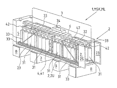
Fig. 1 is a perspective view of an embodiment of the energy storage module 1
according to the invention. The mobile energy storage module 1 has an
enclosing
module housing 2 which, in the illustrated instance, is only indicated to
simplify
matters and provide a view of the modules inside the module housing. In this
embodiment, the module housing has the form of a longitudinal cuboid with four
side surfaces 2S, a top side 20 (not shown) and a bottom side 2U the edge of
which is visible. One of the side surfaces 2S is designed as a door in order
that
the modules 3, 4, 5 can be accommodated in the module housing 2 and be
removed again if necessary. If necessary, the door also provides access to the
energy storage module 1 for maintenance personnel. A flywheel module 3 having
a total of twenty-eight flywheel energy storage units 31 is arranged in the
module
housing 2, the flywheel energy storage units 31 being connected via a DC link
32
for providing a common module storage capacity MSK and module output ML.
The number of flywheel energy storage modules 31 is adjusted such that the
energy storage module 1 can release electric current into a non-local power
supply grid NS via the module capacity MSK and module output ML thus provided
for a time period of more than 30 s. Therein, the individual flywheel energy
storage units 31 can transfer an output of 20 kW on an average. As a result,
this
energy storage module 1 has a module storage capacity of 560 kW. The number
of flywheel energy storage units 31 in an energy storage module 1 may vary
from
energy storage module to energy storage module_ A high number of flywheel
energy storage units 31 per energy storage module 1 is to advantage in that it
increases the module storage capacity MSK and module output ML of the energy
storage module I. Therein, the rotational axis of the cylindrical rotors of
the
flywheel energy storage units 31 extends vertically to the surface on which
the
module housing 2 is set up, in the illustrated instance shown as a concrete
foundation B that is subdivided into four parts. In other embodiments,
however,
the module housing 2 can also be positioned on a smoothed and, if necessary,
hardened ground B. Therein, the flywheel energy storage units 31 are mounted
to
a frame 33 which also supports the bearings of the flywheel energy storage
units
31. The form of the frame 33 shown in the illustrated instance is adjusted to
the
CA 02886100 2015-03-25
29
form of the module housing 2 and of the door at the end of the module housing
2,
with the result that the flywheel module 3 consisting of the frame 33 and the
flywheel energy storage units 31 and the DC link 32 can be inserted into and
removed from the module housing 2 as a whole. The frame comprises vertical
.. posts at each quarter of the length of the module housing, which are
connected to
the opposite posts through horizontal frame parts on the top and bottom sides
in
the module housing, in order to each form a rectangular frame running around
the
cross-section of the module housing. These rectangular frames that are five in
total are connected to each other via horizontal beams along the longitudinal
direction of the module housing 2 at the top and bottom on each longitudinal
side.
The resulting frame shape forms an open cuboid within the module housing 2
wherein the flywheel energy storage units 31 are held and mounted between the
upper and lower beams on each side. Therein, the flywheel energy storage units
31 are mounted to the frame 33 of the flywheel module 3 such that the
mechanical
.. energy of an individual flywheel energy storage unit 31 can be discharged
through
structural components disposed in the frame 33 in the event of an
extraordinary
failure such that neighboring flywheel energy storage units 31 cannot be
affected
during operation. To achieve this, the neighboring flywheel energy storage
units
31 are arranged side by side and spaced apart by an appropriate distance. In
this
.. embodiment, the vacuum module 4 is arranged centrally in the module housing
2,
at least with the vacuum pump stage 41 which is connected to the individual
flywheel energy storage units 31 of the flywheel module 3 via a pipe system 42
in
order to evacuate the rotor container in the flywheel energy storage units 31.
On
the inside of the module housing 2, the module housing 2 has an insulation
layer
23 that is indicated in the vicinity of the ground and the vicinity of the
door. The
insulation layer 23 allows generating a controlled indoor temperature in the
module housing 2 in cooperation with the cooling module 5. The cooling module
5
is indicated schematically and is supposed to discharge internal thermal loads
developing during operation of the flywheel module 3 from the module housing 2
to the outside. Therein, the module housing 2 can be made of metal, preferably
of
steel, to represent a robust shell for transporting and operating the energy
storage
module. Dimensions can be adjusted to the application and to the form of the
modules in the module housing 2. Preferably, the module housing 2 has a
CA 02886100 2015-03-25
standardized form in order that it can be transported with the transport means
available and does not require any special treatment for transport.
Preferably, the
module housing 2 is an ISO container as it is shown in the illustrated
instance.
Furthermore, the module housing 2 comprises a module control system 6 that is
5 provided for appropriately controlling the modules 3, 4, 5 and, where
applicable,
further modules in the module housing 2 that are not shown in the illustrated
instance, in order to allow carrying out control and system tasks in power
supply
grids. To achieve this, the modules 3, 4, 5 and the module control system 6
are
connected to each other via a data bus 61 (without illustration) in order that
the
10 module control system 6 can transmit the control commands to the
respective
modules 3, 4, 5 for the purpose of their implementation.
Fig. 2 is a schematic perspective view of the module housing 2 of the energy
storage module 1 shown in Fig. 1, having a top side 20, a bottom side 2U and
15 four side surfaces 2S. In addition, the module housing 2 is designed such
that it is
windproof and watertight (closed side surfaces 2S, bottom side 2U and top side
20). Three power connection interfaces 21a, 21b, 21c are each arranged on the
forward side surface 2S of the module housing 2, for example, for connection
to a
local and/or non-local power supply grid LS, NS in order to carry out the
control
20 and system tasks and to supply the modules in the module housing 2 with
current.
The likewise three data interfaces 22a, 22b, 22c are provided to receive EM at
least the control and system tasks ORS, NORS to be carried out in the
connected
power supply grids as external data ED and to send operating data BD to the
outside. The presence of three interfaces allows achieving redundancy by using
25 different communication networks for communication. On the bottom side 2U
of
the module housing 2, ground fixing means 24 for reliably and reversibly
anchoring the energy storage module 1 to the ground B are arranged in the four
corners of the bottom side 2U. in the embodiment shown in the illustrated
instance, the ground fixing means 24 are earth anchors in order that the
energy
30 storage module can be positioned on a foundation and has nevertheless a
stability appropriate for operation so that the static and dynamic loads of
the
flywheel energy storage units "1 can be discharged into the ground during
operation. Due to the weight of the energy storage module 1, the earth anchors
24
CA 02886100 2015-03-25
31
penetrate into the ground B over their full length, thereby giving the module
housing 2 a considerable stability.
Fig. 3 is a schematic representation of the energy storage module 1 according
to
the invention, comprising the internal connectors and data connections. To
simplify matters, the energy storage module 1 according to this embodiment is
shown with only four flywheel energy storage units 31 for the reversible
storage of
energy. In contrast, energy storage modules 1 intended for real operation
comprise a considerably greater number of flywheel energy storage units 31.
The
flywheel energy storage units are switched in parallel via a DC link 32 which,
in
the illustrated instance, is configured as a common DC bus 32 which is
connected
to one or more power converters 34 or forward converters 34.
The individual modules of the energy storage module are connected to each
other
via the data line 61, for example, a data bus 61. A local power supply grid LS
is
connected to the energy storage module 1 via the power connection interface
21c,
and a non-local power supply grid NS is connected to the energy storage module
1 via the power connection interface 21b. The non-local power supply grid NS
is
additionally connected to the power connection interface 21a in order that the
energy storage module 1 is supplied with the operating current required for
the
modules (internal power lines are not explicitly shown in the illustrated
instance).
In order that the energy released Ep from the flywheel module 3 can be fed
into
the two connection power supply grids LS, NS in a properly distributed manner,
the energy storage module 1 comprises a regulating unit 7, which is described
in
detail in Figure 5, for splitting the energy flow into separate energy flows
EFg and
EFI into the separate power supply grids LS and NS. As a result, the complete
module storage capacity MSK and the module output ML can be used for energy
absorption En from and energy release Ep to one or more power supply grids NS,
LS that is/are connected to the energy storage module 1. In an energy storage
module 1 that is only connected to a local power supply grid LS connected to
the
non-local power supply grid NS, the regulating unit 7 comprises at least one
circuit breaker. In this case, it is not necessary to split the energy flows
because
the complete energy flow EF ends in the local power supply grid LS.
Alternatively,
the system can also be equipped with a second or more additional forward
CA 02886100 2015-03-25
32
converter(s) 34 and a second or a more additional circuit breaker(s) 7. In
this
case, the regulating box 7 can be omitted, where applicable. The energy
storage
module 1 comprises an interface 22a (to simplify matters, only one out of more
than one potential data interfaces is shown in the illustrated instance) to
receive
EM external data ED regarding the localized and non-localized control and
system tasks ORS, NORS to be carried out and a module control system 6 for
storing Sand carrying out AO, ANO the external data (control commands). The
data interface 22a is also used to send operating data BD and/or a test signal
TS
to the outside in order to check an existing communication connection.
Accordingly, the data interface 22a receives a corresponding return signal RS.
In
order to carry out ANO the non-localized control and system tasks NORS in the
local power supply grid NS, the module control system 6, herein, has the
module
storage capacities MSK and module outputs ML only within the scope of the
portions of the module storage capacities MSK and/or module output ML that are
not required for carrying out AO the localized control and system tasks ORS.
To
achieve this, the module control system 6 comprises a priority management unit
64 for carrying out AO, ANC the individual external data ED (control
commands),
wherein carrying out AO the external data ED (control commands) regarding
localized control and system tasks ORS in the local power supply grid LS has
priority over carrying out ANO the external data ED (control commands)
regarding
non-localized control and system tasks NORS in the non-local power supply grid
NS. This priority management unit 64 is, for example, designed as a data
memory
with a priority hierarchy stored therefrom. The priority hierarchy can be
available
in the form of a file which can, for example, be replaced or modified on site.
In one
embodiment, it is provided that, for system safety reasons, it is not possible
to
access the priority management unit 64 via the data interface 22a. Inter alia,
the
control is effected in that the module control system 6 tells the individual
flywheel
energy storage units 31 how much energy should be released by means of
deceleration or be absorbed by means of acceleration, and in that the
regulating
unit 7 is appropriately activated by transmitting configuration data KD for
the
regulating function. Furthermore, the module control system comprises a task
memory 63 in which the received EM external data ED about the control and
system tasks to be carried out are stored. Prior to storage, the external ED
may
CA 02886100 2015-03-25
33
be checked for origin and content, said storage being refused if necessary in
case
the check fails to be successful. The module control system 6 can access the
task
memory 63 and create an operating plan BP according to the external data ED
and the priorities in the priority management unit 64. The energy storage
module
1 will then be controlled according to the operating plan BP created. The
operating plan can also comprise instructions for activating the cooling
module 5
and the vacuum module 4. The vacuum module is connected to the rotor housings
of the flywheel energy storage units 31 via the pipe system 42 (shown in
black)
and generates the required operating vacuum by means of a vacuum pump stage
41 that is connected to the pipe system 42 and can, for example, comprise a
booster pump and a turbomolecular pump. In order to carry out AO, ANO the
localized and non-localized control and system tasks ORS, NORS in the local
and
non-local power supply grids LS, NS, the energy storage module 1 uses one or
more measuring units 62 to measure relevant data RD in the connected power
supply grids LS, NS and uses these relevant data RD as a basis for carrying
out
AO, ANO (shown as a dashed =Irrow to the module control system 6).
Fig. 4 shows an exemplary embodiment of the energy storage system 10
according to the invention. In this embodiment, the energy storage system 10
has
three energy storage modules 1, 1', 1" each having a flywheel module 3 for
reversible storage of energy per energy storage module 1, 1', 1'' each having
a
module storage capacity MSK and a module output ML. The three energy storage
modules 1, 1', 1" are subdivided into a master module with a master control
system 6M for controlling the energy storage system 10 and two slave control
system 6S in the energy storage modules 1, 1". The embodiment shown here is
only exemplary. The number of energy storage modules per energy storage
system 10 depends on the particular application desired and can therefore vary
strongly. In the illustrated instance, the energy storage modules 1, 1, 1" are
connected via a common connection point 9, with the result that their module
capacities MSK and module outputs ML are available in total as the system
storage capacity ASK and system output AL of the energy storage system 10 for
control and system tasks NORS, ORS. The energy storage modules 1, 1', 1" are
connected to each other via a data network 8, for example, a data bus 8.
Therein,
CA 02886100 2015-03-25
34
this data network 8 can be extended in order that additional energy storage
modules 1¨ can be added to the existing three energy storage modules 1, 1', 1"
at
a later point if necessary. The same applies to the power connection 21a at
the
common connection point 9. The energy storage modules comprise one or more
power connections 21a, 21b, 21c (the latter two are not shown in the
illustrated
instance) which, in this embodiment, are connected via a common connection
point 9 for connection to the power supply grids LS, NS. Via the connection
point,
the non-localized control and system tasks NORS in the non-local power supply
grid NS and the localized control and system tasks ORS in the local power
supply
grid LS can be carried out by energy absorption En from and energy release Ep
to
the connected power supply grid(s) LS, NS. To split the energy flow EF into
separate energy flows EFg, EFI to the separate power supply grids NS, LS at
the
connection point, the energy storage system 10 comprises a regulating unit 7
(see
also Fig. 5). As a result, the complete system storage capacity ASK and the
system output AL can be used for energy absorption En from and energy release
Ep to one or more power supply grids NS, LS that is/are connected to the
energy
storage system 10. In an energy storage system 10 that is only connected to a
local power supply grid LS connected to the non-local power supply grid NS,
the
regulating unit 7 comprises at least one circuit breaker. In this case, it is
not
necessary to split the energy flows EF because the complete energy flow EF
ends
in the local power supply grid LS. The master control system 6M is designed
for
overall control of all of the energy storage modules 1, 1', 1" connected to
the data
network 8 and comprises at least one data interface 222 for receiving EM
external
data ED (control commands) regarding the localized and non-localized control
and system tasks ORS, NORS to be carried out. In order to carry out AO, ANO
the control and system tasks ORS, NORS, the master control system 6M has the
module storage capacities MSK and module outputs ML of all of the energy
storage modules 1, 1', 1" connected to it and, therein, carries out ANO the
non-
localized control and system tasks NORS only within the scope of the portions
of
the system storage capacities ASK and/or system output AL that are not
required
for the localized control and system tasks ORS. The components of the master
control system 6M can be seen in detail in Figure 3. In this embodiment, the
other
energy storage modules 1', 1" (also referred to as slave modules) each
comprise
CA 02886100 2015-03-25
one slave control system 6S that monitors and controls the operating states BZ
of
the respective slave module 1', 1" and transmits to the master control system
6M
the operating data BD of the slave modules 1', 1" via the data network 8.
Here,
the slave modules 1', 1" are jointly controlled by the master control system
6M by
5 the latter instructing the slave control units 6S to carry out the
control and system
tasks ORS, NORS and the individual slave control units 6S implementing the
instructions into corresponding machine parameters for the flywheel energy
storage units 31. The control is effected in that the master control system 6M
tells
the individual energy storage modules 1, 1, 1" how much energy should be
10 released from the flywheel energy storage units 31 by means of
deceleration or
be absorbed in the individual flywheel energy storage units 31 by means of
acceleration. In order to ensure that this energy absorption or release can be
achieved as desired, the slave control units 6S thereupon control the drive
motors
of the flywheel energy storage units 31 such that they decelerate or
accelerate the
15 .. individual flywheel energy storage units 31.
Fig. 5 shows an exemplary embodiment of the regulating unit 7 which, in the
illustrated instance, is connected to a local power supply grid LS and to a
non-
local power supply grid NS. In order that the regulating unit 7 can regulate
the
20 energy flow EF between the connected power supply grids LS, NS and the
energy
storage module 1 or the energy storage system 10 and, if necessary, disconnect
one or more connected power supply grids, i.e. the local power supply grid LS
and/or the non-local power supply grid NS in the illustrated instance, from
the
energy storage module 1 or the local energy storage system 10, the regulating
25 unit 7 according to this embodiment comprises a regulating box 71 having
a
control element 71-1 and separate circuit breakers 71-2 for each of the
connected
power supply grids LS, NS. The master control unit 6 (master control system
6M)
is connected to the control element 71-1 of the regulating box 71 via a data
connection 61 (or a data network 8) and transmits appropriate configuration
data
30 .. of the regulating function KD to the regulating box 71, i.e. directly to
the control
box 71-1 in the illustrated instance, for controlling the energy flows. Based
on the
configuration data of the regulating function KD, the control element 71-1
controls
the splitting of the energy flow EF coming in from the connection point 9 to
the
CA 02886100 2015-03-25
36
connected power supply grids LS, NS into the energy flow ER for the local
power
supply grid LS and the energy flow EFg for the non-local power supply grid NS.
In
this exemplary embodiment, the distribution of the energy flow EF is shown
when
energy is fed into both connected power supply grids LS, NS by way of example
only. Similarly, the regulating box 71 is configured to control an energy flow
from
one of the connected power supply grids LS, NS and an energy flow to the other
one of the connected power supply grids LS, NS wherein, depending on the size
of the two energy flows, either the negative energy excess of the energy
storage
module 1 or the energy storage system 10 is stored or the positive energy
excess
.. of the energy storage module 1 or the energy storage system 10 is provided.
In
the illustrated instance, the energy storage module 1 or the energy storage
system 10 is not shown explicitly but only symbolically through the
corresponding
components 6, 6M, 61, 62, 7, 8. The regulating box 71 simultaneously receives
the relevant data RD of the two connected power supply grids LS, NS from
.. corresponding measuring units 62 wherein, based on said relevant data RD,
the
control element 71-1 derives the presence of the two connected power supply
grids LS, NS by means of criteria or threshold values for the relevant data RD
that
are filed in the control element 71-1. If one or either of the connected power
supply grids LS, NS is no longer available because of a grid failure, the
failure of
the particular power supply grid LS, NS manifests itself in the corresponding
relevant data RD transmitted to the control element 71-1, whereupon the
control
element 71-1 automatically sends appropriate disconnection instructions
(dashed
arrow) to the respective circuit breaker(s) 72-2 for disconnection of the
energy
storage system 10 from the connected power supply grid(s) LS, NS, whereupon
the circuit breaker(s) 71-2 disconnect(s) the previously connected power
supply
grid(s) LS, NS from the energy storage module 1 or the energy storage system
10.
Therein, the connected power supply grid is disconnected within a few
milliseconds. If only one power supply grid LS or NS is disconnected, the
energy
storage module 1 or the energy storage system 10 continues to be ready for the
.. other still connected power supply grids. As a result, a short-circuit or
overload
situation can effectively be prevented in the event of a failure of the power
supply
grid LS or NS. The exemplary embodiment shown here with a connected local
power supply grid LS and a connected non-local power supply grid NS is only an
CA 02886100 2015-03-25
37
example for two connected power supply grids. In other embodiments, the
regulating unit 7, more particularly the regulating box 71, can also be
connected
to more than two power supply grids. The two or more connected power supply
grids can also each be local power supply grids out of which at least one of
the
local power supply grids is connected to the non-local power supply grid for
carrying out the non-localized control and system tasks.
Fig. 6 shows an embodiment of the method according to the invention for
providing localized and non-localized energies for control and system tasks
ORS,
NORS in a variable mariner. At first, the system storage capacity ASK and
system
output AL required for carrying out AO, ANO the desired control and system
tasks
ORS, NORS are determined BS in the particular power supply grids LS, NS to be
connected. Thereafter, an appropriate number of energy storage modules 1, 1',
1"
according to the invention having respective module storage capacities MSK,
module outputs ML and module control systems 6 are set up AF at an
installation
site, wherein the number of energy storage modules 1, 1', 1" is selected such
that
the sum total of all module storage capacities MSK and module outputs ML
corresponds to the required system storage capacity ASK and system output AL.
Prior to operation, the module housings 2 of the energy storage modules 1, 1,
1"
are anchored VA to the ground B of the installation site in order that they
can
absorb the static and dynamic loads during operation of the energy storage
system 10. Furthermore, the energy storage modules 1, 1', 1" are connected ASM
in a common connection point 9 and the connection point 9 is connected ASS to
the respective power supply grids LS, NS. Likewise, the energy storage modules
1, 1', 1" are connected VB to each other by means of a common data network 8
to
form a common energy storage system 10, with the result that this allows
common
control GS of the energy storage system via the respective module control
systems 6. If the demand for carrying out control and system tasks in the
connected power supply grids LS, NS changes in the course of time, the energy
storage system 10 can be adjusted AP to the changed demand for system storage
capacity ASK and system output AL in an appropriate manner by adding H further
energy storage modules 1" according to the aforementioned method steps or by
removing E one or more energy storage modules 1" from the energy storage
CA 02886100 2015-03-25
38
system 10 after all power connections 21a, 21b, 21c for the particular energy
storage module 1" to be removed have been disconnected from the connection
point 9, all data interfaces 22a, 22b, 22c have been disconnected from the
data
network 8 and the module housing 2 has been detached from the installation
site.
The embodiments shown here represent only examples of the present invention
and may therefore not be understood to be limiting. Alternative embodiments
that
can be contemplated by the person skilled in the art are likewise included in
the
scope of the present invention.
CA 02886100 2015-03-25
39
List of reference symbols
=
1 Energy storage module according to the invention
1', 1, 1'" Further energy storage modules according to the invention
10 Energy storage system having more than one energy storage
modules according to the invention
2 Module housing
2U Bottom side of the module housing
2S Side surface of the module housing
20 Top sides of the module housing
21a, 21b, 21c Power connection interface
22a, 22b, 22c Data interfaces
23 Insulation layer
24 Ground fixing means
3 Flywheel module
31 Flywheel energy storage unit
32 DC link
33 (Mounting) frame for the flywheel energy storage units
34 Power converter or forward converter
4 Vacuum module
41 Vacuum pump stage
42 Pipe system
5 Cooling module
6 Module control system
6M Master control system (leading module control system)
6S Slave control system (dependent module control system)
61 Data bus (in the energy storage module or between different
energy storage modules)
62 Measuring unit
63 Task memory
64 Priority management unit
CA 02886100 2015-03-25
7 Regulating unit (in the energy storage module or in the energy
storage system outside the energy storage modules)
71 Regulating box
5 71-1 Control element
71-2 Circuit breaker
8 Data network for connecting different energy storage modules
according to the invention
9 Connection point
AF Setting up a number of energy storage modules at installation
sites
AL System output of the energy storage system
ANO Carrying out the non-localized control and system tasks
AO Carrying out the localized control and system tasks
AP Adjusting the energy storage system to a changed demand for
system storage capacity and system output
ASK System storage capacity of the energy storage system
ASM Connecting the energy storage modules to a common connection
point
ASS Connecting the connection point to the power supply grids
Ground, foundation
BD Operating data
BP Operating plan
BS Determining the required system storage capacity and system
= output
Removing an energy storage module from an energy storage
system
ED External data (control commands)
EF Energy flow
EFg Energy flow portion for the non-local power supply grid
EFI Energy flow portion for the local power supply grid
EM Receiving data (external data)
En Absorption of energy from the power supply grid (negative
energy)
Ep Release of energy to the power supply grid (positive energy)
CA 02886100 2015-03-25
41
GS Common control of the energy storage system
Adding energy storage module(s) to the energy storage system
KD Configuration data of the regulating function
LS Local power supply grid
ML Module output
MSK Module storage capacity =
NORS Non-localized control and system tasks
NS Non-local power supply grid
ORS Localized control and system tasks
RD Relevant data
RS Return signal
TS Test signal
VA Anchoring the module housing to the ground at the installation
site
VB Connecting the energy storage module by means of a common
data network