Note: Descriptions are shown in the official language in which they were submitted.
CA 02886292 2015-03-26
ELECTRONIC CIGARETTE AND ELECTRONIC CIGARETTE DEVICE THEREOF
FIELD OF THE INVENTION
[0001] The present invention relates to electronic cigarettes and cigarette
box, especially an
electronic cigarette and electronic cigarette device with a one-way valve
mechanism capable of
controlling the direction of airflow.
BACKGROUND OF THE INVENTION
[0002] With further understanding of the harm of smoking by people, quit
smoking has become
the common goal of most smokers. Then, as a substitute for cigarette,
electronic cigarette is
gradually welcomed by people.
[0003] Current electronic cigarette is usually composed of two parts,
including an inhalation rod
and a battery rod, wherein the inhalation rod usually disposes a suction
nozzle and an atomization
device operable to make cigarette liquid into aerosol. The battery rod usually
disposes a battery and
a control switch therein. The battery is used to supply power, and the control
switch is used to
control the overall operation of the electronic cigarette. Air path of current
electronic cigarette is
completely through in both inhaling and blowing conditions. When the user
blowing to the
electronic cigarette, the aerosol and cigarette liquid in the atomization
device always flow to the
battery and the control switch driven by action of airflow, leading to
resistance of the battery
increasing and electrode oxidation, and then cause short circuit, the control
switch failure and so on.
SUMMARY OF THE INVENTION
[0004] The objective of the present invention is: to provide an electronic
cigarette, which has the
. 25 function of one-way air path control capable of communicating the
air path when inhalation and
blocking the air path when blowing.
[0005] To achieve the aforementioned objective, the present invention
discloses an electronic
cigarette including a main rod body. One end of the main rod body disposes a
suction nozzle, and
the other end of the main rod body disposes a battery. The main rod body also
disposes a one-way
1
CA 02886292 2015-03-26
valve used to communicate an air path when inhalation and block the air path
when blowing, and is
located between the suction nozzle and the battery. The one-way valve
comprises a valve seat with
both ends throughout, a valve core and a valve flap installed in the valve
seat. The valve seat or the
valve core disposes a gas guide hole thereon. The valve flap is attached at a
port of one end of the
gas guide hole and used to control open and close state of the gas guide hole
according to
corresponding elastic deformation generated by inhalation or blowing
operations.
[0006] Furthermore, the valve flap comprises a sheet body which is sheet-
shaped and, of which the
area is bigger than the cross section of the gas guide hole and capable of
completely covering the
port of one end of the gas guide hole, and a connecting portion locating at
one side edge of the sheet
body and elastically connected to the valve seat or the valve core.
[0007] Furthermore, the valve flap is disposes on an outside of the port of
one end of the gas
guide hole near the suction nozzle.
[0008] Furthermore, one end of the valve seat disposes a valve core-
accommodating groove
matching with the outer contour of the valve core, the valve core is embedded
in the valve core-
accommodating groove.
[0009] Furthermore, the valve flap is made of soft plastic material.
[0010] Furthermore, one end of the main rod body near the suction nozzle
further disposes an
atomization device electrically connecting with the battery.
[0011] Furthermore, the one-way valve is disposed between the suction nozzle
and the atomization
device.
[0012] Furthermore, the one-way valve is disposed between the battery and the
atomization device,
and one end of the valve seat near the battery disposes vent hole along radial
direction
communicating with the gas guide hole.
[0013] Furthermore, the atomization device disposes a heating wire used to
vaporize the cigarette
liquid, the valve seat and the valve core disposes wire-through hole for the
two ends of the heating
wire passing through.
[0014] Furthermore, the other end of the electronic cigarette away from the
suction nozzle disposes
a light-emitting device, the light-emitting device comprises a light-emitting
unit electrically
connecting with the battery and a light cap covering the outer of the light-
emitting unit.
2
CA 02886292 2015-03-26
=
[0015] Furthermore, at the connection between the light cap and the main rod
body disposes an air
inlet communicating with the gas guide hole.
[0016] Furthermore, on the sidewall of the main rod body corresponding to the
battery near one
end of the suction nozzle disposes an air inlet communicating with the gas
guide hole.
[0017] Furthermore, the electronic cigarette further includes an atomization
control unit electrically
connecting with the battery to control the power-on or power-off for the
atomization device, the
atomization control unit comprises an atomization control circuit and an
atomization control switch
which is connected with the atomization control circuit.
[0018] Furthermore, the atomization control switch is a capacitive sensor
switch or a airflow sensor
switch.
[0019] A further objective of the present invention is: to provide an
electronic cigarette device, in
which electronic cigarette is disposed and has the function of one-way air
path control.
[0020] To achieve the aforementioned objective, the present invention also
disclose an electronic
cigarette device, including an electronic cigarette box and an electronic
cigarettes accommodated in
the electronic cigarette box. The electronic cigarette is the electronic
cigarette as described above.
[0021] The advantages of the embodiments of the present invention is: due to
dispose the one-way
valve between the suction nozzle and battery of the electronic cigarette,
making the electronic
cigarette have the function of one-way air path control capable of
communicating the air path when
inhalation and blocking the air path when blowing.
[0022] Embodiments of the present invention will be further described in
detail in the following
drawings.
BRIEF DESCRIPTION OF THE DRAWINGS
[0023] FIG. 1 is an exploded, isometric view of an electronic cigarette
according to a first
embodiment of the present invention.
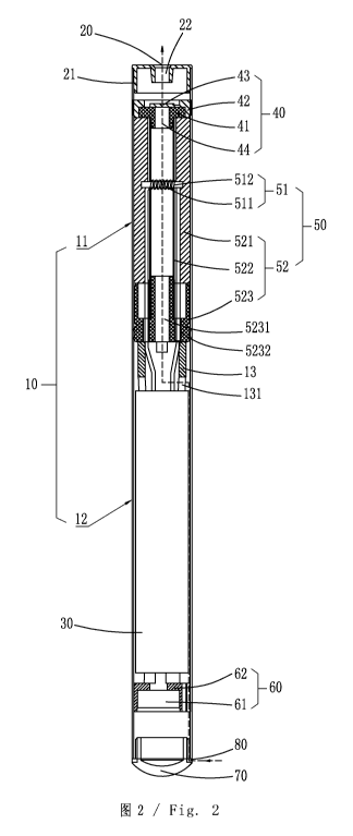
[0024] FIG. 2 is a sectional view of an electronic cigarette according to the
embodiment of the
present invention.
3
CA 02886292 2015-03-26
[0025] FIG. 3 is an exploded, isometric view of an electronic cigarette
according to a second
embodiment of the present invention.
[0026] FIG. 4 is a sectional view of an electronic cigarette according to the
second embodiment of
the present invention.
[0027] FIG. 5 is a sectional view of an electronic cigarette according to a
third embodiment of the
present invention.
[0028] FIG. 6 is an exploded, isometric view of a one-way valve of an
electronic cigarette
according to a first embodiment of the present invention.
[0029] FIG. 7 is a schematic view of Valve flap, the one-way valve of an
electronic cigarette
according to the first embodiment of the present invention, showing a valve
flap being close state.
[0030] FIG. 8 is a schematic view of the one-way valve of an electronic
cigarette according to the
first embodiment of the present invention, showing a valve flap being open
state.
[0031] FIG. 9 is an exploded, isometric view of a one-way valve of an
electronic cigarette
according to a second embodiment of the present invention.
[0032] FIG. 10 is a schematic view of the one-way valve of an electronic
cigarette according to the
first embodiment of the present invention, showing a valve flap being close
state.
[0033] FIG. 11 is a schematic view of the one-way valve of an electronic
cigarette according to the
first embodiment of the present invention, showing a valve flap being open
state.
[0034] FIG. 12 is an isometric view of an electronic cigarette device
according to a embodiment of
the present invention.
DETAILED DESCRIPTION OF THE INVENTION
[0035] Referring to FIG. 1 to FIG. 12, the embodiment of the present invention
provides an
electronic cigarette device including an electronic cigarette 100 capable of
one-way air path
controlling and an electronic cigarette box 200 operable to accommodate the
electronic cigarette
100.
[0036] Referring to FIG. 1 and FIG. 3, the electronic cigarette 100 includes a
main rod body 10.
The main rod body 10 is disposed as cylindrical tube structure, and is hollow
inside thereof to form
4
CA 02886292 2015-03-26
an accommodating chamber for all kinds of internal components. It is
understood that the main rod
body 10 also can be disposed as any other tubular structure arranged with a
hollow chamber, but not
limited to the cylinder shown in the embodiment. In the embodiment, the main
rod body 10 can be
made of stainless materials, and also can be made of plastic or other
applicable materials.
[0037] Referring to FIG. 2, FIG. 4 and FIG. 5, one end of the main rod body 10
disposes a suction
nozzle 20, and the other end of the main rod body 10 away from the suction
nozzle 20 disposes a
battery 30. Therefore, according to the composition of the internal components
in the main rod body
10, the main rod body 10 may be divided into two parts as an inhalation rod 11
and a battery rod 12.
That is, the main rod body 10 includes the inhalation rod 11 and the battery
rod 12 which are
mutual butted. In the embodiment, the inhalation rod 11 and the battery rod 12
are designed as
undetachable integral structure. As an alternative embodiment, the inhalation
rod 11 and the battery
rod 12 also can be disposed as a detachably connected, for example, by
clamping connection,
inserted connection or screwed connection and etc.
[0038] The battery 30 is disposed in the battery rod 12 operable to supply
power for every function
module of the electronic cigarette 100. The suction nozzle 20 is arranged at
the other end of the
inhalation rod 11 away from the battery 30. In the embodiment, the suction
nozzle 20 includes the
inhalation cover 21 sheathed on one end of the inhalation rod 11. The
inhalation cover 21 axially
defines an inhalation hole 22.
[0039] Referring to FIG. Ito FIG. 5, the main rod body 10 disposes an air path
of the electronic
cigarette 100 throughout the main rod body 10 inside thereof. Between the
suction nozzle 20 and
the battery 30 disposes a one-way valve 40 operable to control the state of
the air path according to
inhaling or exhaling; that is to communicate the air path when inhaling and
block the air path when
exhaling.
[0040] Specifically, the one-way valve 40 includes a valve core 41, a valve
seat 42 and a valve flap
43. Two ends of the valve seat 42 are throughout. The valve core 41 is
disposed in the valve seat 42.
The valve seat 42 or the valve core 41 disposes a gas guide hole 44. The valve
flap 43 is detachably
place at one open end of the gas guide hole 44 and operable to control the
open and close state of
the gas guide hole 44 according to the inhaling or exhaling operations which
makes elastic
deformation thereof. When the user inhales at the suction nozzle 20, negative
air pressure is formed
at one side of the valve flap 43 facing the suction nozzle 20, air pressure at
the other side of the
valve flap 43 pushes the valve flap 43 to the suction nozzle 20 and to leave
away from the gas guide
hole 44, thereby the gas guide hole 44 is opened and communicated to the
suction nozzle 20, smoke
5
CA 02886292 2015-03-26
can flow to the suction nozzle 20 for the user smoking. When the user exhales,
the air pressure
from the suction nozzle 20 pushes the valve flap 43 to close the gas guide
hole 44, thus the air path
of the electronic cigarette 100 is disconnected, and the smoke will not be
blown to the battery 30.
[0041] Referring to FIG. 6 to FIG. 8, the valve flap 43 is removably disposed
at an outside of the
port of the gas guide hole 44 near the suction nozzle 20, and can be disposed
on the valve core 41 or
the valve seat 41 according to the direction of the one-way valve 40. The
valve flap 43 includes a
sheet body 431 which is thin-sheet shaped and of which the area is larger than
that of the port of the
gas guide hole 44 so as to completely cover the port of the gas guide hole 44,
and a connecting
portion 432 located at one side edge of the sheet body 431 and elastically
connected to the valve
core 41 or the valve seat 42. In the embodiment, the valve flap 43 may be
integrated with the valve
core 41 or the valve seat 42. The sheet body 431 is configured as a circular
shape of which a
diameter is bigger than that of the port of the gas guide hole 44 so as to be
capable of completely
covering the port of the gas guide hole 44. It is understood that the sheet
body 431 of the valve flap
43 also may has a square shape, polygonal or other shape with an ability of
completely covering the
gas guide hole 44 to close the air path when the valve flap 43 attaching to
the gas guide hole 44. As
an embodiment, the valve flap 43 may be separated from the valve core 41 or
the valve seat 42, for
example, the connecting portion 432 of the valve flap 43 is firmly fixed
between the valve seat 42
and the valve core 41 by clamping connection, inserting connection or other
available connection
methods.
[0042] In the embodiment, the valve flap 43 is made of soft plastic materials
such as rubber,
silicone rubber, thermoplastic polyurethane elastic plastic and etc, so that
the valve flap 43 has an
ability of elastic deformation under airflow pressure to switch the air path
open or close.
[0043] In a first embodiment as shown in FIG. 6 to FIG. 8, the valve flap 43
is disposed on the
valve seat 42, and the gas guide hole 44 is defined in the valve core 41.
Specifically, the valve seat
42 has one side thereof near the valve core 41 forming a valve core-
accommodating groove 420 to
match with the outer contour of the valve core 41 and sheath the valve core
41, and has it bottom
defined a valve flap- accommodating cavity 422 . The valve core 41 is embedded
in the valve core-
accommodating groove 420. The valve flap 43 is attached on the outer surface
of the valve core 41
and covers the gas guide hole 44. Referring to FIG. 7 and FIG .8, the
direction of the arrow as
shown in the figures is airflow direction. When airflow flows from the valve
seat 42 toward the
valve core 41, the valve flap 43 is firmly attached on the outside of the port
of the gas guide hole 44
under the airflow pressure, then the gas guide hole 44 is closed and the air
path is blocked; When
6
CA 02886292 2015-03-26
airflow flows from the valve core 41 toward the valve seat 42, the valve flap
43 generates elastic
deformation under the airflow pressure, and the sheet body 431 leaves away
from the inner wall of
the bottom of the valve seat 42, separates from the valve core 41 and
gradually leaves away from
the gas guide hole 44, then finally achieves the communication of the air
path. In this embodiment,
the valve core 41 and the valve seat 42 respectively has an annular shape. The
seat 42 includes an
annular side wall 424 which encloses the valve core 41 and forms the valve
core-accommodating
groove 420 therein, and an annular bottom wall 426 which defines the valve
flap-accommodating
cavity 422.
[0044] In a second embodiment as shown in FIG. 9 to FIG. 11, in the
embodiment, the valve flap
43 is disposed on the valve core 41, and the gas guide hole 44 is defined in
the valve seat 42. One
side of the valve seat 42 near the valve core 41 forms a valve core-
accommodating groove 420
which matches with the outer contour of the valve core 41 and sheaths on the
valve core 41. The
valve core 41 is embedded in the valve core-accommodating groove 420. The
valve flap 43 locates
at one side of the valve core 41 near to the valve seat 42 and is attached on
the inner surface of the
valve core-accommodating groove 420 and completely covers the port of the gas
guide hole 44.
Referring to FIG. 10 and FIG. 11, the direction of the arrow as shown in the
figures is airflow
direction. When airflow flows from the valve core 41 toward the valve seat 42,
the valve flap 43 is
firmly attached on the outside of the port of one end of the gas guide hole 44
under the airflow
pressure, then the gas guide hole 44 is closed and the air path is blocked.
When airflow flows from
the valve seat 42 toward the valve core 41, the valve flap 43 generates
elastic deformation under the
airflow pressure, and the sheet body 431 separates from the valve seat 42 and
gradually moves
away from the gas guide hole 44, then finally achieves the communication of
the air path. In this
embodiment, the valve core 41 is an annular structure, defines a valve flap-
accommodating cavity
412 for accommodating the valve flap 43. The valve seat with a cylindrical
structure comprises an
annular side wall 424 defining the valve core-accommodating groove 420, a
bottom wall 426
defining the gas guide hole 44 therethrough, and another annular side wall 425
opposite to the
annular side wall 424 and together with the bottom wall 426 to form a civility
(not labeled)
communicated with the gas guide hole 44. The annular side wall 425 defines a
cut or a through
hole as a vent hole 46 to prevent air path blockage. There are a couple of
vent holes 46 in this
embodiment. The valve core 41 and the valve seat 42 define wire-through holes
45
[0045] Referring to FIG. 1 to FIG. 5, in the main rod body 10 also is set with
an atomization device
50 therein operable to vaporize cigarette liquid into aerosol. In the
embodiment, the atomization
7
CA 02886292 2015-03-26
= .
device 50 is disposed in the inhalation rod 11 of the main rod body 10, and
includes an atomizer 51
and an atomization cup 52 used to accommodate the atomizer 51.
[0046] The atomizer 51 is used to vaporize cigarette liquid into aerosol, and
includes a heating wire
511 and a liquid-guiding member such as fiber piece 512. The heating wire 511
winds on the fiber
piece 512, and is accommodated and fixed in the atomization cup 52 by using
the fiber piece 512.
In the embodiment, the fiber piece 512 is made of fiberglass or other high
temperature resistant
fiber materials, and used to absorb cigarette liquid for the heating wire 511
to vaporize cigarette
liquid. The shape of the fiber piece 512 is as cylindrical.
[0047] The atomization cup 52 includes a liquid-storage member 521, a support
tube 522 and an
atomization seat 523. Both the liquid-storage member 521 and the support tube
522 are
substantially cylindrical and coaxially arranged together.
[0048] The liquid-storage member 521 is a hollow cylindrical structure, and is
capable of
absorbing and storing liquid like a sponge for absorbing and storing cigarette
liquid to facilitate the
atomizer 51 to vaporize the cigarette liquid subsequently. In the embodiment,
the liquid-storage
member 521 may be made of fiberglass, absorbent cotton and other materials
capable of absorbing
and storing liquid. The liquid-storage member 521 is fitted in the main rod
body 10 and may be
tightly fitted in the inner wall of the main rod body 10.
[0049] The support tube 522 also is a hollow cylindrical structure, and is
made of fiberglass
material. The support tube 522 is sheathed in the liquid-storage member 521 to
fix the liquid-
storage member 521 in the main rod body 10, and communicates the air path and
supports the
liquid-storage member 521. The upper sidewall of the support tube 522 defines
slots radially
through the sidewall. The slots are used to fix the fiberglass piece 512 of
the atomizer 51. Two ends
of the fiberglass piece 512 extend out of the support tube 522 from the slots
and abut against the
inner wall of the liquid-storage member 521 to absorb cigarette liquid in the
liquid-storage member
521 for the heating wire 511 to vaporize.
[0050] The atomization seat 523 is used to support and fix the atomizer 51 and
the atomization cup
52. The atomization seat 523 and the inhalation cover 21 are respectively
sealed in two ends of the
atomization cup 52 besides the air path so as to form a cup body of the
atomization cup 52 in
accordance with this embodiment as shown in FIG. 5. The atomization seat 523
may be made of
plastic material, and the shape and dimension of the atomization seat 523
matches with the inner
wall of the main rod body 10 and is tightly fitted in the main rod body 10 by
the outer sidewall. In
8
CA 02886292 2015-03-26
' =
. .
the embodiment, the atomization seat 523 is cylindrical, and disposes a first
gas guide hole 5231
throughout the atomization seat 523 along axial direction and first wire-
through holes 5232 for the
heating wire 511 through.
[0051] Referring also to FIG. 1 to FIG. 5, one end of the main rod body 10
away from the suction
nozzle 20 disposes an atomization control unit 60 which is electrically
connected with the battery
30 and used to control power- on or power-off of the atomization device 50.
The atomization
control unit 60 includes an atomization control circuit and an atomization
control switch 61 which
is electrically connected with the atomization control circuit. The
atomization control switch 61 is
fixed in the main rod body 10 by a switch fixing seat 62.
[0052] In one embodiment, the atomization control switch 61 is a sensor
switch, specifically, the
sensor switch is a capacitive sensor switch. When the user using the
electronic cigarette 100 for
smoking, the capacitive sensor switch sensors the capacitance change after
inhalation of airflow and
then controls the atomization control circuit to switch on the power supply to
the atomizer 511 for
heating and vaporizing cigarette liquid into smoking, making the electronic
cigarette 100 be in
working state. As an alternative embodiment, the sensor switch may also be
disposed as an airflow
sensor switch, that is when the user inhaling by the suction nozzle 20, the
chamber of the electronic
cigarette 100 generates negative pressure to make the airflow sensor switch
generating pulse signals
to control the atomization control circuit to switch on the power supply to
the atomizer 511 for
heating and vaporizing cigarette liquid into smoking.
[0053] Because manufacturing of the sensor switch is of precision, and the
sensor switch generally
disposes a special controller therein, the atomization control circuit of the
present embodiment may
be directly integrated on the controller in the sensor switch. As an
alternative embodiment, the
atomization control circuit also may be integrated on an atomization control
circuit board which is
independently disposed at the outer of the sensor switch and connected with
the sensor switch and
the battery 30 respectively. As an alternative embodiment, the atomization
control switch 61 also
may be disposed as a traditional key switch.
[0054] Referring to FIG. 1 to FIG. 5, the other end of the main rod body 10
away from the suction
nozzle 10 also disposes a light-emitting device. The light-emitting device is
used as a work
indicating light of the electronic cigarette 100, and includes a light-
emitting unit electrically
connected with the battery 30 and a light cap 70 also as a bottom cover of the
electronic cigarette
which is sheathed on the outer of the light-emitting unit.
9
CA 02886292 2015-03-26
= =
[0055] Referring to FIG. 1 and FIG. 2, FIG. 1 and FIG. 2 shows a first
embodiment of the present
invention. In the embodiment, the one-way valve 40 is disposed between the
suction nozzle 20 and
the atomization device 50. At the connection between the light cap 70 and the
main rod body 10
defines an air inlet 80 communicating with the gas guide hole 44 which to form
the inhalation air
path throughout the main rod body 10. Referring to FIG.2, the direction
indicated by arrow shown
FIG. 2 is airflow direction of the inhalation air path of the embodiment.
[0056] Specifically, referring to FIG.2, in accordance with this embodiment,
the valve seat 42 is
fitted over the outer of the valve core 41 and tensioningly fixed in the main
rod body 10 by using
the outer wall. Meanwhile, the valve core 41 is abutted between the valve seat
42 and the
atomization device 50. The middle of the valve core 41 extends along axial
direction to form a
hollow support column extending into the support tube 522. The gas guide hole
44 communicates
with the first gas guide hole 5231 of the atomization seat 523 through the
inner of the hollow
support tube 522. The atomization seat 523 abuts with the battery 30 by a
bracket 13. One end of
the bracket 13 near the battery 30 defines a second gas guide hole 131 axially
throughout the
sidewall of the bracket 13 for communicating the air path of the electronic
cigarette 100 therein and
preventing air path blockage. Herein, the bracket 13 has a cylindrical shape
with one end thereof
abutting and positioning the top of the battery 30. The valve core 41 and the
valve seat 42 has their
sidewalls sealing the end of the atomization cup 52 besides the air path, thus
seal the top end of the
liquid storage member 521 facing the suction nozzle 20, thereby prevent
cigarette liquid leaking
from the top end of liquid storage member 521 into the suction nozzle 20.
[0057] When the user smokes using the electronic cigarette 100 of the present
embodiment, the
user inhales from the suction nozzle 20 with the inhalation hole 22, external
air enters into the main
rod body 10 through the air inlet 80 at the connection between the light cap
70 and the main rod
body 10. Air enters into the atomization device 50 along the sidewall of the
battery rod 12 through
the second gas guide hole 131 on the sidewall of the bracket 13; when air
flows through the support
tube 522 of the atomization device 50, the atomization control unit 60 senses
the airflow thus the
atomization control switch 61 drives the atomizer 51 working; the atomizer 51
vaporizes cigarette
liquid into aerosol, and the aerosol together with the airflow flows toward
the suction nozzle 20.
When air flows through the gas guide hole 44, the valve flap 43 generates
elastic deformation under
airflow pressure and separates from the gas guide hole 44, then the gas guide
hole 44 is opened, the
aerosol along with the airflows from the gas guide hole 44 to the inhalation
hole 22 and finally
inhaled by the user. When blowing, airflow flows reversely, the valve flap 43
is pushed to firmly
attach to the corresponding end surface of the gas guide hole 44 under the
airflow pressure by
CA 02886292 2015-03-26
blowing, then the gas guide hole 44 is sealed, the blowing airflow is blocked
and unable to enter the
atomization device 50. The aerosol and the cigarette liquid in the atomization
device 50 never flows
to the battery 30 and the atomization control switch 61 without airflow
driven, therefore avoid the
damage to the battery 30 and the atomization control switch 61 from the
aerosol and the cigarette
liquid, which ensures the working life of the electronic cigarette 100.
[0058] Referring to FIG. 3 and FIG. 4, FIG. 3 and FIG. 4 shows a second
embodiment of the
present invention. In the embodiment, the one-way valve 40 as shown in FIGS 9
to 11 is disposed
between the battery 30 and the atomization device 50. Also, at the connection
between the light cap
70 and the main rod body 10 defines the air inlet 80 communicating with the
gas guide hole 44 to
form the air path throughout the main rod body 10. Referring to FIG. 4, the
direction indicated by
arrow shown FIG. 4 is airflow direction of the inhalation air path of the
embodiment.
[0059] Specifically, in the embodiment, the valve seat 42 is sheathed at the
external of the valve
core 41 and tensioningly fixed in the main rod body 10 by using the outer wall
thereof The valve
core 41 is firmly abutted between the valve seat 42 and the atomization device
50 by the valve seat
42. The valve seat 42 and the valve core 41 correspondingly defines the second
wire-through holes
45 for the two ends of the heating wire 511 passing through, and one end of
the valve seat 42 near
the battery 30 axially defines a third gas guide hole 46 communicating with
the gas guide hole 44
whereby to communicate the air path of the electronic cigarette 100 and
prevent the air path
blockage. Herein, the annular sidewall 425 replaces the bracket 13 in
accordance with the first
embodiment above to abut and position the top end of the battery 30. The valve
core 41 and the
valve seat 42 abuts between the atomization device 50 and battery 30, which
can further prevent
cigarette liquid leaking from the liquid storage member 521 to the battery 30.
The second wire-
through holes 45 fix cables therethrough from both ends of the heating wire
511 to electrically
connect with the battery 30, which can protect the cables from abrasion and
electric disconnection
due to movement of the cables.
[0060] When the user using the electronic cigarette 100 of the present
embodiment smoking, the
user, external air enters into the main rod body 10 through the air inlet 80
at the connection between
the light cap 70 and the main rod body 10. Air enters into the gas guide hole
44 along the sidewall
of the battery rod 12 through the third gas guide hole 46 on the sidewall of
the valve seat 42, the
valve flap 43 generates elastic deformation under airflow pressure and
separates from the gas guide
hole 44, then the gas guide hole 44 is through, the airflow enters in to the
support tube 522 through
the first gas guide hole 5231 which is axially through on the atomization seat
523. When flowing
11
CA 02886292 2015-03-26
a
through the atomizer 51, airflow drives the aerosol vaporized by the atomizer
51 to flow out from
the inhalation hole 22 and finally inhaled by human body. When blowing, the
airflow flows
reversely and when reaching the one-way valve 40, the valve flap 43 is firmly
attached with the end
surface of the corresponding vent port of the gas guide hole 44 under the
airflow pressure, then
seals the air path of the blowing airflow. At this time, because the blowing
airflow is blocked by the
one-way valve 40, aerosol and cigarette liquid in the atomization device 50 is
blocked at one side of
the one-way valve 40 near the atomization device 50, then avoid aerosol and
cigarette liquid
entering into the battery rod 12 to affect the working life of the battery 30
and the atomization
control switch 61 in the battery rod 12.
[0061] Referring to FIG. 5, FIG.5 shows a third embodiment of the present
invention. In the
embodiment, the one-way valve 40 is disposed at the same position as the
aforementioned second
embodiment, and is also located between the battery 30 and the atomization
device 50. The
difference is that the air inlet 80 is disposed on the sidewall of one end of
the main rod body 10
corresponding to the battery 30 near the inhalation rod 11, therefore blowing
airflow directly enters
into the inhalation rod 11 without passing the battery rod 12. When the air
inlet 80 is disposed on
the sidewall of the main rod body 10, the third gas guide hole 46 on the valve
seat 42 may be only
disposed on the sidewall of the end corresponding to the air inlet 80.
Certainly, the air inlet 80
specified in the present embodiment also may be disposed at any proper
position on the sidewall of
the main rod body 10; or may be disposed at the connection between the main
rod body 10 and the
light cap 70 simultaneously, as long as it is assured that the inhalation
airflow is capable of entering
into the atomization device 50 to drive the vaporized aerosol flowing out from
the suction nozzle 20
for human body inhalation.
[0062] When the user using the electronic cigarette 100 of the present
embodiment smoking, the
user inhale from the inhalation hole 22, external air enters into the gas
guide hole 44 through the air
inlet 80 disposed on the sidewall of the main rod body 10 and the third gas
guide hole 46 in the
sidewall of the valve seat 42 through the gap between the outer of the battery
30 and the inner wall
of the main rod body 10, the valve flap 43 generates elastic deformation under
airflow pressure and
separates from the gas guide hole 44, then the gas guide hole 44 is opened,
the airflow enters the
support tube 522 through the gas guide hole 44 and the first gas guide hole
5231 of the atomization
seat 523. Meanwhile, the atomization control unit 60 senses the airflow, thus
the atomization
control switch 61 drives the atomizer 51 working; the atomizer 51 vaporizes
cigarette liquid into
aerosol; and the aerosol vaporized by the atomizer 51 together with the
airflow flows out from the
inhalation hole 22 when flowing through the atomizer 51 for the human body
smoke. Similarly to
12
CA 02886292 2015-03-26
the second embodiment, the valve flap 43 seals the gas guide hole 44 under the
blowing airflow
pressure, then avoid the aerosol and the cigarette liquid entering into the
battery rod 12 along with
the blowing airflow, therefore effectively guarantees the working life of the
battery 30 and the
atomization control switch 61.
[0063] It is understood that the electronic cigarette 100 described in the
embodiment of the present
invention is not only limited to the three embodiments shown in FIG. 1 and
FIG. 5. The technology
characteristics of these embodiments can be combined with each other to form
new embodiments.
[0064] Referring to FIG. 12, the electronic cigarette 100 is generally placed
in the electronic
cigarette box 200. The electronic cigarette box 200 includes a bottom box 91
operable to
accommodate the electronic cigarette 100 and a box cover 92 covering the
bottom box 91. The
bottom box 91 is a square shell structure, and certainly, the shape is not
limited to square, and also
may be circular, oval, polygonal and etc as long as it is ensured that the box
cover 92 matches with
the bottom box 91when arranging the box cover 92.
[0065] Embodiments of the present invention is shown and described in the
above-mentioned.
Various improvement and modifications can be made to the embodiments by those
skilled in the art
without departing from the true spirit and scope of the disclosure. The scope
of the present
invention is defined by the appended claims and equivalents thereof.
13