Note: Descriptions are shown in the official language in which they were submitted.
CA 02886459 2015-03-26
WO 2014/138594
PCT/US2014/021796
PROCESSING AND TRANSFORMING BIOMASS
CROSS REFERENCE TO RELATED APPLICATIONS
[0001] This application incorporates by reference the full disclosure of
the following co-
pending provisional applications: the co-pending provisionals filed March 8,
2013: USSN
61/774,684; USSN 61/774,773; USSN 61/774,731; USSN 61/774,735; USSN
61/774,740;
USSN 61/774,744; USSN 61/774,746; USSN 61/774,750; USSN 61/774,752; USSN
61/774,754; USSN 61/774,775; USSN 61/774,780; USSN 61/774,761; USSN
61/774,723;
and USSN 61/793,336, filed March 15, 2013.
BACKGROUND OF THE INVENTION
[0002] As demand for petroleum increases, so too does interest in renewable
feedstocks
for manufacturing biofuels and biochemicals. The use of lignocellulosic
biomass as a
feedstock for such manufacturing processes has been studied since the 1970s.
Lignocellulosic biomass is attractive because it is abundant, renewable,
domestically
produced, and does not compete with food industry uses.
[0003] Many potential lignocellulosic feedstocks are available today,
including
agricultural residues, woody biomass, municipal waste, oilseeds/cakes and sea
weeds, to
name a few. At present these materials are either used as animal feed,
biocompost materials,
burned in a co-generation facility or are landfilled.
[0004] Lignocellulosic biomass comprises crystalline cellulose fibrils
embedded in a
hemicellulose matrix, surrounded by lignin. This produces a compact matrix
that is difficult
to access by enzymes and other chemical, biochemical and/or biological
processes.
Cellulosic biomass materials (i.e., biomass material from which the lignin has
been removed)
is more accessible to enzymes and other conversion processes, but even so,
naturally-
occurring cellulosic materials often have low yields (relative to theoretical
yields) when
contacted with hydrolyzing enzymes. Lignocellulosic biomass is even more
recalcitrant to
enzyme attack. Furthermore, each type of lignocellulosic biomass has its own
specific
composition of cellulose, hemicellulose and lignin.
1
CA 02886459 2015-03-26
WO 2014/138594
PCT/US2014/021796
SUMMARY
[0005] Generally, this invention relates to systems, methods and processes
for converting
a biomass feedstock, e.g., cellulosic, starchy or lignocellulosic materials,
to useful primary
products, for example, alcohols, acids, esters, and sugars. The invention also
relates to
equipment, methods and systems to convert these primary products to useful
secondary
products, for example, converting esters by hydrogenolysis to alcohols (e.g.,
n-butanol, sec-
butanol, iso-butanol, t-butanol, ethanol, and mixtures of any of these).
[0006] In one aspect the invention relates to methods of making products.
The method
includes producing one or more acids (e.g., acetic acid, n-butyric acid, iso-
butyric acid) from
biomass, e. g., saccharified biomass, sugars e. g., sugar in a saccharified
biomass, the sugar
fraction of a saccharified biomass, and converting the one or more acids into
one or more
esters. The method further includes hydrogenating the one or more esters
utilizing a catalyst
and hydrogen to produce one or more products, such as alcohols. Optionally,
the one or more
acids are produced by fermentation of the saccharified biomass sugars.
Optionally, the
saccharified biomass sugars are produced by saccharification of a cellulosic
or lignocellulosic
biomass material with one or more enzymes and/or one or more acids, such as by
first using
an acid and then using the one or more enzymes. The method can also further
include
recalcitrance reducing the cellulosic or lignocellulosic material e. g., by
electron beam
irradiation, e.g., delivering a dose of irradiation is between 10 and 200 Mrad
to the material.
Optionally, the catalyst can include a metal such as Pt, Pd, Re, Os, Ru, Rb,
Ni, Co, Mo, W,
Zn, Cr, Cu oxides of these and combinations of these. During the
hydrogenation, a hydrogen
pressure between about 5 and 120 atm. while utilizing the catalyst to produce
one or more
alcohols. Optionally, the method includes isolating at least one of the
carboxylic acids (e.g.,
butyric acid) prior to converting the one or more acids into one or more
esters (e.g., ethyl
butyrate). Optionally, the method can be used to produce esters including
ethyl butyrate,
butyl butyrate, hexyl butyrate, and octyl butyrate. The alcohol portion of the
ester maybe
derived from biomass processing or by petrochemical processing. The carboxylic
acid and
alcohol can be reacted by known chemical processes to obtain the ester.
[0007] Another aspect of the invention features a method for making a
product including
converting the product of the fermentation of a saccharified treated
lignocellulosic material to
an ester, and producing an alcohol by passing the ester over a first catalyst
e. g., a catalyst in
the presence of hydrogen. The method can further include passing the ester
over a second
catalyst e. g., a catalyst. The first and the second catalysts can be
different kinds of catalysts,
2
CA 02886459 2015-03-26
WO 2014/138594
PCT/US2014/021796
for example they can have different compositions (e.g., including supports
such as silica and
A1203). Alternatively, the first and second catalyst can be the same kind of
catalysts.
[0008] In some implementations the method includes applying a first
pressure of
hydrogen while passing the ester over the first catalyst and applying a second
pressure of
hydrogen while passing the ester over the second catalyst, wherein the first
pressure is higher
than the second pressure by at least 0.5 atm. Optionally, the method can
further include
heating the first catalyst to a first temperature while passing the ester over
the first catalyst
and heating the second catalyst to a second temperature while passing the
ester over the
second catalyst, wherein the first temperature is higher than the second
temperature by at
least 10 C. Alternatively, the temperature of the second reactor can be
higher than the first
and the pressure can be increased between the two reactors. Optionally, the
first and second
catalysts can include metals in their compositions that include Pt, Pd, Re,
Os, Ru, Rb, Ni, Co,
Mo, W, Zn, Cr, Cu, oxides of these and combinations of these. Optionally, the
method can
include applying a hydrogen pressure between about 5 and 120 atm.
Alternatively, the first
and/or second catalyst is classified as a reforming catalyst.
[0009] In other implementations, the product of the fermentation comprises
a carboxylic
acid. Optionally, the carboxylic acid can have from 1 to 20 carbons and 1 to 5
carboxylic acid
group (e.g., butyric acid, aspartic acid). Optionally, the product of the
fermentation comprises
an alcohol. Optionally, the ester can be, for example, ethyl butyrate, propyl
butyrate, butyl
butyrate, hexyl butyrate and octyl butyrate and the isomers of the alcohol and
the carboxylic
acid portion of the ester. That is, butyric acid and butyrate esters can refer
to both the normal
(n-) and iso isomer. The method can further include fermenting the biomass to
at least two
products and converting comprises condensing the products to the ester. For
example,
butyric acid and butanol can be converted to the butyl butyrate and then in
turn hydrogenated
to 2 moles of butanol.
[0010] In some implementations the method includes isolating the
fermentation product
prior to converting the product. Optionally, the fermentation product can be
contacted with a
resin and bonding the fermentation product to the resin. In addition the
fermentation product
can be removed from the resin by acidifying the fermentation product and
extracting the
acidified product with a solvent (e.g., alcohol).
[0011] Some implementations of the method include producing the treated
lignocellulosic
material by irradiating a lignocellulosic material with an electron beam. For
example,
irradiation can be done to accomplish a dose of about between 10 and 150 Mrad.
3
CA 02886459 2015-03-26
WO 2014/138594
PCT/US2014/021796
[0012] In some implementations the treated biomass is saccharified by
contacting the
treated biomass with an enzyme. The method can include that the
saccharification produces a
mixture comprising glucose and xylose and that the fermenting can include
fermenting the
xylose. In addition, the glucose can be fermented to an alcohol (e.g.,
selectively without
fermenting the xylose), and optionally the alcohol can be distilled, prior to
fermenting the
xylose. Optionally, xylose can be added to the saccharified treated material
(e.g., xylose in
addition to that available from the treated saccharified material).
[0013] In another aspect the invention relates to a method of producing a
product
including fermenting a first sugar produced from the saccharification of a
treated
lignocellulosic material with a first organism and fermenting a second sugar
produced from
the saccharified treated lignocellulosic material with a second organism.
Also, optionally
distilling the product of the fermentation of the first sugar prior to
fermenting the second
sugar. For example, the first sugar can be glucose and the second sugar can be
xylose. In
some implementations the product of fermenting the first sugar is an alcohol
(e.g., ethanol)
and the product of fermenting the second sugar is a carboxylic acid (e.g.,
butyric
acid).Optionally, the method can further include adding xylose to the
saccharified material.
Optionally, the following can be added to the saccharified material: acids,
bases, buffers,
amino acids, vitamins, blackstrap molasses, reinforced clostridia media, metal
ions, yeast
extract, meat extracts, vegetable extracts, peptones, carbon sources,
proteins, Fe, Mn, Mg,
Na, Cu, Zn, p-aminobenzoic acids, choline, thiamin, albumin, inositol and
combinations of
these. Optionally, the treated lignocellulosic material is produced by
irradiating a
lignocellulosic material with an electron beam, for example, with a dose of
between about 10
and 200 Mrad.
[0014] In some implementations, the method further includes converting the
product
from the fermentation of the second sugar to an ester. Optionally, the ester
can be
hydrogenated to produce an alcohol.
[0015] In some implementations the method includes extracting the product
of
fermenting the second sugar utilizing an alcohol which include n-hexanol, n-
octanol, n-
decanol, n-dodecanol, lauryl alcohol, myristyl alcohol, cetyl alcohol, stearyl
alcohol, oleyl
alcohol, linoleyl alcohol, isomers of these alcohols and combinations of
these.
[0016] Some of the possible advantages of the methods will now be
discussed. Some
fermentations are product inhibited so that the amount of a desired
fermentation product that
can be produced can be limited. For example, the fermentation of sugars to n-
butanol by
some species of Clostridia is often limited to one or two percent because
above these levels it
4
CA 02886459 2015-03-26
WO 2014/138594
PCT/US2014/021796
is inhibitory or toxic to the organism. It can be challenging to remove this
small amount of n-
butanol from the aqueous spent fermentation broth. An intermediate to n-
butanol in the
fermentation is butyric acid, produced in the acidogenic phase of the
fermentation. Butyric
acid is generally less inhibitory or less toxic to Clostridia species and thus
can be
accumulated in higher concentrations than butanol, e.g., 4-7%. Butyric acid
also can be less
challenging to isolate from the fermentation broth due in part to its higher
molecular weight
and its partially ionic nature. Butyric acid is a useful product, for example,
used in the
chemical, food, flavor, fragrances and pharmaceutical industries. Butyric acid
can also be
directly hydrogenated to n-butanol. Alternatively, butyric acid can be
esterified, for example,
to ethyl butyrate and this product can be hydrogenated to n-butanol and
ethanol under milder
conditions than the direct hydrogenation. In addition to these advantages,
deriving products,
e.g., n-butanol, from biomass as described herein does not require as many
high energy
catalytic steps as required in the processing of fossil fuels. For example,
fossil fuels can have
a high concentration of compounds that must be removed prior to or during
cracking, for
example sulfur compounds that must be removed by hydrodesulfurization. By
using the
methods described herein, a clean biomass-derived feedstock is provided to
catalysts (e.g.,
reforming catalysts) used in the processes and lower temperatures and
pressures can be
utilized.
[0017] Other features and advantages of the invention will be apparent from
the
following detailed description, and from the claims.
DESCRIPTION OF THE DRAWING
[0018] The foregoing will be apparent from the following more particular
description of
example embodiments of the invention, as illustrated in the accompanying
drawings in which
like reference characters refer to the same parts throughout the different
views. The drawings
are not necessarily to scale, emphasis instead being placed upon illustrating
embodiments of
the present invention.
[0019] FIG. 1 is a diagram illustrating exemplary enzymatic hydrolysis of
biomass.
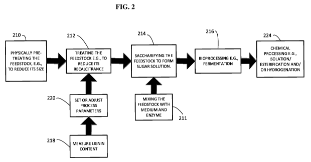
[0020] FIG. 2 is a flow diagram showing processes for manufacturing sugar
solutions
from a feedstock.
[0021] FIG. 3 is a flow diagram showing processes for manufacturing sugar
solutions
from a feedstock showing a second fermentation.
CA 02886459 2015-03-26
WO 2014/138594
PCT/US2014/021796
[0022] FIG. 4 is a diagram illustrating a reaction scheme for converting a
sugar to an
alcohol with ethyl butyrate as the ester.
DETAILED DESCRIPTION
[0023] Using the methods and systems described herein, cellulosic and
lignocellulosic
feedstock materials, for example that can be sourced from biomass (e.g., plant
biomass,
animal biomass, paper, and municipal waste biomass) and that are often readily
available but
difficult to process, can be turned into useful products. Included are methods
and systems to
produce useful primary products, for example, alcohols, acids, and sugars. The
invention also
relates to methods and systems to convert these primary products to useful
secondary
products, for example, esters and alcohols (e.g., butanol, ethanol, esters and
mixtures of
these).
[0024] Enzymes and biomass-destroying organisms that break down biomass,
such as the
cellulose, hemicellulose and/or the lignin portions of the biomass, contain or
manufacture
various cellulolytic enzymes (cellulases), ligninases, xylanases,
hemicellulases or various
small molecule biomass-destroying metabolites. FIG. 1 provides some examples
of these
biomass-destroying processes. A cellulosic substrate is initially hydrolyzed
by
endoglucanases at random locations producing oligomeric intermediates. These
intermediates are then substrates for exo-splitting glucanases such as
cellobiohydrolase to
produce cellobiose from the ends of the cellulose polymer. Cellobiose is a
water-soluble 1,4-
linked dimer of glucose. Finally cellobiase cleaves cellobiose to yield
glucose. In the case of
hemicellulose, a xylanase (e.g., hemicellulase) acts on this biopolymer and
releases Xylo-
oligosaccharides and xylose as possible products.
[0025] FIG. 2 shows processes for manufacturing sugars and fermentation
products from
a feedstock (e.g., cellulosic or lignocellulosic materials). In an initial
step (210) the method
includes, optionally, mechanically treating a cellulosic and/or
lignocellulosic feedstock.
Before and/or after this treatment, the feedstock can be treated with another
physical
treatment (212), for example irradiation, sonication, steam explosion,
oxidation, pyrolysis or
combinations of these, to reduce or further reduce its recalcitrance. A sugar
solution e.g.,
including glucose, xylose and combinations of these, is formed by
saccharifying the
feedstock (214). The saccharification can be, for example, accomplished
efficiently by the
addition of one or more enzymes, e.g., cellulases and xylanases (211) or one
or more
enzymes and one or more acids in any order. The sugar solution can be
bioprocessed (216),
6
CA 02886459 2015-03-26
WO 2014/138594
PCT/US2014/021796
for example by utilizing an organism to ferment the sugars to a primary
product, e.g., an
alcohol, a carboxylic acid, a ketone, hydrogen and combinations of these.
Optionally, the
fermentation can include more than one organism and comprises more than one
fermentation
step, for example producing one or more product simultaneously or
sequentially. Optionally,
the fermentation can be selective to one sugar. The primary product of the
bioprocessing step
can be chemically processed (224). For example, a carboxylic acid can be
hydrogenated to an
alcohol, esterified and/or esterified and then hydrogenated. Hydrogenation can
occur in a
batch reactor, or, in a continuous reactor. Optionally, the chemically
processing can include
isolation of the product, for example by a column extraction, solvent
extraction and/or by
distillation. If desired, the steps of measuring lignin content (218) and
setting or adjusting
process parameters based on this measurement (220) can be performed at various
stages of
the process, for example, as described in U.S. Application Number 12/704,519,
filed on
February 11, 2011, the complete disclosure of which is incorporated herein by
reference.
[0026] In an analogous embodiment. Fig. 3 which is similar to Fig. 2, but
with a different
naming scheme. After saccharification the mixture is fermented at step 217
such that only
one of the sugars is fermented to form a first product within a mixture of at
least a second
(unfermented) sugar, and fermentation solids. The first product at step 225 is
isolated by any
of the isolation means described herein. Optionally, the fermentation solids
may be separated
from at least the second (unfermented) sugar at step 232. A second
fermentation process at
step 227 will convert the second sugar to a second product which can be
isolated by any of
the isolation means described herein at step 230. Examples of the first and
second sugar can
be glucose and xylose, respectively, with the glucose being converted in the
first fermentation
step. For example, depending on the fermentation organism and/or fermentation
conditions
the glucose can be converted to ethanol or lactic acid. Alternately, the first
sugar can be
xylose and the second sugar can be glucose. In this case, the xylose
fermentation product is
the first product.
[0027] FIG. 4 shows an example of a reaction scheme for converting a sugar
to an
alcohol, specifically butanol. In a first step, for example, xylose is
fermented to n-butyric
acid. It should be understood that the iso-butyric acid may also undergo a
similar reaction
scheme. In a second step the butyric acid is contacted with the quaternary
amine
functionalized resin AmberliteTM 400. Butyrate becomes associated with the
quaternary
amine groups and is extracted from solution in this second step. In a third
step the resin and
bound butyrate is contacted with a strong acid, e.g., aqueous sulfuric acid,
with the effect of
protonating the butyrate and forming free butyric acid. The butyric acid can
then be extracted
7
CA 02886459 2015-03-26
WO 2014/138594
PCT/US2014/021796
by ethanol or other alcohol providing butyric acid in an alcoholic solution.
In a fourth step the
butyric acid and ethanol (optionally additional ethanol can be added) is
contacted with an
optionally catalyst and heated (e.g., to refluxing temperatures around 80 to
90 C at
atmospheric pressure) so that an esterification reaction occurs producing
ethyl butyrate. In a
fifth step, the ethyl butyrate is hydrogenated to butanol and ethanol
utilizing hydrogen and a
catalyst (e.g., Re/A1203). The hydrogenation step can be carried out in any
reactor suited for
hydrogenations.
[0028] The fermentation can produce a carboxylic acid, for example, as
described in US
APPN 13/177827 filed on July 7, 2011 and US APPN 13/668358 filed on November
5, 2012,
the entire disclosure of which are incorporated herein by reference. The
carboxylic acid can
be, for example any carboxylic acid with between 1 to 20 carbons and 1 to 5
carboxylic acid
(-CO2H) groups (e.g., 1 to 10 carbons and 1 to 4 carboxylic acid groups, 1 to
5 carbons and 1
to 3 carboxylic acid groups). For example some carboxylic acids that can be
utilized in the
methods described herein are acetic acid, propionic acid, tartaric acid,
malonic acid, succinic
acid, glutaric acid, adipic acid, benzoic acid, phthalic acid, maleic acid,
gluconic acid,
traumatic acid, muconic acid, butyric acid (e.g., n-butyric acid, isobutyric
acid), valeric acid,
caproic acid, lauric acid, palmitic acid, stearic acid and arachidic acid.
[0029] Sugars from biomass can include one or more sugars. For example,
some
fermenting species can consume more than one sugar simultaneously or
sequentially. Some
fermenting species prefer one sugar. For example, some organisms may prefer
the
fermentation of fructose as described in PCT application No. PCT/U512/71097
filed Dec 20,
2012, designating the US and published in English. Optionally, the sugar
solution can be
processed prior to any fermentation step. For example, a saccharified solution
as prepared by
the methods described herein can be purified and/or processed by filtration
(e.g., including
rotary vacuum drum filtration), chromatography (e.g., simulated moving bed
chromatography), electrodialysis including bipolar electrodialysis,
crystallization and
combinations of these. Optionally, processing can include fermenting one sugar
in a mixture
of two sugars and removal of the fermentation product, leaving a sugar
solution of
substantially the second sugar which can be more easily utilized, for example
isolated and/or
fermented (e.g. to a carboxylic acid). Some exemplary methods for purification
and/or
processing that can be utilized are discussed in co-pending U. S. Provisional
Application
Serial No's. 61/774,775, 61/774,780 and 61/774,761, the disclosures of which
are
incorporated herein by reference. In some cases, a biomass source can provide
a higher
amount of essentially only one sugar, for example some paper products, cotton
and other
8
CA 02886459 2015-03-26
WO 2014/138594
PCT/US2014/021796
biomass that is almost entirely a glucose source with little if any xylose.
Other biomass
sources may provide mostly xylose and/or lignin.
[0030] Some suitable microorganisms to produce butyrate can include C.
saccharobutylacetonicum, C. saccharoperbutylacetonicum, C. saccharobutylicum,
C.
Puniceum, C. beijemckn, C. acetobutylicum, C. acetobutylicum, C. roseum, C.
aurantibutyricum, C. felsineum and C. tyrobutyricum. It can be beneficial to
supply additives
during fermentation, for example acids, bases, buffers, amino acids, vitamins,
blackstrap
molasses, reinforced clostridia media (RCM), metal ions, yeast extract,
distillate bottoms,
meat extracts, vegetable extracts, peptones, carbon sources and proteins. For
example the
addition of metal ions of Fe, Mn, Mg, Na, Cu, Zn and combinations of these can
be
beneficial. Other additives, for example, p-aminobenzoic acids, choline,
inositol, thiamin, and
albumin can be beneficial.
[0031] A preferred additive that can be utilized is the distillate bottom
from a fermented
saccharified lignocellulosic or cellulosic material (e.g., biomass). For
example the yeast
fermentation of a saccharified material as described herein producing ethanol
can be distilled
to produce a distillation bottom. The distillate bottom containing yeast cells
and spent
biomass (e.g., lignin, non-fermented sugars, proteins) can be used as an
additive to a second
fermentation. The distillate bottom can be optionally purified prior to use,
for example, by
methods described herein (e.g., rotary vacuum drum filters, simulated moving
bed
chromatography and improvements to simulated moving bed chromatography,
filtration,
precipitation). The concentration of solids (e.g., dissolved and/or suspended
solids) can be at
least about 5 wt.% (e.g., at least about 10 wt.%, at least about 20 wt.%, at
least about 20
wt.%, at least about 30 wt.%, at least about 40 wt.%, at least about 50 wt.%,
at least about 60
wt.%, between about 10 and 90 wt.%, between about 20 and 60 wt.%). The
distillate bottom
be used directly in the distillation or it can be diluted with a solvent
(e.g., water) and used as
at least 5 wt.% distillate bottom to solvent (e.g., at least 10 wt.%, at least
20 wt.%, at least 30
wt.%, at least 40 wt.%, between about 10 and 80 wt.%, between about 10 and 60
wt.%,
between about 10 and 50 wt.%, between about 20 and 50 wt.%, between about 20
and 40
wt. %). The distillation bottom additive can be used in combination with other
additive as
herein described and additional sugars (e.g., glucose and/or xylose).
[0032] During fermentation, the pH of the fermentation media can be an
important
parameter to control. Buffers, for example, phosphate, sulfate and acetate
buffers can help
maintain a target pH. Addition of acids and bases (e. g., ammonium hydroxide,
sodium and
potassium hydroxides, acetic acid, sulfuric acid, phosphoric acid, nitric
acids) can also be
9
CA 02886459 2015-03-26
WO 2014/138594
PCT/US2014/021796
added before, after and during the fermentation to maintain and or change or
control the pH.
During fermentation, the pH is optimally between about 2 and 8 (e.g., between
about 3 and 8,
between about 4 and 8, between about 4 and 7). Maintaining the pH above a
critical value, for
example above about 3 (e.g., above about 3.5, above about 4) by the addition
of a base can
often improve the fermentation. This control can be particularly important
while using
acidogenic bacteria since the acid products can lower the pH during the
fermentation to
values that are toxic to the organisms.
[0033] The temperature can also be a controlling and important parameter
during
fermentation. Optimally the temperature is maintained between about 20 and 50
C (e.g.,
between about 20 and 40 C, between about 30 and 40 C). In some instances
lower or higher
temperatures from an optimal temperature can be utilized to induce a desired
fermentation
phase, e.g., acidogenisis, solventogenisis, log growth, sporulation.
[0034] For anaerobic organisms it is preferable to conduct the fermentation
in the absence
of oxygen e.g., under a blanket of an inert gas such as N2, Ar, He, CO2 or
mixtures thereof.
Additionally, the mixture may have a constant purge of an inert gas flowing
through the tank
or bioreactor during part of or all of the fermentation.
[0035] The fermenting or saccharifying organism can be immobilized on a
support. For
example an application of this process is described in U.S. Patent 5,563,069.
The organism
can be supported on a cellulosic or lignocellulosic material as describe in
U.S Patent serial
No 12/782,543 the entire disclosure of which is herein incorporated by
reference.
[0036] The product of fermentation can be removed from the fermentation
media by any
useful means. For example, butyric acid and other fermentation products can be
removed/purified by adding base to the fermentation solution, adding acid to
the fermented
solution, extraction, filtration, centrifugation, distillation, cross flow
filtration, membrane
filtration, pertraction, electrodialysis, adsorption and/or bonding to a resin
or other solid, and
combinations of these methods. Optionally, after purification, if the product
is wet, the
product can be dried, for example by contacting the product with molecular
sieves or other
drying agents (e.g., sodium sulfate, magnesium sulfate). An extraction method
for organic
acids including formation of an alkyl amine adduct in an aqueous solution that
can be
subsequently extracted from the aqueous phase is described in US Application
Serial No.
12935075 filed March 27, 2009, the entire disclosure of which is incorporated
herein by
reference. In one preferred embodiment, organic acids (e.g., butyric acid) can
be extracted by
adsorption/adduct formation/bonding to on a solid support, for example a
resin, solid and/or
polymer support.
CA 02886459 2015-03-26
WO 2014/138594
PCT/US2014/021796
[0037] In some embodiments the fermented product can be extracted directly
from the
fermentation solution or from a solution that has been distilled. The
extracting solvent can be,
for example, an alcohol, an ether, an oil (e.g., castor oil, coconut oil, palm
oil). For example,
for the extraction of carboxylic acid (e.g., butyric acid) some particularly
useful alcohols are
fatty alcohols, for example, having between 6 and 20 carbons and 1 to 5
alcoholic functional
groups (e.g., n-hexanol, n-octanol, n-decanol, n-dodecanol, lauryl alcohol,
myristyl alcohol,
cetyl alcohol, stearyl alcohol, oleyl alcohol, linoleyl alcohol, isomers of
these and
combinations of these). The acid can be protonated by treating the solution
containing the
acid with a mineral acid to adjust the pH to about pH 3 (e.g., between about
pH 2 and 4) prior
to extraction.
[0038] The acid can be esterified as discussed herein to the ester. The
alcohols listed
herein can be also utilized to esterify the fermentation derived acid. The
esterification can be
done in the extraction solution. For example, an alcohol can be added to the
extracting
solvent. If the extracting solvent is an alcohol then the alcohol can be
directly utilized for
esterification with or without concentration or dilution of the alcohol. For
example, butyric
acid derived from the fermentation of a biomass can be protonated by the
addition of sulfuric
acid to the fermented solution. The butyric acid can be subsequently distilled
away from the
acidified solution. The distillate can then be extracted in an alcohol (e.g.,
n-octanol). An acid
catalyst can be added to the extracted acid and alcohol and the solution
heated to produce an
ester. Alternatively, fermented solution can be acidified and then directly
extracted with an
alcohol (e.g., octanol). The mixture can then be esterified.
[0039] In some embodiments the resins utilized to adsorb organic acids
(e.g., butyric
acid) can be polymers with ion exchange properties, for example having
quaternary amine
functional groups that can ion exchange with the acidic proton of the acid.
For example
AmberliteTM IRA 410, AmberliteTM IRA-67, AmberliteTM 96, AmberliteTM XAD-
1180M,
AmberliteTM XAD-2, AmberliteTM 400 and AmberliteTM IRN150. A solution
containing the
organic acid can be contacted with the ion exchange resin by passing the
solution through a
packed column (e.g., glass, metal, plastic) of the resin. Optionally, the
solution containing the
organic acid can be combined with the resin in a vessel (e.g., in a batch
mode) and agitated
(e.g., shaken, stirred) for several minutes to several hours (e.g., 1 mm to 24
hours, 1 min to 12
hours, 1 mm to 8 hours, 1 mm to 4 hours, 1 mm to 1 hour, 1 hour to 4 hours, 1
hour to 12
hours). In batch mode the organic acid depleted solution can be decanted or
filtered from the
resin after a sufficient time to adsorb/bond at least some of the organic
acid. The amount of
11
CA 02886459 2015-03-26
WO 2014/138594
PCT/US2014/021796
butyric acid in the batch separation or column separation methods can be
monitored by any
useful method, for example, head space analysis, titrations and HPLC.
[0040] A resin for adsorbing an organic acid can be contacted with the
fermenting
solution while the fermentation is still processing or after the fermentation
is complete. For
example the active fermentation media can be pumped through a column of the
resin or the
resin can be added to the fermentation broth.
[0041] The organic acid can, for example, be removed from the resin by
contacting the
resin and bound organic acid with an acid solution. For example the acid
solution can include
a mineral acid (e.g., hydrochloric, sulfuric, phosphoric, nitric) or the acid
can be an organic
acid (acetic acid, trifluoroacetic acid). It is generally preferable to use an
acid with a low pKa,
e.g., about lower than the pKa of butyric acid e.g., a pKa of less than about
4, less than about
3, less than about 2. The pH of the solution after acidification is optimally
between about 1
and 6 (e.g., between about 2 and 5, between about 2 and 4). It can be
advantageous to utilize
a solvent with or without water to aid in extracting the organic acid or
organic acid salt from
the resin. For example the solvent can be an alcohol (e.g., methanol, ethanol,
propanol,
butanol or the fatty acid alcohols previously described), an ether (e.g.,
diethyl ether,
tetrahydrofuran, methyl tert-butyl ether, di-isopropyl ether), acetonitrile,
acetone, butyl
acetate, dimethylformamide, ethyl acetate and combinations of these. These can
be combined
in any percentage with water and each other. A preferred method of removing
adsorbed
organic acid from a resin packed column is elution with acidified alcohol
(e.g. ethanol and/or
methanol with and added acid) or an acidified alcohol/water solution (e.g.,
ethanol/water,
methanol/water with and added acid). Resins can be recycled after removal of
the acid, for
example by flushing with excess of the acidified solution followed by flushing
with water,
optionally deionized water.
[0042] The acidified eluent/extracting solution from the resin processing
containing the
carboxylic acid can be neutralized by addition of a base. This can produce the
salt of the
carboxylic acid. The salts of the carboxylic acid can be evaporated to dryness
and then oven
dried (e.g. at 80 to 100 C). The salts can be subsequently utilized in
esterification reactions,
with optionally re-acidification prior to the reaction.
[0043] In an alternative to acidification to remove the organic acid from
the resin, the
acidic proton of the organic acid can be removed by ion exchange with a cation
to form the
salt of an organic acid. Some useful exchanging ions include, for example,
quaternary
ammonium ions, alkali metal ions and alkali earth metal ions, transition metal
ion and
12
CA 02886459 2015-03-26
WO 2014/138594
PCT/US2014/021796
combinations of these. The salt of the carboxylic acid thus produced can be
further processed
as previously discussed.
[0044] The formation of esters as discussed herein from carboxylic acids
can be done by
utilizing any alcohol, for example, alcohols containing 1 to 20 carbon atoms
and 1 to 5
alcohol groups (e.g., 1 to 10 carbon atoms and 1-4 alcohol groups, 1 to 10
carbon atoms and
1-2 alcohol groups). Some exemplary alcohols are methanol, ethanol, propanol,
n-butanol, n-
hexanol, n-octanol, n-decanol, n-dodecanol, lauryl alcohol, myristyl alcohol,
cetyl alcohol,
stearyl alcohol, oleyl alcohol, linoleyl alcohol, diols (e.g., ethylene
glycol), triols (e.g.,
glycerol), polyols, isomers of these and combinations of these. Esterification
can be done
with an excess of the alcohol, for example in a molar ratio of between about 1
to 50, with or
without a diluting solvent. The esterification reaction can be carried out at
temperatures
between about 80 and 300 C (e.g., between about 80 and 200 C, between
about 80 and
150 C) and under pressures of between about 1 to 30 atm. (e.g.. between
about 1 and 20
atm., between about 1 and 10 atm.). In some implementations the alcohol that
is utilized
includes alcohol that is derived from the fermentation of saccharified
lignocellulosic or
cellulosic feeds, for example, as described herein, ethanol and or butanol can
be utilized. The
alcohol can also be derived from other renewable sugar sources and methods,
for example the
sources can include, starch and sugars from corn kernels, sugar cane, fruits,
legumes and/or
beets. Ethanol and butanol are particularly useful alcohols that can be
generated by the
method described herein. The alcohol may also be obtained from hydrocarbon
sources.
[0045] The esterification reaction is facilitated by utilizing a catalyst,
e.g., an acid
catalyst. The acid catalyst can be homogeneous or heterogeneous. Some useful
homogeneous
acid catalysts include sulfuric, phosphoric, nitric, hydrochloric and
trifluoroacetic acid.
Heterogeneous acid catalysts include resins or functionalized polymers, for
example,
sulfonated polystyrene resins. The acids can be solid catalysts e.g., as
zeolites, sulfonated
carbons, alumina, clays, aluminosilicates, heteropolyacids, silica and
combinations of these.
Dehydrating agents, e.g., molecular sieves can be used in addition to the
catalysts or after the
esterification to remove water formed during the esterification. Other
methods, for example
distillation as a low-boiling azeotrope with toluene can be used to remove
water.
[0046] In some embodiments an acid (e.g., butyric acid) can be esterified
while it is
bound to a resins utilized to adsorb organic acids. The ester can then be
extracted into a
solvent, for example, the solvents previously discussed for removing the
protonated acid from
a resin.
13
CA 02886459 2015-03-26
WO 2014/138594
PCT/US2014/021796
[0047] In some optional embodiments esters can be prepared utilizing an
organism. For
example Staphylococci can be combined with carboxylic acids (e.g., butyric
acid) and
alcohols (e.g., ethyl alcohol) to produce ethyl butyrate. Other carboxylic
acids, alcohols and
organism combinations can also be utilized. Other esters that can be formed
from acids and
alcohols derived from sugars by organisms (e.g., S. cerevisiae) include
isoamyl acetate, ethyl
caproate, ethyl caprylate, ethyl caproate, phenylethyl acetate, ethyl laurate,
ethyl myristate,
and ethyl palmitate.
[0048] The ester can be separated from excess alcohol, unreacted acid and
impurities by
any useful method. For example distillation, chromatography, filtration can be
useful. If there
is any excess acid it can also be removed by passing over/through ion exchange
material, for
example as previously described. The ester can also be simply utilized as a
mixture, mostly of
excess alcohol, for example as a direct fuel or fuel additive, e.g.,
distributed to reformulators,
for high octane fuel and/or fuel additive. Other uses as a mixture to the
chemical, food,
flavor, fragrances and pharmaceutical industries are evident to those skilled
in the art.
[0049] The organic acids produced by the methods herein described can be
hydrogenated
directly to an alcohol. However, direct hydrogenation requires very high
pressures and the
catalysts are often quickly deactivated. The esterification is advantageous in
allowing more
mild conditions to be utilized for a hydrogenolysis. For example direct
hydrogenation can
require pressures in excess of 100 atm., temperatures above 300 C and
catalysts lifetimes of
only a few hours before the catalysts need to be regenerated or replaced. The
hydrogenolysis
of esters can be done at temperatures between about 100 to 300 C (e.g., 120
to 250 C, 150
to 300 C), hydrogen pressures less than about 120 atm. (e.g., between about
5 and 120 atm.,
between about 5 and 60 atm.) and catalysts can last for at least an hour
(e.g., at least two
hours, at least 5 hours, at least 8 hours, at least 16 hours, more than a day,
two days, a week, a
month, a year) before needing to be regenerated and/or replaced.
[0050] Important parameters to consider during the hydrogenolysis of the
ester are the
conversion and selectivity to the products. The conversion can be expressed as
a percentage
of the product reacted (e.g., initial product/final product times 100%). The
conversion can
also be expressed as the rate of consumption of the staring material (e.g.,
the ester). The
selectivity is a measure of the amount of the desired product that is
obtained, in comparison
to unwanted products (e.g., side products, decomposition products). The
selectivity can be
expressed as a percentage, for example a percent purity, or as a rate of
formation of a desired
product vs. the rate of formation of undesired products (or the rate of
formation of desired
product to the rate of consumption of the starting material). Some unwanted
products can be
14
CA 02886459 2015-03-26
WO 2014/138594
PCT/US2014/021796
partial reduction products, oligomers and/or thermal decomposition products.
Although not
always the case, it is often found that there is an inverse relation between
the conversion rates
and selectivity, so that it can be difficult to drive the reaction quickly to
completion with a
high selectivity.
[0051] Catalysts are utilized during the hydrogenolysis. Catalysts can
include the metals
Pd, Pt, Os, Ru, Rb, Re, Ir, Rh, Ni, Co, Mo, W, Cu, Zn, Cr, oxides of these and
combinations
of these. In some cases promoter or moderators species are added/combined
including Cr,
Mn, Pb, Zn, Cd, Ag, Ba, Ca, Mg, Sn, Ni, Co, U, As and Ge oxides of these and
combinations
of these. One or more catalyst and one or more promoter can be combined in any
concentration and ratio. The promoters increase the performance of the
catalyst, for example
increasing the conversion and selectivity.
[0052] The catalysts and promoters can be used as bulk catalysts (e.g., not
on a support).
Bulk catalysts can be formed into shapes to increase surface area and allow
flow of reactants
over its surface. For example in the form of: wool, a mesh, a grid, a wire, a
perforated solid
with channels, a sponge, beads and/or a powder. The catalysts and promoters
can be mixed
when utilized in bulk, for example powers of one or more catalyst and powders
of one or
more promoters can be combined/mixed. The metals or metal with promoter
species can be
advantageously adsorbed and or bonded onto a support. The support can be, for
example,
alumina, silica, aluminosilicates, clays, zeolites (e.g., USY and beta
zeolite) or other
inorganic materials. The supported catalysts typically have between about 0.1
wt. % and 10
wt. % of each metal (e.g., between 0.1 and 1 wt. %), although higher amounts
can be used.
One or more metal and one or more promoter can be combined with one or more
support in
all combinations. These supported catalyst may be formed into any convenient
form.
[0053] The catalysts can be homogeneous catalysts, for example
tris(triphenylphosphine)rhodium(I) chloride, and similar catalysts wherein the
metal is
complexed with stabilizing ligand(s) (e.g., amines, phosphines, alcohols,
ethers, ketones,
carboxylates, acetylacetonates, optionally bis, tri or tetrakis chelating
ligands, combinations
of these). The catalyst can be the polymer supported analog of a homogeneous
catalyst, for
example, wherein the ligands are attached to a polymer, e.g., functionalized
polystyrenes
wherein the functional groups are the ligands previously mentioned.
[0054] Supported catalysts can be prepared by any useful means, for
example, by using
the incipient wetness method, a decomposition precipitation method, a solution
self-assembly
method, and/or by vapor phase deposition/decomposition. For example, utilizing
the incipient
wetness method, a desired metal precursor can be dissolved or suspended in a
volume of
CA 02886459 2015-03-26
WO 2014/138594
PCT/US2014/021796
solvent similar to the pore volume of the support and it is combined with the
support. The
catalyst can be activated. Activation can include removal of the solvent under
vacuum,
calcination, for example in the presence of oxygen, nitrogen, hydrogen or
other gasses, in any
order and repeatedly. The catalysts can be added before the promoter, with the
promoter,
after the promoter or in combinations of addition steps. The supported
catalysts can be
formed into beads, or extruded into rods and other shapes. Often these are
combined with
binders (e.g., inert ceramic material, porous binders).
[0055] Some catalysts, conditions, equipment and systems that can be
utilized herein for
the hydrogenolysis and esterification reaction are described in: "Catalysis of
Organic
Reactions" edited John R. Sowa, Jr., CRC Press (2005); "Catalytic Naphtha
Reforming
Second Edition, Revised and Expanded" edited George J. Antos and Abdullah M.
Aitani,
Marcel Dekker (2005) chapters 6, 8 and 9; and "Steam reforming catalysts
Natural gas,
associated gas and LPG" Johnson Matthey, pages 1-15; For example bi and tri
metallic
supported catalysts of SnRu and SnRePt can be utilized for the hydrogenolysis
of ethyl
butyrate.
[0056] Catalysts can be utilized for hydrogenolysis in a batch mode. For
example the
ester is combined, often with a solvent, in a vessel (e.g., a ParrTM reactor).
The vessel can be
sparged with hydrogen and/or pressurized with hydrogen. The vessels can be
equipped with
heaters, (e.g., heating jackets) and agitators (e.g., propellers, impellers).
The catalysts can
also be utilized in a fluidized bed reactor. These require a high gas flow
rate, e.g., of an inert
gas (e.g., nitrogen, He, Ar) in addition to hydrogen and the ester. The
catalyst is fluidized by
the rapid flow of gases through the reactor. One or more catalysts can be
utilized sequentially
or in combination (e.g., mixed together). A loop reactor may be used as it is
a design option
of a batch reactor, except the liquid in the vessel is recirculated outside of
the reactor. If
utilized sequentially, the catalysts can be utilized under different reaction
conditions, e.g.,
temperatures, pressures (e.g., hydrogen pressures) and/or agitation (e.g.,
stirring rates). These
combinations can, for example, optimize throughputs and combined
conversion/selectivity.
[0057] Optionally, the catalysts are utilized in a fixed bed flow reactors
(e.g., a flow
reactor, packed bed reactor, trickle bed reactor). These reactors are
configured as a column
packed with the catalysts (e.g., bulk or supported catalyst) through which the
reactants (e.g.,
esters and hydrogen) are flowed. The columns can be heated, for example, by a
heating jacket
charged with a heating fluid (e.g., water, high pressure water, oil), steam,
electric heaters
(e.g., resistive heating), or any other heating means. The columns can also be
designed to
withstand high pressures e.g., at least about 50 psi, at least about 100 psi,
at least about 150
16
CA 02886459 2015-03-26
WO 2014/138594
PCT/US2014/021796
psi, at least about 200 psi, at least about 300 psi, at least about 500 psi.
The columns can also
be equipped with safety equipment e.g., pressure release valves, and high
temperature process
shut off (e.g., flow shut off, venting). Optionally, two or more fixed bed
reactors can be
utilized in series for one flow stream of reactants (e.g., up to 20, up to 10,
2 to 5, 3 to 10, 1 to
3). In some optional configurations some of the reactors are by-passed, for
example, to keep
them as a backup. Having available backups is particularly useful to avoid
down time when
one or more of the flow reactors are not operating within acceptable
parameters e.g., if
catalysts in the reactor are deactivated. Another advantage of utilizing
reactors in series is
that the reactors can be charged with different catalysts, for example having
different
selectivity and conversion rates, for optimal throughputs and combined
conversion/selectivity. The columns can also be run under different
conditions, e.g., flow
rates, pressures and temperatures. For example two or more columns can be
utilized wherein
the difference in temperatures can be about 0 to 10 C (e.g., about 10 to 200
C, about 50 to
200 C, about 50 to 150 C, about 50 to 100 C). In addition to or
alternatively the
difference in pressure (e.g., hydrogen pressure) when using at least more than
one column,
can be between about 0 to 5 atm. (e.g. between about 5 and 50 atm., between
about 10 and 50
atm., between about 30 and 50 atm.).
[0058] The hydrogenolysis catalysts as described can be recycled /
regenerated. For
example often the catalysts are oxidized by heating to high temperature in an
oxidizing
environment (e.g., in the presence of oxygen) e.g., between about 200 and 800
C (e.g., 400
to 600 C). After purging with an inert gas (e.g., nitrogen, argon, helium)
the catalysts are
reduced at a high temp e.g., between about 200 and 800 C. The reducing
agent, for
example, can be hydrogen gas made to flow over the catalyst.
[0059] The hydrogen that is utilized in the processes described herein can
be supplied by
biogas, for example from the anaerobic digestion of biomass, e.g., treated
biomass as
described herein. The hydrogen may be cleaned prior to its use for
hydrogenation.
Contaminants such as carbon monoxide, should be removed. Other sources of
hydrogen
include locating the hydrogenolysis reactor system close to a hydrogen source,
including a
pipeline and steam reformer of methane, natural gas or the like.
[0060] Using the catalysts, overall selectivity of greater than about 90 %
can be achieved
(e.g., greater than 95%, greater than 98%, greater than 99%) can be achieved.
The overall
conversion rates are above 80% (e.g., greater than about 90%, greater than
about 95%,
greater than about 99%).
17
CA 02886459 2015-03-26
WO 2014/138594
PCT/US2014/021796
[0061] The alcohols produced by the hydrogenolysis can be separated, for
example, by
distillation if the boiling point is different enough. For example the
hydrogenolysis product of
ethyl butyrate, ethanol and butanol, can be separated by distillation. The
ethanol that is
recovered can be re-used for esterification. The mixture of alcohols can even
be utilized
without separation, for example as a direct fuel or fuel additive. Other uses
as a mixture or
purified separated products applicable to the chemical, food, flavor,
fragrances and
pharmaceutical industries will be recognized by those skilled in the art. In
the case of some
esters, for example butyl butyrate, the hydrogenolysis product is butanol and
separation
schemes can be used to improve impurities.
RADIATION TREATMENT
[0062] The feedstock can be treated with electron bombardment to modify its
structure to
reduce its recalcitrance. Such treatment can, for example, reduce the average
molecular
weight of the feedstock, change the crystalline structure of the feedstock,
and/or increase the
surface area and/or porosity of the feedstock.
[0063] Electron bombardment via an electron beam is generally preferred,
because it
provides very high throughput. Electron beam accelerators are available, for
example, from
IBA, Belgium, and NHV Corporation, Japan.
[0064] Electron bombardment may be performed using an electron beam device
that has
a nominal energy of less than 10 MeV, e.g., less than 7 MeV, less than 5 MeV,
or less than 2
MeV, e.g., from about 0.5 to 1.5 MeV, from about 0.8 to 1.8 MeV, or from about
0.7 to 1
MeV. In some implementations the nominal energy is about 500 to 800 keV.
[0065] The electron beam may have a relatively high total beam power (the
combined
beam power of all accelerating heads, or, if multiple accelerators are used,
of all accelerators
and all heads), e.g., at least 25 kW, e.g., at least 30, 40, 50, 60, 65, 70,
80, 100, 125, or 150
kW. In some cases, the power is even as high as 500 kW, 750 kW, or even 1000
kW or
more. In some cases the electron beam has a beam power of 1200 kW or more,
e.g., 1400,
1600, 1800, or even 3000 kW.
[0066] This high total beam power is usually achieved by utilizing multiple
accelerating
heads. For example, the electron beam device may include two, four, or more
accelerating
heads. The use of multiple heads, each of which has a relatively low beam
power, prevents
excessive temperature rise in the material, thereby preventing burning of the
material, and
also increases the uniformity of the dose through the thickness of the layer
of material.
18
CA 02886459 2015-03-26
WO 2014/138594
PCT/US2014/021796
[0067] It is generally preferred that the bed of biomass material has a
relatively uniform
thickness. In some embodiments the thickness is less than about 1 inch (e.g.,
less than about
0.75 inches, less than about 0.5 inches, less than about 0.25 inches, less
than about 0.1 inches,
between about 0.1 and 1 inch, between about 0.2 and 0.3 inches).
[0068] In some implementations, it is desirable to cool the material during
and between
dosing the material with electron bombardment. For example, the material can
be cooled
while it is conveyed, for example by a screw extruder, vibratory conveyor or
other conveying
equipment. For example cooling while conveying is described in U. S.
Provisional Patent
Application Nos. 61/774,735, and 61/774,752 the entire description therein is
herein
incorporated by reference.
[0069] To reduce the energy required by the recalcitrance-reducing process,
it is desirable
to treat the material as quickly as possible. In general, it is preferred that
treatment be
performed at a dose rate of greater than about 0.25 Mrad per second, e.g.,
greater than about
0.5, 0.75, 1, 1.5, 2, 5, 7, 10, 12, 15, or even greater than about 20 Mrad per
second, e.g., about
0.25 to 2 Mrad per second. Higher dose rates allow a higher throughput for a
target (e.g., the
desired) dose. Higher dose rates generally require higher line speeds, to
avoid thermal
decomposition of the material. In one implementation, the accelerator is set
for 3 MeV, 50
mA beam current, and the line speed is 24 feet/minute, for a sample thickness
of about 20
mm (e.g., comminuted corn cob material with a bulk density of 0.5 g/cm3).
[0070] In some embodiments, electron bombardment is performed until the
material
receives a total dose of at least 0.1 Mrad, 0.25 Mrad, 1 Mrad, 5 Mrad, e.g.,
at least 10, 20, 30
or at least 40 Mrad. In some embodiments, the treatment is performed until the
material
receives a dose of from about 10 Mrad to about 50 Mrad, e.g., from about 20
Mrad to about
40 Mrad, or from about 25 Mrad to about 30 Mrad. In some implementations, a
total dose of
25 to 35 Mrad is preferred, applied ideally over a couple of seconds, e.g., at
5 Mrad/pass with
each pass being applied for about one second. Applying a dose of greater than
7 to 8
Mrad/pass can in some cases cause thermal degradation of the feedstock
material. Cooling
can be applied before, after, or during irradiation. For example, the cooling
methods, systems
and equipment as described in the following applications can be utilized: US
Provisional
Application No. 61/774,735, and US Provisional Application No. 61/774,754, the
entire
disclosures of which are herein incorporated by reference.
[0071] Using multiple heads as discussed above, the material can be treated
in multiple
passes, for example, two passes at 10 to 20 Mrad/pass, e.g., 12 to 18
Mrad/pass, separated by
a few seconds of cool-down, or three passes of 7 to 12 Mrad/pass, e.g., 5 to
20 Mrad/pass, 10
19
CA 02886459 2015-03-26
WO 2014/138594
PCT/US2014/021796
to 40 Mrad/pass, 9 to 11 Mrad/pass. As discussed herein, treating the material
with several
relatively low doses, rather than one high dose, tends to prevent overheating
of the material
and also increases dose uniformity through the thickness of the material. In
some
implementations, the material is stirred or otherwise mixed during or after
each pass and then
smoothed into a uniform layer again before the next pass, to further enhance
treatment
uniformity.
[0072] In some embodiments, electrons are accelerated to, for example, a
speed of greater
than 75 percent of the speed of light, e.g., greater than 85, 90, 95, or 99
percent of the speed
of light.
[0073] In some embodiments, any processing described herein occurs on
lignocellulosic
material that remains dry as acquired or that has been dried, e.g., using heat
and/or reduced
pressure. For example, in some embodiments, the cellulosic and/or
lignocellulosic material
has less than about 25 wt. % retained water, measured at 25 C and at fifty
percent relative
humidity (e.g., less than about 20 wt.%, less than about 15 wt.%, less than
about 14 wt.%,
less than about 13 wt.%, less than about 12 wt.%, less than about 10 wt.%,
less than about 9
wt.%, less than about 8 wt.%, less than about 7 wt.%, less than about 6 wt.%,
less than about
wt.%, less than about 4 wt.%, less than about 3 wt.%, less than about 2 wt.%,
less than
about 1 wt.%, less than about 0.5 wt.%, less than about 15 wt.%.
[0074] In some embodiments, two or more electron sources are used, such as
two or more
ionizing sources. For example, samples can be treated, in any order, with a
beam of
electrons, followed by gamma radiation and UV light having wavelengths from
about 100 nm
to about 280 nm. In some embodiments, samples are treated with three ionizing
radiation
sources, such as a beam of electrons, gamma radiation, and energetic UV light.
The biomass
is conveyed through the treatment zone where it can be bombarded with
electrons.
[0075] It may be advantageous to repeat the treatment to more thoroughly
reduce the
recalcitrance of the biomass and/or further modify the biomass. In particular
the process
parameters can be adjusted after a first (e.g., second, third, fourth or more)
pass depending on
the recalcitrance of the material. In some embodiments, a conveyor can be used
which
includes a circular system where the biomass is conveyed multiple times
through the various
processes described above. In some other embodiments multiple treatment
devices (e.g.,
electron beam generators) are used to treat the biomass multiple (e.g., 2, 3,
4 or more) times.
In yet other embodiments, a single electron beam generator may be the source
of multiple
beams (e.g., 2, 3, 4 or more beams) that can be used for treatment of the
biomass.
CA 02886459 2015-03-26
WO 2014/138594
PCT/US2014/021796
[0076] The conveyors (e.g., vibratory conveyor) can be made of corrosion
resistant
materials. The conveyors can utilize structural materials that include
stainless steel (e.g., 304,
316 stainless steel, HASTELLOY ALLOYS and INCONEL Alloys). For example,
HASTELLOY Corrosion-Resistant alloys from Hynes (Kokomo, Indiana, USA) such
as
HASTELLOY B-3 ALLOY, HASTELLOY HYBRID-BC1 ALLOY,
HASTELLOY C-4 ALLOY, HASTELLOY C-22 ALLOY, HASTELLOY C-22115
ALLOY, HASTELLOY C-276 ALLOY, HASTELLOY C-2000 ALLOY,
HASTELLOY G-30 ALLOY, HASTELLOY G-35 ALLOY, HASTELLOY N
ALLOY and HASTELLOY ULTIMET alloy.
[0077] The vibratory conveyors can include non-stick release coatings, for
example
TEFLONTm (DuPont, Delaware, USA). The vibratory conveyors can also include
corrosion
resistant coatings. For example coatings that can be supplied from Metal
Coatings Corp
(Houston, Texas, USA) and others such as Fluoropolymer, XYLAN , Molybdenum
Disulfide, Epoxy Phenolic, Phosphate- ferrous metal coating, Polyurethane-
high gloss
topcoat for epoxy, inorganic zinc, Poly Tetrafluoroethylene, PPS/RYTON ,
fluorinated
ethylene propylene, PVDF/DYKOR , ECTFE/HALAR and Ceramic Epoxy Coating. The
coatings can improve resistance to process gases (e.g., ozone), chemical
corrosion, pitting
corrosion, galling corrosion and oxidation.
[0078] The effectiveness in changing the molecular/supermolecular structure
and/or
reducing the recalcitrance of the carbohydrate-containing biomass depends on
the electron
energy used and the dose applied, while exposure time depends on the power and
dose.
Optionally, the dose rate and total dose are adjusted so as not to destroy
(e.g., char or burn)
the biomass material. For example, the carbohydrates should not be damaged in
the
processing so that they can be released from the biomass intact, e.g. as
monomeric sugars.
[0079] In some embodiments, the treatment (with any electron source or a
combination of
sources) is performed until the material receives a dose of at least about
0.05 Mrad, e.g., at
least about 0.1, 0.25, 0.5, 0.75, 1.0, 2.5, 5.0, 7.5, 10.0, 15, 20, 25, 30,
40, 50, 60, 70, 80, 90,
100, 125, 150, 175, or 200 Mrad. In some embodiments, the treatment is
performed until the
material receives a dose of between 0.1-100 Mrad, 1-200, 5-200, 10-200, 5-150,
50-150
Mrad, 5-100, 5-50, 5-40, 10-50, 10-75, 15-50, 20-35 Mrad.
RADIATION OPAQUE MATERIALS
[0080] The invention can include processing the material in a vault and/or
bunker that is
constructed using radiation opaque materials. In some implementations, the
radiation opaque
21
CA 02886459 2015-03-26
WO 2014/138594
PCT/US2014/021796
materials are selected to be capable of shielding the components from X-rays
with high
energy (short wavelength), which can penetrate many materials. One important
factor in
designing a radiation shielding enclosure is the attenuation length of the
materials used,
which will determine the required thickness for a particular material, blend
of materials, or
layered structure. The attenuation length is the penetration distance at which
the radiation is
reduced to approximately 1/e (e = Euler' s number) times that of the incident
radiation.
Although virtually all materials are radiation opaque if thick enough,
materials containing a
high compositional percentage (e.g., density) of elements that have a high Z
value (atomic
number) have a shorter radiation attenuation length and thus if such materials
are used a
thinner, lighter shielding can be provided. Examples of high Z value materials
that are used
in radiation shielding are tantalum and lead. Another important parameter in
radiation
shielding is the halving distance, which is the thickness of a particular
material that will
reduce gamma ray intensity by 50%. As an example for X-ray radiation with an
energy of
0.1 MeV the halving thickness is about 15.1 mm for concrete and about 0.2.7 mm
for lead,
while with an X-ray energy of 1 MeV the halving thickness for concrete is
about 44.45 mm
and for lead is about 7.9 mm. Radiation opaque materials can be materials that
are thick or
thin so long as they can reduce the radiation that passes through to the other
side. Thus, if it
is desired that a particular enclosure have a low wall thickness, e.g., for
light weight or due to
size constraints, the material chosen should have a sufficient Z value and/or
attenuation
length so that its halving length is less than or equal to the desired wall
thickness of the
enclosure.
[0081] In some cases, the radiation opaque material may be a layered
material, for
example having a layer of a higher Z value material, to provide good
shielding, and a layer of
a lower Z value material to provide other properties (e.g., structural
integrity, impact
resistance, etc.). In some cases, the layered material may be a "graded-Z"
laminate, e.g.,
including a laminate in which the layers provide a gradient from high-Z
through successively
lower-Z elements. In some cases the radiation opaque materials can be
interlocking blocks,
for example, lead and/or concrete blocks can be supplied by NELCO Worldwide
(Burlington,
MA), and reconfigurable vaults can be utilized as described in US Provisional
Application
No.61/774,744.
[0082] A radiation opaque material can reduce the radiation passing through
a structure
(e.g., a wall, door, ceiling, enclosure, a series of these or combinations of
these) formed of the
material by about at least about 10 %, (e.g., at least about 20%, at least
about 30%, at least
about 40%, at least about 50%, at least about 60%, at least about 70%, at
least about 80%, at
22
CA 02886459 2015-03-26
WO 2014/138594
PCT/US2014/021796
least about 90%, at least about 95%, at least about 96%, at least about 97%,
at least about
98%, at least about 99%, at least about 99.9%, at least about 99.99%, at least
about 99.999%)
as compared to the incident radiation. Therefore, an enclosure made of a
radiation opaque
material can reduce the exposure of equipment/system/components by the same
amount.
Radiation opaque materials can include stainless steel, metals with Z values
above 25 (e.g.,
lead, iron), concrete, dirt, sand and combinations thereof. Radiation opaque
materials can
include a barrier in the direction of the incident radiation of at least about
1 mm (e.g., 5 mm,
mm, 5 cm, 10 cm, 100 cm, 1 m, 10 m).
RADIATION SOURCES
[0083] The type of radiation determines the kinds of radiation sources used
as well as the
radiation devices and associated equipment. The methods, systems and equipment
described
herein, for example for treating materials with radiation, can utilized
sources as described
herein as well as any other useful source.
[0084] Sources of gamma rays include radioactive nuclei, such as isotopes
of cobalt,
calcium, technetium, chromium, gallium, indium, iodine, iron, krypton,
samarium, selenium,
sodium, thallium, and xenon.
[0085] Sources of X-rays include electron beam collision with metal
targets, such as
tungsten or molybdenum or alloys, or compact light sources, such as those
produced
commercially by Lyncean.
[0086] Alpha particles are identical to the nucleus of a helium atom and
are produced by
the alpha decay of various radioactive nuclei, such as isotopes of bismuth,
polonium, astatine,
radon, francium, radium, several actinides, such as actinium, thorium,
uranium, neptunium,
curium, californium, americium, and plutonium.
[0087] Sources for ultraviolet radiation include deuterium or cadmium
lamps.
[0088] Sources for infrared radiation include sapphire, zinc, or selenide
window ceramic
lamps.
[0089] Sources for microwaves include klystrons, Slevin type RF sources, or
atom beam
sources that employ hydrogen, oxygen, or nitrogen gases.
[0090] Accelerators used to accelerate the particles (e.g., electrons or
ions) can be DC
(e.g., electrostatic DC or electrodynamic DC), RF linear, magnetic induction
linear or
continuous wave. For example, various irradiating devices may be used in the
methods
disclosed herein, including field ionization sources, electrostatic ion
separators, field
ionization generators, thermionic emission sources, microwave discharge ion
sources,
23
CA 02886459 2015-03-26
WO 2014/138594
PCT/US2014/021796
recirculating or static accelerators, dynamic linear accelerators, van de
Graaff accelerators,
Cockroft Walton accelerators (e.g., PELLETRON accelerators), LINACS,
Dynamitrons
(e.g., DYNAMITRON accelerators), cyclotrons, synchrotrons, betatrons,
transformer-type
accelerators, microtrons, plasma generators, cascade accelerators, and folded
tandem
accelerators. For example, cyclotron type accelerators are available from IBA,
Belgium, such
as the RHODOTRONTm system, while DC type accelerators are available from RDI,
now
IBA Industrial, such as the DYNAMITRON . Other suitable accelerator systems
include, for
example: DC insulated core transformer (ICT) type systems, available from
Nissin High
Voltage, Japan; S-band LINACs, available from L3-PSD (USA), Linac Systems
(France),
Mevex (Canada), and Mitsubishi Heavy Industries (Japan); L-band LINACs,
available from
Iotron Industries (Canada); and ILU-based accelerators, available from Budker
Laboratories
(Russia). Ions and ion accelerators are discussed in Introductory Nuclear
Physics, Kenneth S.
Krane, John Wiley & Sons, Inc. (1988), Krsto Prelee, FIZIKA B 6 (1997) 4, 177-
206, Chu,
William T., "Overview of Light-Ion Beam Therapy", Columbus-Ohio, ICRU-IAEA
Meeting,
18-20 March 2006, Iwata, Y. et al., "Alternating-Phase-Focused IH-DTL for
Heavy-Ion
Medical Accelerators", Proceedings of EPAC 2006, Edinburgh, Scotland, and
Leitner, C.M.
et al., "Status of the Superconducting ECR Ion Source Venus", Proceedings of
EPAC 2000,
Vienna, Austria. Some particle accelerators and their uses are disclosed, for
example, in U.S.
Pat. No. 7,931,784 to Medoff, the complete disclosure of which is incorporated
herein by
reference.
[0091] Electrons may be produced by radioactive nuclei that undergo beta
decay, such as
isotopes of iodine, cesium, technetium, and iridium. Alternatively, an
electron gun can be
used as an electron source via thermionic emission and accelerated through an
accelerating
potential. An electron gun generates electrons, which are then accelerated
through a large
potential (e.g., greater than about 500 thousand, greater than about lmillion,
greater than
about 2 million, greater than about 5 million, greater than about 6 million,
greater than about
7 million, greater than about 8 million, greater than about 9 million, or even
greater than 10
million volts) and then scanned magnetically in the x-y plane, where the
electrons are
initially accelerated in the z direction down the accelerator tube and
extracted through a foil
window. Scanning the electron beams is useful for increasing the irradiation
surface when
irradiating materials, e.g., a biomass, that is conveyed through the scanned
beam. Scanning
the electron beam also distributes the thermal load homogenously on the window
and helps
reduce the foil window rupture due to local heating by the electron beam.
Window foil
24
CA 02886459 2015-03-26
WO 2014/138594
PCT/US2014/021796
rupture is a cause of significant down-time due to subsequent necessary
repairs and re-
starting the electron gun.
[0092] A beam of electrons can be used as the radiation source. A beam of
electrons has
the advantages of high dose rates (e.g., 1, 5, or even 10 Mrad per second),
high throughput,
less containment, and less confinement equipment. Electron beams can also have
high
electrical efficiency (e.g., 80%), allowing for lower energy usage relative to
other radiation
methods, which can translate into a lower cost of operation and lower
greenhouse gas
emissions corresponding to the smaller amount of energy used. Electron beams
can be
generated, e.g., by electrostatic generators, cascade generators, transformer
generators, low
energy accelerators with a scanning system, low energy accelerators with a
linear cathode,
linear accelerators, and pulsed accelerators.
[0093] Electrons can also be more efficient at causing changes in the
molecular structure
of carbohydrate-containing materials, for example, by the mechanism of chain
scission. In
addition, electrons having energies of 0.5-10 MeV can penetrate low density
materials, such
as the biomass materials described herein, e.g., materials having a bulk
density of less than
0.5 g/cm3, and a depth of 0.3-10 cm. Electrons as an ionizing radiation source
can be useful,
e.g., for relatively thin piles, layers or beds of materials, e.g., less than
about 0.5 inch, e.g.,
less than about 0.4 inch, 0.3 inch, 0.25 inch, or less than about 0.1 inch. In
some
embodiments, the energy of each electron of the electron beam is from about
0.3 MeV to
about 2.0 MeV (million electron volts), e.g., from about 0.5 MeV to about 1.5
MeV, or from
about 0.7 MeV to about 1.25 MeV. Methods of irradiating materials are
discussed in U.S.
Pat. App. Pub. 2012/0100577 Al, filed October 18, 2011, the entire disclosure
of which is
herein incorporated by reference.
[0094] Electron beam irradiation devices may be procured commercially or
built. For
example, elements or components such inductors, capacitors, casings, power
sources, cables,
wiring, voltage control systems, current control elements, insulating
material,
microcontrollers and cooling equipment can be purchased and assembled into a
device.
Optionally, a commercial device can be modified and/or adapted. For example,
devices and
components can be purchased from any of the commercial sources described
herein including
Ion Beam Applications (Louvain-la-Neuve, Belgium), Wasik Associates Inc.
(Dracut, MA),
NHV Corporation (Japan), the Titan Corporation (San Diego, CA), Vivirad High
Voltage
Corp (Billerica, MA) and/or Budker Laboratories (Russia). Typical electron
energies can be
0.5 MeV, 1 MeV, 2 MeV, 4.5 MeV, 7.5 MeV, or 10 MeV. Typical electron beam
irradiation
device power can be 1 kW, 5 kW, 10 kW, 20 kW, 50 kW, 60 kW, 70 kW, 80 kW, 90
kW,
CA 02886459 2015-03-26
WO 2014/138594
PCT/US2014/021796
100 kW, 125 kW, 150 kW, 175 kW, 200 kW, 250 kW, 300 kW, 350 kW, 400 kW, 450
kW,
500 kW, 600 kW, 700 kW, 800 kW, 900 kW or even 1000 kW. Accelerators that can
be used
include NHV irradiators medium energy series EPS-500 (e.g., 500 kV accelerator
voltage and
65, 100 or 150 mA beam current), EPS-800 (e.g., 800 kV accelerator voltage and
65 or 100
mA beam current), or EPS-1000 (e.g., 1000 kV accelerator voltage and 65 or 100
mA beam
current). Also, accelerators from NHV's high energy series can be used such as
EPS-1500
(e.g., 1500 kV accelerator voltage and 65 mA beam current), EPS-2000 (e.g.,
2000 kV
accelerator voltage and 50 mA beam current), EPS-3000 (e.g., 3000 kV
accelerator voltage
and 50 mA beam current) and EPS-5000 (e.g., 5000 and 30 mA beam current).
[0095] Tradeoffs in considering electron beam irradiation device power
specifications
include cost to operate, capital costs, depreciation, and device footprint.
Tradeoffs in
considering exposure dose levels of electron beam irradiation would be energy
costs and
environment, safety, and health (ESH) concerns. Typically, generators are
housed in a vault,
e.g., of lead or concrete, especially for production from X-rays that are
generated in the
process. Tradeoffs in considering electron energies include energy costs.
[0096] The electron beam irradiation device can produce either a fixed beam
or a
scanning beam. A scanning beam may be advantageous with large scan sweep
length and
high scan speeds, as this would effectively replace a large, fixed beam width.
Further,
available sweep widths of 0.5 m, 1 m, 2 m or more are available. The scanning
beam is
preferred in most embodiments describe herein because of the larger scan width
and reduced
possibility of local heating and failure of the windows.
ELECTRON GUNS - WINDOWS
[0097] The extraction system for an electron accelerator can include two
window foils.
Window foils are described in International App. No. PCT/US2013/064332 (which
was filed
October 10, 2013the complete disclosure of which is herein incorporated by
reference. The
cooling gas in the two foil window extraction system can be a purge gas or a
mixture, for
example air, or a pure gas. In one embodiment the gas is an inert gas such as
nitrogen, argon,
helium and or carbon dioxide. It is preferred to use a gas rather than a
liquid since energy
losses to the electron beam are minimized. Mixtures of pure gas can also be
used, either pre-
mixed or mixed in line prior to impinging on the windows or in the space
between the
windows. The cooling gas can be cooled, for example, by using a heat exchange
system
(e.g., a chiller) and/or by using boil off from a condensed gas (e.g., liquid
nitrogen, liquid
helium).
26
CA 02886459 2015-03-26
WO 2014/138594
PCT/US2014/021796
[0098] When using an enclosure, the enclosed conveyor can also be purged
with an inert
gas so as to maintain an atmosphere at a reduced oxygen level. Keeping oxygen
levels low
avoids the formation of ozone which in some instances is undesirable due to
its reactive and
toxic nature. For example the oxygen can be less than about 20% (e.g., less
than about 10%,
less than about 1%, less than about 0.1%, less than about 0.01%, or even less
than about
0.001% oxygen). Purging can be done with an inert gas including, but not
limited to,
nitrogen, argon, helium or carbon dioxide. This can be supplied, for example,
from a boil off
of a liquid source (e.g., liquid nitrogen or helium), generated or separated
from air in situ, or
supplied from tanks. The inert gas can be recirculated and any residual oxygen
can be
removed using a catalyst, such as a copper catalyst bed. Alternatively,
combinations of
purging, recirculating and oxygen removal can be done to keep the oxygen
levels low.
[0099] The enclosure can also be purged with a reactive gas that can react
with the
biomass. This can be done before, during or after the irradiation process. The
reactive gas
can be, but is not limited to, nitrous oxide, ammonia, oxygen, ozone,
hydrocarbons, aromatic
compounds, amides, peroxides, azides, halides, oxyhalides, phosphides,
phosphines, arsines,
sulfides, thiols, boranes and/or hydrides. The reactive gas can be activated
in the enclosure,
e.g., by irradiation (e.g., electron beam, UV irradiation, microwave
irradiation, heating, IR
radiation), so that it reacts with the biomass. The biomass itself can be
activated, for example
by irradiation. Preferably the biomass is activated by the electron beam, to
produce radicals
which then react with the activated or unactivated reactive gas, e.g., by
radical coupling or
quenching.
[00100] Purging gases supplied to an enclosed conveyor can also be cooled, for
example
below about 25 C, below about 0 C, below about -40 C, below about -80 C, below
about -
120 C. For example, the gas can be boiled off from a compressed gas such as
liquid nitrogen
or sublimed from solid carbon dioxide. As an alternative example, the gas can
be cooled by a
chiller or part of or the entire conveyor can be cooled.
HEATING AND THROUGHPUT DURING RADIATION TREATMENT
[00101] Several processes can occur in biomass when electrons from an electron
beam
interact with matter in inelastic collisions. For example, ionization of the
material, chain
scission of polymers in the material, cross linking of polymers in the
material, oxidation of
the material, generation of X-rays ("Bremsstrahlung") and vibrational
excitation of molecules
(e.g. phonon generation). Without being bound to a particular mechanism, the
reduction in
27
CA 02886459 2015-03-26
WO 2014/138594
PCT/US2014/021796
recalcitrance can be due to several of these inelastic collision effects, for
example ionization,
chain scission of polymers, oxidation and phonon generation. Some of the
effects (e.g.,
especially X-ray generation), necessitate shielding and engineering barriers,
for example,
enclosing the irradiation processes in a concrete (or other radiation opaque
material) vault.
Another effect of irradiation, vibrational excitation, is equivalent to
heating up the sample.
Heating the sample by irradiation can help in recalcitrance reduction, but
excessive heating
can destroy the material, as will be explained below.
[00102] The adiabatic temperature rise (AT) from adsorption of ionizing
radiation is given
by the equation: AT = D/Cp: where D is the average dose in kGy, Cp is the heat
capacity in
J/g C, and AT is the change in temperature in C. A typical dry biomass
material will have a
heat capacity close to 2. Wet biomass will have a higher heat capacity
dependent on the
amount of water since the heat capacity of water is very high ( 4.19 J/g C).
Metals have
much lower heat capacities, for example 304 stainless steel has a heat
capacity of 0.5 J/g C.
The temperature change due to the instant adsorption of radiation in a biomass
and stainless
steel for various doses of radiation is shown below.
[00103]
Calculated Temperature Increase for Biomass and Stainless Steel.
Dose (Mrad) Estimated Biomass AT ( C) Steel AT ( C)
50 200
50 250, Decomposition 1000
100 500, Decomposition 2000
150 750, Decomposition 3000
200 1000, Decomposition 4000
[00104] High temperatures can destroy and or modify the biopolymers in biomass
so that
the polymers (e.g., cellulose) are unsuitable for further processing. A
biomass subjected to
high temperatures can become dark, sticky and give off odors indicating
decomposition. The
stickiness can even make the material hard to convey. The odors can be
unpleasant and be a
safety issue. In fact, keeping the biomass below about 200 C has been found to
be beneficial
in the processes described herein (e.g., below about 190 C, below about 180 C,
below about
170 C, below about 160 C, below about 150 C, below about 140 C, below about
130 C,
below about 120 C, below about 110 C, between about 60 C and 180 C, between
about
60 C and 160 C, between about 60 C and 150 C, between about 60 C and 140 C,
between
28
CA 02886459 2015-03-26
WO 2014/138594
PCT/US2014/021796
about 60 C and 130 C, between about 60 C and 120 C, between about 80 C and 180
C,
between about 100 C and 180 C, between about 120 C and 180 C, between about
140 C and
180 C, between about 160 C and 180 C, between about 100 C and 140 C, between
about
80 C and 120 C).
[00105] It has been found that irradiation above about 10 Mrad is desirable
for the
processes described herein (e.g., reduction of recalcitrance). A high
throughput is also
desirable so that the irradiation does not become a bottle neck in processing
the biomass. The
treatment is governed by a Dose rate equation: M = FP/D * time, where M is the
mass of
irradiated material (Kg), F is the fraction of power that is adsorbed (unit
less), P is the emitted
power (KW=Voltage in MeV * Current in mA), time is the treatment time (sec)
and D is the
adsorbed dose (KGy). In an exemplary process where the fraction of adsorbed
power is fixed,
the Power emitted is constant and a set dosage is desired, the throughput
(e.g., M, the
biomass processed) can be increased by increasing the irradiation time.
However, increasing
the irradiation time without allowing the material to cool, can excessively
heat the material as
exemplified by the calculations shown above. Since biomass has a low thermal
conductivity
(less than about 0.1 Wm-1K-1), heat dissipation is slow, unlike, for example
metals (greater
than about 10 Wm-1K-1) which can dissipate energy quickly as long as there is
a heat sink to
transfer the energy to.
ELECTRON GUNS ¨ BEAM STOPS
[00106] In some embodiments the systems and methods include a beam stop (e.g.,
a
shutter). For example, the beam stop can be used to quickly stop or reduce the
irradiation of
material without powering down the electron beam device. Alternatively the
beam stop can
be used while powering up the electron beam, e.g., the beam stop can stop the
electron beam
until a beam current of a desired level is achieved. The beam stop can be
placed between the
primary foil window and a secondary foil window. For example the beam stop can
be
mounted so that it is movable, that is, so that it can be moved into and out
of the beam path.
Even partial coverage of the beam can be used, for example, to control the
dose of irradiation.
The beam stop can be mounted to the floor, to a conveyor for the biomass, to a
wall, to the
radiation device (e.g., at the scan horn), or to any structural support.
Preferably the beam
stop is fixed in relation to the scan horn so that the beam can be effectively
controlled by the
beam stop. The beam stop can incorporate a hinge, a rail, wheels, slots, or
other means
allowing for its operation in moving into and out of the beam. The beam stop
can be made of
29
CA 02886459 2015-03-26
WO 2014/138594
PCT/US2014/021796
any material that will stop at least 5% of the electrons, e.g., at least 10%,
20%, 30%, 40%,
50%, 60%, 70%, at least 80%, 85%, 90%, 91%, 92%, 93%, 94%, 95%, 96%, 97%, 98%,
99%
or even about 100% of the electrons.
[00107] The beam stop can be made of a metal including, but not limited to,
stainless steel,
lead, iron, molybdenum, silver, gold, titanium, aluminum, tin, or alloys of
these, or laminates
(layered materials) made with such metals (e.g., metal-coated ceramic, metal-
coated polymer,
metal-coated composite, multilayered metal materials).
[00108] The beam stop can be cooled, for example, with a cooling fluid such as
an
aqueous solution or a gas. The beam stop can be partially or completely
hollow, for example
with cavities. Interior spaces of the beam stop can be used for cooling fluids
and gases. The
beam stop can be of any shape, including flat, curved, round, oval, square,
rectangular,
beveled and wedged shapes.
[00109] The beam stop can have perforations so as to allow some electrons
through, thus
controlling (e.g., reducing) the levels of radiation across the whole area of
the window, or in
specific regions of the window. The beam stop can be a mesh formed, for
example, from
fibers or wires. Multiple beam stops can be used, together or independently,
to control the
irradiation. The beam stop can be remotely controlled, e.g., by radio signal
or hard wired to a
motor for moving the beam into or out of position.
BIOMASS MATERIALS
[00110] Lignocellulosic materials include, but are not limited to, wood,
particle board,
forestry wastes (e.g., sawdust, aspen wood, wood chips), grasses, (e.g.,
switchgrass,
miscanthus, cord grass, reed canary grass), grain residues, (e.g., rice hulls,
oat hulls, wheat
chaff, barley hulls), agricultural waste (e.g., silage, canola straw, wheat
straw, barley straw,
oat straw, rice straw, jute, hemp, flax, bamboo, sisal, abaca, corn cobs, corn
stover, soybean
stover, corn fiber, alfalfa, hay, coconut hair), sugar processing residues
(e.g., bagasse, beet
pulp, agave bagasse)õ algae, seaweed, manure, sewage, and mixtures of any of
these.
[00111] In some cases, the lignocellulosic material includes corncobs. Ground
or hammer
milled corncobs can be spread in a layer of relatively uniform thickness for
irradiation, and
after irradiation are easy to disperse in the medium for further processing.
To facilitate
harvest and collection, in some cases the entire corn plant is used, including
the corn stalk,
corn kernels, and in some cases even the root system of the plant.
CA 02886459 2015-03-26
WO 2014/138594
PCT/US2014/021796
[00112] Advantageously, no additional nutrients (other than a nitrogen source,
e.g., urea or
ammonia) are required during fermentation of corncobs or cellulosic or
lignocellulosic
materials containing significant amounts of corncobs.
[00113] Corncobs, before and after comminution, are also easier to convey and
disperse,
and have a lesser tendency to form explosive mixtures in air than other
cellulosic or
lignocellulosic materials such as hay and grasses.
[00114] Cellulosic materials include, for example, paper, paper products,
paper waste,
paper pulp, pigmented papers, loaded papers, coated papers, filled papers,
magazines, printed
matter (e.g., books, catalogs, manuals, labels, calendars, greeting cards,
brochures,
prospectuses, newsprint), printer paper, polycoated paper, card stock,
cardboard, paperboard,
materials having a high a-cellulose content such as cotton, and mixtures of
any of these. For
example paper products as described in U.S. App. No. 13/396,365 ("Magazine
Feedstocks"
by Medoff et al., filed February 14, 2012), the full disclosure of which is
incorporated herein
by reference.
[00115] Cellulosic materials can also include lignocellulosic materials which
have been
partially or fully de-lignified.
[00116] In some instances other biomass materials can be utilized, for example
starchy
materials. Starchy materials include starch itself, e.g., corn starch, wheat
starch, potato starch
or rice starch, a derivative of starch, or a material that includes starch,
such as an edible food
product or a crop. For example, the starchy material can be arracacha,
buckwheat, banana,
barley, cassava, kudzu, oca, sago, sorghum, regular household potatoes, sweet
potato, taro,
yams, or one or more beans, such as favas, lentils or peas. Blends of any two
or more starchy
materials are also starchy materials. Mixtures of starchy, cellulosic and or
lignocellulosic
materials can also be used. For example, a biomass can be an entire plant, a
part of a plant or
different parts of a plant, e.g., a wheat plant, cotton plant, a corn plant,
rice plant or a tree.
The starchy materials can be treated by any of the methods described herein.
[00117] Microbial materials include, but are not limited to, any naturally
occurring or
genetically modified microorganism or organism that contains or is capable of
providing a
source of carbohydrates (e.g., cellulose), for example, protists, e.g., animal
protists (e.g.,
protozoa such as flagellates, amoeboids, ciliates, and sporozoa) and plant
protists (e.g., algae
such alveolates, chlorarachniophytes, cryptomonads, euglenids, glaucophytes,
haptophytes,
red algae, stramenopiles, and viridaeplantae). Other examples include seaweed,
plankton
(e.g., macroplankton, mesoplankton, microplankton, nanoplankton, picoplankton,
and
31
CA 02886459 2015-03-26
WO 2014/138594
PCT/US2014/021796
femtoplankton), phytoplankton, bacteria (e.g., gram positive bacteria, gram
negative bacteria,
and extremophiles), yeast and/or mixtures of these. In some instances,
microbial biomass can
be obtained from natural sources, e.g., the ocean, lakes, bodies of water,
e.g., salt water or
fresh water, or on land. Alternatively or in addition, microbial biomass can
be obtained from
culture systems, e.g., large scale dry and wet culture and fermentation
systems.
[00118] In other embodiments, the biomass materials, such as cellulosic,
starchy and
lignocellulosic feedstock materials, can be obtained from transgenic
microorganisms and
plants that have been modified with respect to a wild type variety. Such
modifications may
be, for example, through the iterative steps of selection and breeding to
obtain desired traits
in a plant. Furthermore, the plants can have had genetic material removed,
modified, silenced
and/or added with respect to the wild type variety. For example, genetically
modified plants
can be produced by recombinant DNA methods, where genetic modifications
include
introducing or modifying specific genes from parental varieties, or, for
example, by using
transgenic breeding wherein a specific gene or genes are introduced to a plant
from a
different species of plant and/or bacteria. Another way to create genetic
variation is through
mutation breeding wherein new alleles are artificially created from endogenous
genes. The
artificial genes can be created by a variety of ways including treating the
plant or seeds with,
for example, chemical mutagens (e.g., using alkylating agents, epoxides,
alkaloids, peroxides,
formaldehyde), irradiation (e.g., X-rays, gamma rays, neutrons, beta
particles, alpha particles,
protons, deuterons, UV radiation) and temperature shocking or other external
stressing and
subsequent selection techniques. Other methods of providing modified genes is
through error
prone PCR and DNA shuffling followed by insertion of the desired modified DNA
into the
desired plant or seed. Methods of introducing the desired genetic variation in
the seed or
plant include, for example, the use of a bacterial carrier, biolistics,
calcium phosphate
precipitation, electroporation, gene splicing, gene silencing, lipofection,
microinjection and
viral carriers. Additional genetically modified materials have been described
in U.S.
Application Serial No 13/396,369 filed February 14, 2012 the full disclosure
of which is
incorporated herein by reference.
Any of the methods described herein can be practiced with mixtures of any
biomass materials
described herein.
BIOMASS MATERIAL PREPARATION ¨ MECHANICAL TREATMENTS
[00119] The biomass can be in a dry form, for example with less than about 35%
moisture
content (e.g., less than about 20 %, less than about 15 %, less than about 10
% less than about
32
CA 02886459 2015-03-26
WO 2014/138594
PCT/US2014/021796
%, less than about 4%, less than about 3 %, less than about 2 % or even less
than about 1
%). The biomass can also be delivered in a wet state, for example as a wet
solid, a slurry or a
suspension with at least about 10 wt. % solids (e.g., at least about 20 wt.%,
at least about 30
wt. %, at least about 40 wt.%, at least about 50 wt.%, at least about 60 wt.%,
at least about
70 wt.%).
[00120] The processes disclosed herein can utilize low bulk density materials,
for example
cellulosic or lignocellulosic feedstocks that have been physically pretreated
to have a bulk
density of less than about 0.75 g/cm3, e.g., less than about 0.7, 0.65, 0.60,
0.50, 0.35, 0.25,
0.20, 0.15, 0.10, 0.05 or less, e.g., less than about 0.025 g/cm3. Bulk
density is determined
using ASTM D1895B. Briefly, the method involves filling a measuring cylinder
of known
volume with a sample and obtaining a weight of the sample. The bulk density is
calculated
by dividing the weight of the sample in grams by the known volume of the
cylinder in cubic
centimeters. If desired, low bulk density materials can be densified, for
example, by methods
described in US. Pat. No. 7,971,809 to Medoff, the full disclosure of which is
hereby
incorporated by reference.
[00121] In some cases, the pre-treatment processing includes screening of the
biomass
material. Screening can be through a mesh or perforated plate with a desired
opening size,
for example, less than about 6.35 mm (1/4 inch, 0.25 inch), (e.g., less than
about 3.18 mm
(1/8 inch, 0.125 inch), less than about 1.59 mm (1/16 inch, 0.0625 inch), is
less than about
0.79 mm (1/32 inch, 0.03125 inch), e.g., less than about 0.51 mm (1/50 inch,
0.02000 inch),
less than about 0.40 mm (1/64 inch, 0.015625 inch), less than about 0.23 mm
(0.009 inch),
less than about 0.20 mm (1/128 inch, 0.0078125 inch), less than about 0.18 mm
(0.007 inch),
less than about 0.13 mm (0.005 inch), or even less than about 0.10 mm (1/256
inch,
0.00390625 inch)). In one configuration the desired biomass falls through the
perforations or
screen and thus biomass larger than the perforations or screen are not
irradiated. These larger
materials can be re-processed, for example by comminuting, or they can simply
be removed
from processing. In another configuration material that is larger than the
perforations is
irradiated and the smaller material is removed by the screening process or
recycled. In this
kind of a configuration, the conveyor itself (for example a part of the
conveyor) can be
perforated or made with a mesh. For example, in one particular embodiment the
biomass
material may be wet and the perforations or mesh allow water to drain away
from the
biomass before irradiation.
[00122] Screening of material can also be by a manual method, for example by
an operator
or mechanoid (e.g., a robot equipped with a color, reflectivity or other
sensor) that removes
33
CA 02886459 2015-03-26
WO 2014/138594
PCT/US2014/021796
unwanted material. Screening can also be by magnetic screening wherein a
magnet is
disposed near the conveyed material and the magnetic material is removed
magnetically.
[00123] Optional pre-treatment processing can include heating the material.
For example
a portion of the conveyor can be sent through a heated zone. The heated zone
can be created,
for example, by IR radiation, microwaves, combustion (e.g., gas, coal, oil,
biomass), resistive
heating and/or inductive coils. The heat can be applied from at least one side
or more than
one side, can be continuous or periodic and can be for only a portion of the
material or all the
material. For example, a portion of the conveying trough can be heated by use
of a heating
jacket. Heating can be, for example, for the purpose of drying the material.
In the case of
drying the material, this can also be facilitated, with or without heating, by
the movement of a
gas (e.g., air, oxygen, nitrogen, He, CO2, Argon) over and/or through the
biomass as it is
being conveyed.
[00124] Optionally, pre-treatment processing can include cooling the material.
Cooling
material is described in US Pat. No. 7,900,857 to Medoff, the disclosure of
which in
incorporated herein by reference. For example, cooling can be by supplying a
cooling fluid,
for example water (e.g., with glycerol), or nitrogen (e.g., liquid nitrogen)
to the bottom of the
conveying trough. Alternatively, a cooling gas, for example, chilled nitrogen
can be blown
over the biomass materials or under the conveying system.
[00125] Another optional pre-treatment processing method can include adding a
material
to the biomass. The additional material can be added by, for example, by
showering,
sprinkling and or pouring the material onto the biomass as it is conveyed.
Materials that can
be added include, for example, metals, ceramics and/or ions as described in
U.S. Pat. App.
Pub. 2010/0105119 Al (filed October 26, 2009) and U.S. Pat. App. Pub.
2010/0159569 Al
(filed December 16, 2009), the entire disclosures of which are incorporated
herein by
reference. Optional materials that can be added include acids and bases. Other
materials that
can be added are oxidants (e.g., peroxides, chlorates), polymers,
polymerizable monomers
(e.g., containing unsaturated bonds), water, catalysts, enzymes and/or
organisms. Materials
can be added, for example, in pure form, as a solution in a solvent (e.g.,
water or an organic
solvent) and/or as a solution. In some cases the solvent is volatile and can
be made to
evaporate e.g., by heating and/or blowing gas as previously described. The
added material
may form a uniform coating on the biomass or be a homogeneous mixture of
different
components (e.g., biomass and additional material). The added material can
modulate the
subsequent irradiation step by increasing the efficiency of the irradiation,
damping the
irradiation or changing the effect of the irradiation (e.g., from electron
beams to X-rays or
34
CA 02886459 2015-03-26
WO 2014/138594
PCT/US2014/021796
heat). The method may have no impact on the irradiation but may be useful for
further
downstream processing. The added material may help in conveying the material,
for
example, by lowering dust levels.
[00126] Biomass can be delivered to the conveyor (e.g., the vibratory
conveyors used in
the vaults herein described) by a belt conveyor, a pneumatic conveyor, a screw
conveyor, a
hopper, a pipe, manually or by a combination of these. The biomass can, for
example, be
dropped, poured and/or placed onto the conveyor by any of these methods. In
some
embodiments the material is delivered to the conveyor using an enclosed
material distribution
system to help maintain a low oxygen atmosphere and/or control dust and fines.
Lofted or air
suspended biomass fines and dust are undesirable because these can form an
explosion
hazard or damage the window foils of an electron gun (if such a device is used
for treating the
material).
[00127] The material can be leveled to form a uniform thickness between about
0.0312
and 5 inches (e.g., between about 0.0625 and 2.000 inches, between about 0.125
and 1
inches, between about 0.125 and 0.5 inches, between about 0.3 and 0.9 inches,
between about
0.2 and 0.5 inches between about 0.25 and 1.0 inches, between about 0.25 and
0.5 inches,
[00128] Generally, it is preferred to convey the material as quickly as
possible through the
electron beam to maximize throughput. For example the material can be conveyed
at rates of
at least 1 ft./min, e.g., at least 2 ft./min, at least 3 ft./min, at least 4
ft./min, at least 5 ft./min,
at least 10 ft./min, at least 15 ft./min, 20, 25, 30, 35, 40, 45, 50 ft./min.
The rate of conveying
is related to the beam current, for example, for a 1/4 inch thick biomass and
100 mA, the
conveyor can move at about 20 ft./min to provide a useful irradiation dosage,
at 50 mA the
conveyor can move at about 10 ft./min to provide approximately the same
irradiation dosage.
[00129] After the biomass material has been conveyed through the radiation
zone, optional
post-treatment processing can be done. The optional post-treatment processing
can, for
example, be a process described with respect to the pre-irradiation
processing. For example,
the biomass can be screened, heated, cooled, and/or combined with additives.
Uniquely to
post-irradiation, quenching of the radicals can occur, for example, quenching
of radicals by
the addition of fluids or gases (e.g., oxygen, nitrous oxide, ammonia,
liquids), using pressure,
heat, and/or the addition of radical scavengers. For example, the biomass can
be conveyed
out of the enclosed conveyor and exposed to a gas (e.g., oxygen) where it is
quenched,
forming carboxylated groups. In one embodiment the biomass is exposed during
irradiation
to the reactive gas or fluid. Quenching of biomass that has been irradiated is
described in
CA 02886459 2015-03-26
WO 2014/138594
PCT/US2014/021796
U.S. Pat. No. 8,083,906 to Medoff, the entire disclosure of which is
incorporate herein by
reference.
[00130] If desired, one or more mechanical treatments can be used in addition
to
irradiation to further reduce the recalcitrance of the carbohydrate-containing
material. These
processes can be applied before, during and or after irradiation.
[00131] In some cases, the mechanical treatment may include an initial
preparation of the
feedstock as received, e.g., size reduction of materials, such as by
comminution, e.g., cutting,
grinding, shearing, pulverizing or chopping. For example, in some cases, loose
feedstock
(e.g., recycled paper, starchy materials, or switchgrass) is prepared by
shearing or shredding.
Mechanical treatment may reduce the bulk density of the carbohydrate-
containing material,
increase the surface area of the carbohydrate-containing material and/or
decrease one or more
dimensions of the carbohydrate-containing material.
[00132] Alternatively, or in addition, the feedstock material can be treated
with another
treatment, for example chemical treatments, such as with an acid (HC1, H2504,
H3PO4), a
base (e.g., KOH and NaOH), a chemical oxidant (e.g., peroxides, chlorates,
ozone),
irradiation, steam explosion, pyrolysis, sonication, oxidation, chemical
treatment. The
treatments can be in any order and in any sequence and combinations. For
example, the
feedstock material can first be physically treated by one or more treatment
methods, e.g.,
chemical treatment including and in combination with acid hydrolysis (e.g.,
utilizing HC1,
H2504, H3PO4), radiation, sonication, oxidation, pyrolysis or steam explosion,
and then
mechanically treated. This sequence can be advantageous since materials
treated by one or
more of the other treatments, e.g., irradiation or pyrolysis, tend to be more
brittle and,
therefore, it may be easier to further change the structure of the material by
mechanical
treatment. As another example, a feedstock material can be conveyed through
ionizing
radiation using a conveyor as described herein and then mechanically treated.
Chemical
treatment can remove some or all of the lignin (for example chemical pulping)
and can
partially or completely hydrolyze the material. The methods also can be used
with pre-
hydrolyzed material. The methods also can be used with material that has not
been pre
hydrolyzed The methods can be used with mixtures of hydrolyzed and non-
hydrolyzed
materials, for example with about 50% or more non-hydrolyzed material, with
about 60% or
more non- hydrolyzed material, with about 70% or more non-hydrolyzed material,
with about
80% or more non-hydrolyzed material or even with 90% or more non-hydrolyzed
material.
[00133] In addition to size reduction, which can be performed initially and/or
later in
processing, mechanical treatment can also be advantageous for "opening up,"
"stressing,"
36
CA 02886459 2015-03-26
WO 2014/138594
PCT/US2014/021796
breaking or shattering the carbohydrate-containing materials, making the
cellulose of the
materials more susceptible to chain scission and/or disruption of crystalline
structure during
the physical treatment.
[00134] Methods of mechanically treating the carbohydrate-containing material
include,
for example, milling or grinding. Milling may be performed using, for example,
a hammer
mill, ball mill, colloid mill, conical or cone mill, disk mill, edge mill,
Wiley mill, grist mill or
other mill. Grinding may be performed using, for example, a cutting/impact
type grinder.
Some exemplary grinders include stone grinders, pin grinders, coffee grinders,
and bun-
grinders. Grinding or milling may be provided, for example, by a reciprocating
pin or other
element, as is the case in a pin mill. Other mechanical treatment methods
include mechanical
ripping or tearing, other methods that apply pressure to the fibers, and air
attrition milling.
Suitable mechanical treatments further include any other technique that
continues the
disruption of the internal structure of the material that was initiated by the
previous
processing steps.
[00135] Mechanical feed preparation systems can be configured to produce
streams with
specific characteristics such as, for example, specific maximum sizes,
specific length-to-
width, or specific surface areas ratios. Physical preparation can increase the
rate of reactions,
improve the movement of material on a conveyor, improve the irradiation
profile of the
material, improve the radiation uniformity of the material, or reduce the
processing time
required by opening up the materials and making them more accessible to
processes and/or
reagents, such as reagents in a solution.
[00136] The bulk density of feedstocks can be controlled (e.g., increased). In
some
situations, it can be desirable to prepare a low bulk density material, e.g.,
by densifying the
material (e.g., densification can make it easier and less costly to transport
to another site) and
then reverting the material to a lower bulk density state (e.g., after
transport). The material
can be densified, for example from less than about 0.2 g/cc to more than about
0.9 g/cc (e.g.,
less than about 0.3 to more than about 0.5 g/cc, less than about 0.3 to more
than about 0.9
g/cc, less than about 0.5 to more than about 0.9 g/cc, less than about 0.3 to
more than about
0.8 g/cc, less than about 0.2 to more than about 0.5 g/cc). For example, the
material can be
densified by the methods and equipment disclosed in U.S. Pat. No. 7,932,065 to
Medoff and
International Publication No. WO 2008/073186 (which was filed October 26,
2007, was
published in English, and which designated the United States), the full
disclosures of which
are incorporated herein by reference. Densified materials can be processed by
any of the
37
CA 02886459 2015-03-26
WO 2014/138594
PCT/US2014/021796
methods described herein, or any material processed by any of the methods
described herein
can be subsequently densified.
[00137] In some embodiments, the material to be processed is in the form of a
fibrous
material that includes fibers provided by shearing a fiber source. For
example, the shearing
can be performed with a rotary knife cutter.
[00138] For example, a fiber source, e.g., that is recalcitrant or that has
had its
recalcitrance level reduced, can be sheared, e.g., in a rotary knife cutter,
to provide a first
fibrous material. The first fibrous material is passed through a first screen,
e.g., having an
average opening size of 1.59 mm or less (1/16 inch, 0.0625 inch), provide a
second fibrous
material. If desired, the fiber source can be cut prior to the shearing, e.g.,
with a shredder.
For example, when a paper is used as the fiber source, the paper can be first
cut into strips
that are, e.g., 1/4- to 1/2-inch wide, using a shredder, e.g., a counter-
rotating screw shredder,
such as those manufactured by Munson (Utica, N.Y.). As an alternative to
shredding, the
paper can be reduced in size by cutting to a desired size using a guillotine
cutter. For
example, the guillotine cutter can be used to cut the paper into sheets that
are, e.g., 10 inches
wide by 12 inches long.
[00139] In some embodiments, the shearing of the fiber source and the passing
of the
resulting first fibrous material through a first screen are performed
concurrently. The
shearing and the passing can also be performed in a batch-type process.
[00140] For example, a rotary knife cutter can be used to concurrently shear
the fiber
source and screen the first fibrous material. A rotary knife cutter includes a
hopper that can
be loaded with a shredded fiber source prepared by shredding a fiber source.
[00141] In some implementations, the feedstock is physically treated prior to
saccharification and/or fermentation. Physical treatment processes can include
one or more
of any of those described herein, such as mechanical treatment, chemical
treatment,
irradiation, sonication, oxidation, pyrolysis or steam explosion. Treatment
methods can be
used in combinations of two, three, four, or even all of these technologies
(in any order).
When more than one treatment method is used, the methods can be applied at the
same time
or at different times. Other processes that change a molecular structure of a
biomass
feedstock may also be used, alone or in combination with the processes
disclosed herein.
[00142] Mechanical treatments that may be used, and the characteristics of the
mechanically treated carbohydrate-containing materials, are described in
further detail in U.S.
Pat. App. Pub. 2012/0100577 Al, filed October 18, 2011, the full disclosure of
which is
hereby incorporated herein by reference.
38
CA 02886459 2015-03-26
WO 2014/138594
PCT/US2014/021796
SONICATION, PYROLYSIS, OXIDATION, STEAM EXPLOSION
[00143] If desired, one or more sonication, pyrolysis, oxidative, or steam
explosion
processes can be used instead of or in addition to irradiation to reduce or
further reduce the
recalcitrance of the carbohydrate-containing material. For example, these
processes can be
applied before, during and or after irradiation. These processes are described
in detail in U.S.
Pat. No. 7,932,065 to Medoff, the full disclosure of which is incorporated
herein by
reference.
USE OF TREATED BIOMASS MATERIAL
[00144] Using the methods described herein, a starting biomass material (e.g.,
plant
biomass, animal biomass, paper, and municipal waste biomass) can be used as
feedstock to
produce useful intermediates and products such as organic acids, salts of
organic acids,
anhydrides, esters of organic acids and fuels, e.g., fuels for internal
combustion engines or
feedstocks for fuel cells. Systems and processes are described herein that can
use as
feedstock cellulosic and/or lignocellulosic materials that are readily
available, but often can
be difficult to process, e.g., municipal waste streams and waste paper
streams, such as
streams that include newspaper, kraft paper, corrugated paper or mixtures of
these.
[00145] In order to convert the feedstock to a form that can be readily
processed, the
glucan- or xylan-containing cellulose in the feedstock can be hydrolyzed to
low molecular
weight carbohydrates, such as sugars, by a saccharifying agent, e.g., an
enzyme or acid, a
process referred to as saccharification. The low molecular weight
carbohydrates can then be
used, for example, in an existing manufacturing plant, such as a single cell
protein plant, an
enzyme manufacturing plant, or a fuel plant, e.g., an ethanol manufacturing
facility.
[00146] The feedstock can be hydrolyzed using an enzyme, e.g., by combining
the
materials and the enzyme in a solvent, e.g., in an aqueous solution.
[00147] Alternatively, the enzymes can be supplied by organisms that break
down
biomass, such as the cellulose and/or the lignin portions of the biomass,
contain or
manufacture various cellulolytic enzymes (cellulases), ligninases or various
small molecule
biomass-degrading metabolites. These enzymes may be a complex of enzymes that
act
synergistically to degrade crystalline cellulose or the lignin portions of
biomass. Examples of
cellulolytic enzymes include: endoglucanases, cellobiohydrolases, and
cellobiases (beta-
glucosidases).
39
CA 02886459 2015-03-26
WO 2014/138594
PCT/US2014/021796
[00148] During saccharification a cellulosic substrate can be initially
hydrolyzed by
endoglucanases at random locations producing oligomeric intermediates. These
intermediates are then substrates for exo-splitting glucanases such as
cellobiohydrolase to
produce cellobiose from the ends of the cellulose polymer. Cellobiose is a
water-soluble 1,4-
linked dimer of glucose. Finally, cellobiase cleaves cellobiose to yield
glucose. The
efficiency (e.g., time to hydrolyze and/or completeness of hydrolysis) of this
process depends
on the recalcitrance of the cellulosic material.
INTERMEDIATES AND PRODUCTS
[00149] Using the processes described herein, the biomass material can be
converted to
one or more products, such as energy, fuels, foods and materials. Specific
examples of
products include, but are not limited to, hydrogen, sugars (e.g., glucose,
xylose, arabinose,
mannose, galactose, fructose, disaccharides, oligosaccharides and
polysaccharides), alcohols
(e.g., monohydric alcohols or dihydric alcohols, such as ethanol, n-propanol,
isobutanol, sec-
butanol, tert-butanol or n-butanol), hydrated or hydrous alcohols (e.g.,
containing greater than
10%, 20%, 30% or even greater than 40% water), biodiesel, organic acids,
hydrocarbons
(e.g., methane, ethane, propane, isobutene, pentane, n-hexane, biodiesel, bio-
gasoline and
mixtures thereof), co-products (e.g., proteins, such as cellulolytic proteins
(enzymes) or
single cell proteins), and mixtures of any of these in any combination or
relative
concentration, and optionally in combination with any additives (e.g., fuel
additives). Other
examples include carboxylic acids, salts of a carboxylic acid, a mixture of
carboxylic acids
and salts of carboxylic acids and esters of carboxylic acids (e.g., methyl,
ethyl and n-propyl
esters), ketones (e.g., acetone), aldehydes (e.g., acetaldehyde), alpha and
beta unsaturated
acids (e.g., acrylic acid) and olefins (e.g., ethylene). Other alcohols and
alcohol derivatives
include propanol, propylene glycol, 1,4-butanediol, 1,3-propanediol, sugar
alcohols (e.g.,
erythritol, glycol, glycerol, sorbitol threitol, arabitol, ribitol, mannitol,
dulcitol, fucitol, iditol,
isomalt, maltitol, lactitol, xylitol and other polyols), and methyl or ethyl
esters of any of these
alcohols. Other products include methyl acrylate, methyl methacrylate, D- or L-
lactic acid,
citric acid, formic acid, acetic acid, propionic acid, butyric acid, succinic
acid, valeric acid,
caproic acid, 3-hydroxypropionic acid, palmitic acid, stearic acid, oxalic
acid, malonic acid,
glutaric acid, oleic acid, linoleic acid, glycolic acid, gamma-hydroxybutyric
acid, and
mixtures thereof, salts of any of these acids, mixtures of any of the acids
and their respective
salts.
CA 02886459 2015-03-26
WO 2014/138594
PCT/US2014/021796
[00150] Any combination of the above products with each other, and/or of the
above
products with other products, which other products may be made by the
processes described
herein or otherwise, may be packaged together and sold as products. The
products may be
combined, e.g., mixed, blended or co-dissolved, or may simply be packaged or
sold together.
[00151] Any of the products or combinations of products described herein may
be
sanitized or sterilized prior to selling the products, e.g., after
purification or isolation or even
after packaging, to neutralize one or more potentially undesirable
contaminants that could be
present in the product(s). Such sanitation can be done with electron
bombardment, for
example, be at a dosage of less than about 20 Mrad, e.g., from about 0.1 to 15
Mrad, from
about 0.5 to 7 Mrad, or from about 1 to 3 Mrad.
[00152] The processes described herein can produce various by-product streams
useful for
generating steam and electricity to be used in other parts of the plant (co-
generation) or sold
on the open market. For example, steam generated from burning by-product
streams can be
used in a distillation process. As another example, electricity generated from
burning by-
product streams can be used to power electron beam generators used in
pretreatment.
[00153] The by-products used to generate steam and electricity are derived
from a number
of sources throughout the process. For example, anaerobic digestion of
wastewater can
produce a biogas high in methane and a small amount of waste biomass (sludge).
As another
example, post-saccharification and/or post-distillate solids (e.g.,
unconverted lignin,
cellulose, and hemicellulose remaining from the pretreatment and primary
processes) can be
used, e.g., burned, as a fuel.
[00154] Other intermediates and products, including food and pharmaceutical
products,
are described in U.S. Pat. App. Pub. 2010/0124583 Al, published May 20, 2010,
to Medoff,
the full disclosure of which is hereby incorporated by reference herein.
LIGNIN DERIVED PRODUCTS
[00155] The spent biomass (e.g., spent lignocellulosic material) from
lignocellulosic
processing by the methods described are expected to have a high lignin content
and in
addition to being useful for producing energy through combustion in a Co-
Generation plant,
may have uses as other valuable products. For example, the lignin can be used
as captured as
a plastic, or it can be synthetically upgraded to other plastics. In some
instances, it can also be
converted to lignosulfonates, which can be utilized as binders, dispersants,
emulsifiers or as
sequestrants.
41
CA 02886459 2015-03-26
WO 2014/138594
PCT/US2014/021796
[00156] When used as a binder, the lignin or a lignosulfonate can, e.g., be
utilized in coal
briquettes, in ceramics, for binding carbon black, for binding fertilizers and
herbicides, as a
dust suppressant, in the making of plywood and particle board, for binding
animal feeds, as a
binder for fiberglass, as a binder in linoleum paste and as a soil stabilizer.
[00157] As a dispersant, the lignin or lignosulfonates can be used, e.g.,
concrete mixes,
clay and ceramics, dyes and pigments, leather tanning and in gypsum board.
[00158] As an emulsifier, the lignin or lignosulfonates can be used, e.g., in
asphalt,
pigments and dyes, pesticides and wax emulsions.
[00159] As a sequestrant, the lignin or lignosulfonates can be used, e.g., in
micro-nutrient
systems, cleaning compounds and water treatment systems, e.g., for boiler and
cooling
systems.
[00160] For energy production lignin generally has a higher energy content
than
holocellulose (cellulose and hemicellulose) since it contains more carbon than
holocellulose.
For example, dry lignin can have an energy content of between about 11,000 and
12,500
BTU per pound, compared to 7,000 an 8,000 BTU per pound of holocellulose. As
such,
lignin can be densified and converted into briquettes and pellets for burning.
For example,
the lignin can be converted into pellets by any method described herein. For a
slower
burning pellet or briquette, the lignin can be crosslinked, such as applying a
radiation dose of
between about 0.5 Mrad and 5 Mrad. Crosslinking can make a slower burning form
factor.
The form factor, such as a pellet or briquette, can be converted to a
"synthetic coal" or
charcoal by pyrolyzing in the absence of air, e.g., at between 400 and 950 C.
Prior to
pyrolyzing, it can be desirable to crosslink the lignin to maintain structural
integrity.
[00161] Co-generation using spent biomass is described in U.S. Provisional
Application
61/774,773, filed March 8, 2013 the entire disclosure therein is herein
incorporated by
reference.
BIOMASS PROCESSING AFTER IRRADIATION
[00162] After irradiation the biomass may be transferred to a vessel for
saccharification.
Alternately, the biomass can be heated after the biomass is irradiated prior
to the
saccharification step. The heated means can be created, for example, by IR
radiation,
microwaves, combustion (e.g., gas, coal, oil, biomass), resistive heating
and/or inductive
coils. The heat can be applied from at least one side or more than one side,
can be continuous
or periodic and can be for only a portion of the material or all the material.
The biomass may
42
CA 02886459 2015-03-26
WO 2014/138594
PCT/US2014/021796
be heated to temperatures above 90 C in an aqueous liquid that may have an
acid or a base
present. For example, the aqueous biomass slurry may be heated to 90 to 150 C,
alternatively, 105 to 145 C, optionally 110 to 140 C or further optionally
from 115 to 135 C.
The time that the aqueous biomass mixture is held at the peak temperature is 1
to 12 hours,
alternately, 1 to 6 hours, optionally 1 to 4 hours at the peak temperature. In
some instances,
the aqueous biomass mixture is acidic, and the pH is between 1 and 5,
optionally 1 to 4, or
alternately, 2 to 3. In other instances, the aqueous biomass mixture is
alkaline and the pH is
between 6 and 13, alternately, 8 to 12, or optionally, 8 to 11.
SACCHARIFICATION
[00163] The treated biomass materials can be saccharified, generally by
combining the
material and a cellulase enzyme in a fluid medium, e.g., an aqueous solution.
In some cases,
the material is boiled, steeped, or cooked in hot water prior to
saccharification, as described
in U.S. Pat. App. Pub. 2012/0100577 Al by Medoff and Masterman, published on
April 26,
2012, the entire contents of which are incorporated herein.
[00164] The saccharification process can be partially or completely performed
in a tank
(e.g., a tank having a volume of at least 4000, 40,000, or 500,000 L) in a
manufacturing plant,
and/or can be partially or completely performed in transit, e.g., in a rail
car, tanker truck, or in
a supertanker or the hold of a ship. The time required for complete
saccharification will
depend on the process conditions and the carbohydrate-containing material and
enzyme used.
If saccharification is performed in a manufacturing plant under controlled
conditions, the
cellulose may be substantially entirely converted to sugar, e.g., glucose in
about 12-96 hours.
If saccharification is performed partially or completely in transit,
saccharification may take
longer.
[00165] It is generally preferred that the tank contents be mixed during
saccharification,
e.g., using jet mixing as described in International App. No.
PCT/US2010/035331, filed May
18, 2010, which was published in English as WO 2010/135380 and designated the
United
States, the full disclosure of which is incorporated by reference herein.
[00166] The addition of surfactants can enhance the rate of saccharification.
Examples of
surfactants include non-ionic surfactants, such as a Tween 20 or Tween 80
polyethylene
glycol surfactants, ionic surfactants, or amphoteric surfactants.
[00167] It is generally preferred that the concentration of the sugar solution
resulting from
saccharification be relatively high, e.g., greater than 40%, or greater than
50, 60, 70, 80, 90 or
43
CA 02886459 2015-03-26
WO 2014/138594
PCT/US2014/021796
even greater than 95% by weight. Water may be removed, e.g., by evaporation,
to increase
the concentration of the sugar solution. This reduces the volume to be
shipped, and also
inhibits microbial growth in the solution.
[00168] Alternatively, sugar solutions of lower concentrations may be used, in
which case
it may be desirable to add an antimicrobial additive, e.g., a broad spectrum
antibiotic, in a
low concentration, e.g., 50 to 150 ppm. Other suitable antibiotics include
amphotericin B,
ampicillin, chloramphenicol, ciprofloxacin, gentamicin, hygromycin B,
kanamycin,
neomycin, penicillin, puromycin, streptomycin. Antibiotics will inhibit growth
of
microorganisms during transport and storage, and can be used at appropriate
concentrations,
e.g., between 15 and 1000 ppm by weight, e.g., between 25 and 500 ppm, or
between 50 and
150 ppm. If desired, an antibiotic can be included even if the sugar
concentration is relatively
high. Alternatively, other additives with anti-microbial of preservative
properties may be
used. Preferably the antimicrobial additive(s) are food-grade.
[00169] A relatively high concentration solution can be obtained by limiting
the amount of
water added to the carbohydrate-containing material with the enzyme. The
concentration can
be controlled, e.g., by controlling how much saccharification takes place. For
example,
concentration can be increased by adding more carbohydrate-containing material
to the
solution. In order to keep the sugar that is being produced in solution, a
surfactant can be
added, e.g., one of those discussed above. Solubility can also be increased by
increasing the
temperature of the solution. For example, the solution can be maintained at a
temperature of
40-50 C, 60-80 C, or even higher.
SACCHARIFYING AGENTS
[00170] Suitable cellulolytic enzymes include cellulases from species in the
genera
Bacillus, Coprinus, Myceliophthora, Cephalosporium, Scytalidium, Penicillium,
Aspergillus,
Pseudomonas, Humi cola, Fusarium, Thielavia, Acremonium, Chrysosporium and
Trichoderma, especially those produced by a strain selected from the species
Aspergillus
(see, e.g., EP Pub. No. 0 458 162), Humicola insolens (reclassified as
Scytalidium
the rmophilum, see, e.g., U.S. Pat. No. 4,435,307), Coprinus cinereus,
Fusarium oxysporum,
Myceliophthora thermophila, Meripilus giganteus, Thielavia terrestris,
Acremonium sp.
(including, but not limited to, A. persicinum, A. acremonium, A. brachypenium,
A.
dichromosporum, A. obclavatum, A. pinkertoniae, A. roseogriseum, A.
incoloratum, and A.
furatum). Preferred strains include Humi cola insolens DSM 1800, Fusarium
oxysporum
44
CA 02886459 2015-03-26
WO 2014/138594
PCT/US2014/021796
DSM 2672, Myceliophthora thermophda CBS 117.65, Cephalosporium sp. RYM-202,
Acremonium sp. CBS 478.94, Acremonium sp. CBS 265.95, Acremonium persicinum
CBS
169.65, Acremonium acremonium AHU 9519, Cephalosporium sp. CBS 535.71,
Acremonium
brachypenium CBS 866.73, Acremonium dichromosporum CBS 683.73, Acremonium
obclavatum CBS 311.74, Acremonium pinkertoniae CBS 157.70, Acremonium
roseogriseum
CBS 134.56, Acremonium incoloratum CBS 146.62, and Acremonium furatum CBS
299.70H.
Cellulolytic enzymes may also be obtained from Chrysosporium, preferably a
strain of
Chrysosporium lucknowense. Additional strains that can be used include, but
are not limited
to, Trichoderma (particularly T viride, T reesei, and T koningii),
alkalophilic Bacillus (see,
for example, U.S. Pat. No. 3,844,890 and EP Pub. No. 0 458 162), and
Streptomyces (see,
e.g., EP Pub. No. 0 458 162).
[00171] In addition to or in combination to enzymes, acids, bases and other
chemicals
(e.g., oxidants) can be utilized to saccharify lignocellulosic and cellulosic
materials. These
can be used in any combination or sequence (e.g., before, after and/or during
addition of an
enzyme). For example strong mineral acids can be utilized (e.g. HC1, H2504,
H3PO4) and
strong bases (e.g., NaOH, KOH).
SUGARS
[00172] In the processes described herein, for example after saccharification,
sugars (e.g.,
glucose and xylose) can be isolated. For example sugars can be isolated by
precipitation,
crystallization, chromatography (e.g., simulated moving bed chromatography,
high pressure
chromatography), centrifugation, extraction, any other isolation method known
in the art, and
combinations thereof.
HYDROGENATION AND OTHER CHEMICAL TRANSFORMATIONS
[00173] The processes described herein can include hydrogenation. For example
glucose
and xylose can be hydrogenated to sorbitol and xylitol respectively.
Hydrogenation can be
accomplished by use of a catalyst (e.g., Pt/gamma-A1203, Ru/C, Raney Nickel,
or other
catalysts know in the art) in combination with H2 under high pressure (e.g.,
10 to 12000 psi).
Other types of chemical transformation of the products from the processes
described herein
can be used, for example production of organic sugar derived products such
(e.g., furfural and
furfural-derived products). Chemical transformations of sugar derived products
are described
in US Proy. App. No. 61/667,481, filed July 3, 2012, the disclosure of which
is incorporated
herein by reference in its entirety.
CA 02886459 2015-03-26
WO 2014/138594
PCT/US2014/021796
FERMENTATION
[00174] Yeast and Zymomonas bacteria, for example, can be used for
fermentation or
conversion of sugar(s) to alcohol(s). Other microorganisms are discussed
below. The
optimum pH for fermentations is about pH 4 to 7. For example, the optimum pH
for yeast is
from about pH 4 to 5, while the optimum pH for Zymomonas is from about pH 5 to
6.
Typical fermentation times are about 24 to 168 hours (e.g., 24 to 96 hrs.)
with temperatures in
the range of 20 C to 40 C (e.g., 26 C to 40 C), however thermophilic
microorganisms prefer
higher temperatures.
[00175] In some embodiments, e.g., when anaerobic organisms are used, at least
a portion
of the fermentation is conducted in the absence of oxygen, e.g., under a
blanket of an inert
gas such as N2, Ar, He, CO2 or mixtures thereof. Additionally, the mixture may
have a
constant purge of an inert gas flowing through the tank during part of or all
of the
fermentation. In some cases, anaerobic condition, can be achieved or
maintained by carbon
dioxide production during the fermentation and no additional inert gas is
needed.
[00176] In some embodiments, all or a portion of the fermentation process can
be
interrupted before the low molecular weight sugar is completely converted to a
product (e.g.,
ethanol). The intermediate fermentation products include sugar and
carbohydrates in high
concentrations. The sugars and carbohydrates can be isolated via any means
known in the
art. These intermediate fermentation products can be used in preparation of
food for human
or animal consumption. Additionally or alternatively, the intermediate
fermentation products
can be ground to a fine particle size in a stainless-steel laboratory mill to
produce a flour-like
substance. Jet mixing may be used during fermentation, and in some cases
saccharification
and fermentation are performed in the same tank.
[00177]
Nutrients for the microorganisms may be added during saccharification and/or
fermentation, for example the food-based nutrient packages described in U.S.
Pat. App. Pub.
2012/0052536, filed July 15, 2011, the complete disclosure of which is
incorporated herein
by reference.
[00178] Fermentation" includes the methods and products that are disclosed in
International App. No. PCT/US2012/071097 (which was filed December 20, 2012,
was
published in English as WO 2013/096700 and designated the United States) and
International
App. No. PCT/U52012/071083 (which was filed December 20, 2012, was published
in
English as WO 2013/096693 and designated the United States) the contents of
both of which
are incorporated by reference herein in their entirety.
46
CA 02886459 2015-03-26
WO 2014/138594
PCT/US2014/021796
[00179] Mobile fermenters can be utilized, as described in International App.
No.
PCT/US2007/074028 (which was filed July 20, 2007, was published in English as
WO
2008/011598 and designated the United States) and has a US issued Patent No.
8,318,453, the
contents of which are incorporated herein in its entirety. Similarly, the
saccharification
equipment can be mobile. Further, saccharification and/or fermentation may be
performed in
part or entirely during transit.
FERMENTATION AGENTS
[00180] The microorganism(s) used in fermentation can be naturally-occurring
microorganisms and/or engineered microorganisms. For example, the
microorganism can be
a bacterium (including, but not limited to, e.g., a cellulolytic bacterium), a
fungus, (including,
but not limited to, e.g., a yeast), a plant, a protist, e.g., a protozoa or a
fungus-like protest
(including, but not limited to, e.g., a slime mold), or an alga. When the
organisms are
compatible, mixtures of organisms can be utilized.
[00181] Suitable fermenting microorganisms have the ability to convert
carbohydrates,
such as glucose, fructose, xylose, arabinose, mannose, galactose,
oligosaccharides or
polysaccharides into fermentation products. Fermenting microorganisms include
strains of
the genus Sacchromyces spp. (including, but not limited to, S. cerevisiae
(baker's yeast), S.
distaticus, S. uvarum), the genus Kluyveromyces, (including, but not limited
to, K. marxianus,
K. fragilis), the genus Candida (including, but not limited to, C.
pseudotropicalis, and C.
brassicae), Pichia stipitis (a relative of Candida shehatae), the genus
Clavispora (including,
but not limited to, C. lusitaniae and C. opuntiae), the genus Pachysolen
(including, but not
limited to, P. tannophilus), the genus Bretannomyces (including, but not
limited to, e.g., B.
clausenii (Philippidis, G. P., 1996, Cellulose bioconversion technology, in
Handbook on
Bioethanol: Production and Utilization, Wyman, C.E., ed., Taylor & Francis,
Washington,
DC, 179-212)). Other suitable microorganisms include, for example, Zymomonas
mobilis,
Clostridium spp. (including, but not limited to, C. the rmocellum
(Philippidis, 1996, supra), C.
saccharobutylacetonicum, C. tyrobutyricum C. saccharobutylicum, C. Puniceum,
C.
beijemckii, and C. acetobutylicum), Moniliella spp. (including but not limited
to M.
pollinis,M. tomentosa, M. madida, M. nigrescens, M. oedocephali, M.
megachiliensis),
Yarrowia lipolytica, Aureobasidium sp., Trichosporonoides sp., Trigonopsis
variabilis,
Trichosporon sp., Moniliellaacetoabutans sp., Typhula variabilis, Candida
magnoliae,
Ustilaginomycetes sp., Pseudozyma tsukubaensis, yeast species of genera
47
CA 02886459 2015-03-26
WO 2014/138594
PCT/US2014/021796
Zygosaccharomyces, Debaryomyces, Hansenula and Pichia, and fungi of the
dematioid
genus Torula (e.g., T.corallina).
[00182] Additional microorganisms include the Lactobacillus group. Examples
include
Lactobacillus casei, Lactobacillus rhamnosus, Lactobacillus delbrueckii,
Lactobacillus
plantarum, Lactobacillus coryniformis, e.g., Lactobacillus coryniformis
subspecies torquens,
Lactobacillus pentosus, Lactobacillus brevis. Other microorganisms include
Pediococus
penosaceus, Rhizopus oryzae.
[00183] Several organisms, such as bacteria, yeasts and fungi, can be utilized
to ferment
biomass derived products such as sugars and alcohols to succinic acid and
similar products.
For example, organisms can be selected from; Actinobacillus succinogenes,
Anaerobiospirillum succiniciproducens, Mannheimia succiniciproducens,
Ruminococcus
flaverfaciens, Ruminococcus albus, Fibrobacter succinogenes, Bacteroides
fragilis,
Bacteroides ruminicola, Bacteroides amylophilus,Bacteri odes succinogenes,
Mannheimia
succiniciproducens, Corynebacterium glutamicum, Aspergillus niger, Aspergillus
fumigatus,
Byssochlamys nivea, Lentinus degener, Paecilomyces varioti, Penicillium vinife
rum,
Saccharomyces cerevisiae, Enterococcus faecali, Prevotella ruminicolas,
Debaryomyces
hansenii, Candida catenulata VKM Y-5, C. mycoderma VKM Y-240, C. rugosa VKM Y-
67,
C. paludigena VKM Y-2443, C. uti/is VKM Y-74, C. uti/is 766, C. zeylanoides
VKM Y-6,
C. zeylanoides VKM Y-14, C. zeylanoides VKM Y-2324, C. zeylanoides VKM Y-1543,
C.
zeylanoides VKM Y-2595, C. valida VKM Y-934, Kluyveromyces wickerhamii VKM Y-
589,
Pichia anomala VKM Y-118, P. besseyi VKM Y-2084, P. media VKM Y-1381, P.
guilliermondii H-P-4, P. guilliermondii 916, P. inositovora VKM Y-2494,
Saccharomyces
cerevisiae VKM Y-381, Torulopsis candida 127, T candida 420, Yarrowia
lipolytica 12a, Y.
lipolytica VKM Y-47, Y. lipolytica 69, Y. lipolytica VKM Y-57, Y. lipolytica
212, Y.
lipolytica 374/4, Y. lipolytica 585, Y. lipolytica 695, Y. lipolytica 704, and
mixtures of these
organisms.
[00184] Many such microbial strains are publicly available, either
commercially or
through depositories such as the ATCC (American Type Culture Collection,
Manassas,
Virginia, USA), the NRRL (Agricultural Research Service Culture Collection,
Peoria,
Illinois, USA), or the DSMZ (Deutsche Sammlung von Mikroorganismen und
Zellkulturen
GmbH, Braunschweig, Germany), to name a few.
[00185] Commercially available yeasts include, for example, RED STAR /Lesaffre
Ethanol Red (available from Red Star/Lesaffre, USA), FAIT (available from
Fleischmann's
Yeast, a division of Burns Philip Food Inc., USA), SUPERSTART (Lallemand
Biofuels
48
CA 02886459 2015-03-26
WO 2014/138594
PCT/US2014/021796
and Distilled Spirits, Canada), EAGLE C6 FUELTM or C6 FUELTM (available from
Lallemand Biofuels and Distilled Spirits, Canada), GERT STRAND (available
from Gert
Strand AB, Sweden) and FERMOL (available from DSM Specialties).
DISTILLATION
[00186] After fermentation, the resulting fluids can be distilled using, for
example, a "beer
column" to separate ethanol and other alcohols from the majority of water and
residual solids.
The vapor exiting the beer column can be, e.g., 35% by weight ethanol and can
be fed to a
rectification column. A mixture of nearly azeotropic (92.5%) ethanol and water
from the
rectification column can be purified to pure (99.5%) ethanol using vapor-phase
molecular
sieves. The beer column bottoms can be sent to the first effect of a three-
effect evaporator.
The rectification column reflux condenser can provide heat for this first
effect. After the first
effect, solids can be separated using a centrifuge and dried in a rotary
dryer. A portion (25%)
of the centrifuge effluent can be recycled to fermentation and the rest sent
to the second and
third evaporator effects. Most of the evaporator condensate can be returned to
the process as
fairly clean condensate with a small portion split off to waste water
treatment to prevent
build-up of low-boiling compounds.
HYDROCARBON-CONTAINING MATERIALS
[00187] In other embodiments utilizing the methods and systems described
herein,
hydrocarbon-containing materials can be processed. Any process described
herein can be
used to treat any hydrocarbon-containing material herein described.
"Hydrocarbon-containing
materials," as used herein, is meant to include oil sands, oil shale, tar
sands, coal dust, coal
slurry, bitumen, various types of coal, and other naturally-occurring and
synthetic materials
that include both hydrocarbon components and solid matter. The solid matter
can include
rock, sand, clay, stone, silt, drilling slurry, or other solid organic and/or
inorganic matter.
The term can also include waste products such as drilling waste and by-
products, refining
waste and by-products, or other waste products containing hydrocarbon
components, such as
asphalt shingling and covering, asphalt pavement, etc.
CONVEYING SYSTEMS
[00188] Various conveying systems can be used to convey the biomass material,
for
example, as previously discussed, to a vault, and under an electron beam in a
vault.
Exemplary conveyors are belt conveyors, pneumatic conveyors, screw conveyors,
carts,
49
CA 02886459 2015-03-26
WO 2014/138594
PCT/US2014/021796
trains, trains or carts on rails, elevators, front loaders, backhoes, cranes,
various scrapers and
shovels, trucks, and throwing devices can be used. For example, vibratory
conveyors can be
used in various processes described herein. Vibratory conveyors are described
in
PCT/US2013/64289 filed October 10, 2013 the full disclosure of which is
incorporated by
reference herein.
[00189] Vibratory conveyors are particularly useful for spreading the material
and
producing a uniform layer on the conveyor trough surface. For example the
initial feedstock
can form a pile of material that can be at least four feet high (e.g., at
least about 3 feet, at least
about 2 feet, at least about 1 foot, at least about 6 inches, at least about 5
inches, at least
about, 4 inches, at least about 3 inches, at least about 2 inches, at least
about 1 inch, at least
about 1/2 inch) and spans less than the width of the conveyor (e.g., less than
about 10%, less
than about 20%, less than about 30%, less than about 40%, less than about 50%,
less than
about 60%, less than about 70%, less than about 80%, less than about 90%, less
than about
95%, less than about 99%). The vibratory conveyor can spread the material to
span the entire
width of the conveyor trough and have a uniform thickness, preferably as
discussed above. In
some cases, an additional spreading method can be useful. For example, a
spreader such as a
broadcast spreader, a drop spreader (e.g., a CHRISTY SPREADERTM) or
combinations
thereof can be used to drop (e.g., place, pour, spill and/or sprinkle) the
feedstock over a wide
area. Optionally, the spreader can deliver the biomass as a wide shower or
curtain onto the
vibratory conveyor. Additionally, a second conveyor, upstream from the first
conveyor (e.g.,
the first conveyor is used in the irradiation of the feedstock), can drop
biomass onto the first
conveyor, where the second conveyor can have a width transverse to the
direction of
conveying smaller than the first conveyor. In particular, when the second
conveyor is a
vibratory conveyor, the feedstock is spread by the action of the second and
first conveyor. In
some optional embodiments, the second conveyor ends in a bias cross cut
discharge (e.g., a
bias cut with a ratio of 4:1) so that the material can be dropped as a wide
curtain (e.g., wider
than the width of the second conveyor) onto the first conveyor. The initial
drop area of the
biomass by the spreader (e.g., broadcast spreader, drop spreader, conveyor, or
cross cut
vibratory conveyor) can span the entire width of the first vibratory conveyor,
or it can span
part of this width. Once dropped onto the conveyor, the material is spread
even more
uniformly by the vibrations of the conveyor so that, preferably, the entire
width of the
conveyor is covered with a uniform layer of biomass. In some embodiments
combinations of
spreaders can be used. Some methods of spreading a feed stock are described in
U.S. Patent
CA 02886459 2015-03-26
WO 2014/138594
PCT/US2014/021796
No. 7,153,533, filed July 23, 2002 and published December 26, 2006, the entire
disclosure of
which is incorporated herein by reference.
[00190] Generally, it is preferred to convey the material as quickly as
possible through an
electron beam to maximize throughput. For example, the material can be
conveyed at rates of
at least 1 ft/min, e.g., at least 2 ft/min, at least 3 ft/min, at least 4
ft/min, at least 5 ft/min, at
least 10 ft/min, at least 15 ft/min, at least 20 ft/min, at least 25 ft/min,
at least 30 ft/min, at
least 40 ft/min, at least 50 ft/min, at least 60 ft/min, at least 70 ft/min,
at least 80 ft/min, at
least 90 ft/min. The rate of conveying is related to the beam current and
targeted irradiation
dose, for example, for a 1/4 inch thick biomass spread over a 5.5 foot wide
conveyor and 100
mA, the conveyor can move at about 20 ft/min to provide a useful irradiation
dosage (e.g.
about 10 Mrad for a single pass), at 50 mA the conveyor can move at about 10
ft/min to
provide approximately the same irradiation dosage.
[00191] The rate at which material can be conveyed depends on the shape and
mass of the
material being conveyed, and the desired treatment. Flowing materials e.g.,
particulate
materials, are particularly amenable to conveying with vibratory conveyors.
Conveying
speeds can, for example be, at least 100 lb/hr (e.g., at least 500 lb/hr, at
least 1000 lb/hr, at
least 2000 lb/hr, at least 3000 lb/hr, at least 4000 lb/hr, at least 5000
lb/hr, at least 10,000
lb/hr, at least 15, 000 lb/hr, or even at least 25,000 lb/hr). Some typical
conveying speeds can
be between about 1000 and 10,000 lb/hr, (e.g., between about 1000 lb/hr and
8000 lb/hr,
between about 2000 and 7000 lb/hr, between about 2000 and 6000 lb/hr, between
about 2000
and 50001b/hr, between about 2000 and 4500 lb/hr, between about 1500 and 5000
lb/hr,
between about 3000 and 7000 lb/hr, between about 3000 and 6000 lb/hr, between
about 4000
and 6000 lb/hr and between about 4000 and 5000 lb/hr). Typical conveying
speeds depend on
the density of the material. For example, for a biomass with a density of
about 35 lb/ft3, and a
conveying speed of about 5000 lb/hr, the material is conveyed at a rate of
about 143 ft3/hr, if
the material is 1/4" thick and is in a trough 5.5 ft wide, the material is
conveyed at a rate of
about 1250 ft/hr (about 21 ft/min). Rates of conveying the material can
therefore vary greatly.
Preferably, for example, a 1/4" thick layer of biomass, is conveyed at speeds
of between about
and 100 ft/min (e.g. between about 5 and 100 ft/min, between about 6 and 100
ft/min,
between about 7 and 100 ft/min, between about 8 and 100 ft/min, between about
9 and 100
ft/min, between about 10 and 100 ft/min, between about 11 and 100 ft/min,
between about 12
and 100 ft/min, between about 13 and 100 ft/min, between about 14 and 100
ft/min, between
about 15 and 100 ft/min, between about 20 and 100 ft/min, between about 30 and
100 ft/min,
between about 40 and 100 ft/min, between about 2 and 60 ft/min, between about
3 and 60
51
CA 02886459 2015-03-26
WO 2014/138594
PCT/US2014/021796
ft/min, between about 5 and 60 ft/min, between about 6 and 60 ft/min, between
about 7 and
60 ft/min, between about 8 and 60 ft/min, between about 9 and 60 ft/min,
between about 10
and 60 ft/min, between about 15 and 60 ft/min, between about 20 and 60 ft/min,
between
about 30 and 60 ft/min, between about 40 and 60 ft/min, between about 2 and 50
ft/min,
between about 3 and 50 ft/min, between about 5 and 50 ft/min, between about 6
and 50
ft/min, between about 7 and 50 ft/min, between about 8 and 50 ft/min, between
about 9 and
50 ft/min, between about 10 and 50 ft/min, between about 15 and 50 ft/min,
between about
20 and 50 ft/min, between about 30 and 50 ft/min, between about 40 and 50
ft/min). It is
preferable that the material be conveyed at a constant rate, for example, to
help maintain a
constant irradiation of the material as it passes under the electron beam
(e.g., shower, field).
[00192] The vibratory conveyors described can include screens used for sieving
and
sorting materials. Port openings on the side or bottom of the troughs can be
used for sorting,
selecting or removing specific materials, for example, by size or shape. Some
conveyors have
counterbalances to reduce the dynamic forces on the support structure. Some
vibratory
conveyors are configured as spiral elevators, are designed to curve around
surfaces and/or are
designed to drop material from one conveyor to another (e.g., in a step,
cascade or as a series
of steps or a stair). Along with conveying materials conveyors can be used, by
themselves or
coupled with other equipment or systems, for screening, separating, sorting,
classifying,
distributing, sizing, inspection, picking, metal removing, freezing, blending,
mixing,
orienting, heating, cooking, drying, dewatering, cleaning, washing, leaching,
quenching,
coating, de-dusting and/or feeding. The conveyors can also include covers
(e.g., dust-tight
covers), side discharge gates, bottom discharge gates, special liners (e.g.,
anti-stick, stainless
steel, rubber, custom steal, and or grooved), divided troughs, quench pools,
screens,
perforated plates, detectors (e.g., metal detectors), high temperature
designs, food grade
designs, heaters, dryers and or coolers. In addition, the trough can be of
various shapes, for
example, flat bottomed, vee shaped bottom, flanged at the top, curved bottom,
flat with ridges
in any direction, tubular, half pipe, covered or any combinations of these. In
particular, the
conveyors can be coupled with an irradiation systems and/or equipment.
[00193] The conveyors (e.g., vibratory conveyor) can be made of corrosion
resistant
materials. The conveyors can utilize structural materials that include
stainless steel (e.g., 304,
316 stainless steel, HASTELLOY ALLOYS and INCONEL Alloys). For example,
HASTELLOY Corrosion-Resistant alloys from Hynes (Kokomo, Indiana, USA) such
as
HASTELLOY B-3 ALLOY, HASTELLOY HYBRID-BC1 ALLOY,
HASTELLOY C-4 ALLOY, HASTELLOY C-22 ALLOY, HASTELLOY C-22115
52
CA 02886459 2015-03-26
WO 2014/138594
PCT/US2014/021796
ALLOY, HASTELLOY C-276 ALLOY, HASTELLOY C-2000 ALLOY,
HASTELLOY G-30 ALLOY, HASTELLOY G-35 ALLOY, HASTELLOY N
ALLOY and HASTELLOY ULTIMET alloy.
[00194] The vibratory conveyors can include non-stick release coatings, for
example,
TUFFLONTm (Dupont, Delaware, USA). The vibratory conveyors can also include
corrosion
resistant coatings. For example, coatings that can be supplied from Metal
Coatings Corp
(Houston, Texas, USA) and others such as Fluoropolymer, XYLAN , Molybdenum
Disulfide, Epoxy Phenolic, Phosphate- ferrous metal coating, Polyurethane-
high gloss
topcoat for epoxy, inorganic zinc, Poly Tetrafluoro ethylene, PPS/RYTON ,
fluorinated
ethylene propylene, PVDF/DYKOR , ECTFE/HALAR and Ceramic Epoxy Coating. The
coatings can improve resistance to process gases (e.g., ozone), chemical
corrosion, pitting
corrosion, galling corrosion and oxidation.
[00195] Optionally, in addition to the conveying systems described herein, one
or more
other conveying systems can be enclosed. When using an enclosure, the enclosed
conveyor
can also be purged with an inert gas so as to maintain an atmosphere at a
reduced oxygen
level. Keeping oxygen levels low avoids the formation of ozone which in some
instances is
undesirable due to its reactive and toxic nature. For example, the oxygen can
be less than
about 20% (e.g., less than about 10%, less than about 1%, less than about
0.1%, less than
about 0.01%, or even less than about 0.001% oxygen). Purging can be done with
an inert gas
including, but not limited to, nitrogen, argon, helium or carbon dioxide. This
can be
supplied, for example, from a boil off of a liquid source (e.g., liquid
nitrogen or helium),
generated or separated from air in situ, or supplied from tanks. The inert gas
can be
recirculated and any residual oxygen can be removed using a catalyst, such as
a copper
catalyst bed. Alternatively, combinations of purging, recirculating and oxygen
removal can
be done to keep the oxygen levels low.
[00196] The enclosed conveyor can also be purged with a reactive gas that can
react with
the biomass. This can be done before, during or after the irradiation process.
The reactive
gas can be, but is not limited to, nitrous oxide, ammonia, oxygen, ozone,
hydrocarbons,
aromatic compounds, amides, peroxides, azides, halides, oxyhalides,
phosphides, phosphines,
arsines, sulfides, thiols, boranes and/or hydrides. The reactive gas can be
activated in the
enclosure, e.g., by irradiation (e.g., electron beam, UV irradiation,
microwave irradiation,
heating, IR radiation), so that it reacts with the biomass. The biomass itself
can be activated,
for example by irradiation. Preferably the biomass is activated by the
electron beam, to
53
CA 02886459 2015-03-26
WO 2014/138594
PCT/US2014/021796
produce radicals which then react with the activated or unactivated reactive
gas, e.g., by
radical coupling or quenching.
[00197] Purging gases supplied to an enclosed conveyor can also be cooled, for
example
below about 25 C, below about 0 C, below about -40 C, below about -80 C, below
about -
120 C. For example, the gas can be boiled off from a compressed gas such as
liquid nitrogen
or sublimed from solid carbon dioxide. As an alternative example, the gas can
be cooled by a
chiller or part of or the entire conveyor can be cooled.
OTHER EMBODIMENTS
[00198] Any material, processes or processed materials described herein can be
used to
make products and/or intermediates such as composites, fillers, binders,
plastic additives,
adsorbents and controlled release agents. The methods can include
densification, for example,
by applying pressure and heat to the materials. For example composites can be
made by
combining fibrous materials with a resin or polymer. For example radiation
cross-linkable
resin, e.g., a thermoplastic resin can be combined with a fibrous material to
provide a fibrous
material/cross-linkable resin combination. Such materials can be, for example,
useful as
building materials, protective sheets, containers and other structural
materials (e.g., molded
and/or extruded products). Absorbents can be, for example, in the form of
pellets, chips,
fibers and/or sheets. Adsorbents can be used, for example, as pet bedding,
packaging material
or in pollution control systems. Controlled release matrices can also be the
form of, for
example, pellets, chips, fibers and or sheets. The controlled release matrices
can, for example,
be used to release drugs, biocides, fragrances. For example, composites,
absorbents and
control release agents and their uses are described in U.S. Serial No.
PCT/U52006/010648,
filed March 23, 2006, and US Patent No. 8,074,910 filed November 22, 2011, the
entire
disclosures of which are herein incorporated by reference.
[00199] In some instances the biomass material is treated at a first level to
reduce
recalcitrance, e.g., utilizing accelerated electrons, to selectively release
one or more sugars
(e.g., xylose). The biomass can then be treated to a second level to release
one or more other
sugars (e.g., glucose). Optionally the biomass can be dried between
treatments. The
treatments can include applying chemical and biochemical treatments to release
the sugars.
For example, a biomass material can be treated to a level of less than about
20 Mrad (e.g.,
less than about 15 Mrad, less than about 10 Mrad, less than about 5 Mrad, less
than about 2
Mrad) and then treated with a solution of sulfuric acid, containing less than
10% sulfuric acid
54
CA 02886459 2015-03-26
WO 2014/138594
PCT/US2014/021796
(e.g., less than about 9%, less than about 8%, less than about 7%, less than
about 6%, less
than about 5%, less than about 4%, less than about 3%, less than about 2%,
less than about
1%, less than about 0.75%, less than about 0.50 %, less than about 0.25%) to
release xylose.
Xylose, for example that is released into solution, can be separated from
solids and optionally
the solids washed with a solvent/solution (e.g., with water and/or acidified
water). Optionally,
the solids can be dried, for example in air and/or under vacuum optionally
with heating (e.g.,
below about 150 C, below about 120 C) to a water content below about 25
wt. % (below
about 20 wt. %, below about 15 wt. %, below about 10 wt. %, below about 5 wt.
%). The
solids can then be treated with a level of less than about 30 Mrad (e.g., less
than about 25
Mrad, less than about 20 Mrad, less than about 15 Mrad, less than about 10
Mrad, less than
about 5 Mrad, less than about 1 Mrad or even not at all) and then treated with
an enzyme
(e.g., a cellulase) to release glucose. The glucose (e.g., glucose in
solution) can be separated
from the remaining solids. The solids can then be further processed, for
example utilized to
make energy or other products (e.g., lignin derived products).
EXAMPLES
[00200] Concentrations were determined by HPLC in aqueous diluted and filtered
solutions with appropriate standards. Unless otherwise noted the reactants
were obtained
from Sigma/Aldrich, St. Louis MO, Fisher Scientific, Waltham MA or equivalent
reactant
supply house.
Saccharification
[00201] A cylindrical tank with a diameter of 32 Inches, 64 Inches in height
and fit with
ASME dished heads (top and bottom) was used in the saccharification. The tank
was also
equipped with a hydrofoil mixing blade 16" wide. Heating was provided by
flowing hot
water through a half pipe jacket surrounding the tank.
[00202] The tank was charged with 200 kg water, 80 kg of biomass, and 18 kg of
Dueti'm
Cellulase enzyme available from Genencor, Palo Alto, and CA. Biomass was corn
cob that
had been hammer milled and screened to a size of between 10 and 40 mesh. The
biomass was
irradiated with an electron beam to a total dosage of 35 Mrad. The pH of the
mixture was
adjusted and maintained automatically throughout the saccharification at 4.8
using Ca(OH)2.
This combination was heated to 53 C, stirred at 180 rpm for about 24 hours
after which the
saccharification was considered completed.
CA 02886459 2015-03-26
WO 2014/138594
PCT/US2014/021796
[00203] A portion of this material was screened through a 20 mesh screen and
the solution
stored in an 8 gal carboy at 4 C.
Fermentation of Glucose to Ethanol
[00204] About 400mL of the saccharified material was decanted into a 1L New
Brunswick
BioFlow 115 Bioreactor. The material was aerated and heated to 30 C prior to
inoculation.
Stirring was set at 50 rpm. The pH was measured at 5.2, which is acceptable
for fermentation
so it was not adjusted. Aeration was discontinued and the contents of the
bioreactor were
inoculated with 5 mg of Thermosacc Dry Yeast (Lallemand, Inc., Memphis TN)
(Saccharomyces cerevisiae). Fermentation was allowed to proceed for about 24
hours.
[00205] After fermentation the glucose concentration was below the detection
limit, the
ethanol concentration was about 25 g/L, and the xylose concentration was about
30g/L.
Preparation of Distillate Bottoms
[00206] Distillate bottoms were prepared by distilling the ethanol from
fermented material
as described above. In addition, solids were removed by centrifugation. The
final amount of
dissolved solids was 5 to 10 wt. %. There also were fines in the suspended
solid. After the
distillation the xylose concentration was about 40 g/L. These bottoms were
designated as
Distillate Bottoms Lot A. A similarly prepared batch was designated as Lot R.
Fermentation of Xylose to Butyric Acid:
Distillate Bottoms Experiment (A)
[00207] Seven 1L New Brunswick BioFlow 115 Bioreactor were utilized in the
experiment. All seven reactors were initially filled with 200 mL of 3x
concentrate of P2
media (described below) and of 72 g Xylose (Danisco, Copenhagen, DE), Two of
the reactors
(BR2 and BR4) were charged with 120 mL of distillate bottom prepared as
described above
(Lot A). Two reactors (BR6 and BR8) were charged with 240 mL of distillate
bottom (Lot
A). Two (BR18 and BR20) were charged with 360mL of distillate bottom (Lot A).
One
reactor (BR22) was charged with 240 mL of distillate bottom (Lot R). All the
bioreactors
were brought to total volume of 600mL with DI water. For example, BR2 had 200
mL of P2
media, 120 mL of Distillate Bottoms Lot A, -72 grams of xylose and DI water to
make up to
600 mL. The Xylose concentration was 72 grams plus - 4.8 g from the Distillate
Bottoms for
a concentration of about 128 g/L. The reactors were sparged with N2 gas and
inoculated with
7% (45mL of C. tyrobutyricum (ATCC 25755). The seed was grown overnight at 37
C in
300mL of reinforced clostridia media from 1 mL freezer stocks. The bioreactors
were
sampled periodically submitted for GC and HPLC analysis. The fermentations
were
56
CA 02886459 2015-03-26
WO 2014/138594
PCT/US2014/021796
maintained above 6.0 using 3.7N ammonium hydroxide. Table 1 shows data
collected for
these experiments.
[00208] P2 based medium was made as described in US 6,358,717 but as a 3 fold
concentrate (3X), that is only 1/3 of the water was used to make the
solutions. P2 medium is
made as follows. The medium is composed of the following separately prepared
solutions
(in grams per 100 ml of distilled water, unless indicated otherwise): 790 ml
of distilled water
(solution I), 0.5 g of K2HPO4, 0.5 g of KH2PO4, 2.2 g of CH3COONH4 (solution
II), 2.0 g of
Mg504=7H20, 0.1 g of Mn504. H20, 0.1 g of NaC1, 0.1 g of Fe504=7H20 (solution
III), and
100 mg of p-aminobenzoic acid, 100 mg of thiamine, 1 mg of biotin (solution
IV). Solutions I
and II were filter sterilized and subsequently mixed to form a buffer
solution. Solutions III
and IV were filter sterilized. Portions (10 and 1 ml) of solutions III and IV,
respectively, were
added aseptically to the buffer solution. The final pH of the P2 medium was
6.6.
Table 1
Time Distillate Butyric Acid Xylose
Sample (hr) bottom (g/L) (g/1-)
A-BR2 17 20% Lot A 8.5 95.1
A-BR4 17 20% Lot A 9.7 93.4
A-BR6 17 40% Lot A 7.9 90.4
A-BR8 17 40% Lot A 4.9 106.4
A-BR18 17 60% Lot A 4.8 94.8
A-BR20 17 60% Lot A 5.5 94.6
A-BR22 17 60% Lot R 7.8 115.4
A-BR2 24 20% Lot A 15.6 81.4
A-BR4 24 20% Lot A 16.3 79.1
A-BR6 24 40% Lot A 16.3 78.9
A-BR8 24 40% Lot A 8 91.5
A-BR18 24 60% Lot A 9.5 83.8
A-BR20 24 60% Lot A 11.2 81.9
A-BR22 24 60% Lot R 12.7 102
A-BR2 41 20% Lot A 29.6 40.4
A-BR4 41 20% Lot A 30.8 35.1
A-BR6 41 40% Lot A 31.3 44.4
A-BR8 41 40% Lot A 20.9 55.8
A-BR18 41 60% Lot A 27 54.5
A-BR20 41 60% Lot A 27.6 52.2
A-BR22 41 60% Lot R 28.7 60.9
A-BR2 48 20% Lot A 34 28.5
A-BR4 48 20% Lot A 36 22.4
A-BR6 48 40% Lot A 34.7 35.7
A-BR8 48 40% Lot A 27.5 44.8
57
CA 02886459 2015-03-26
WO 2014/138594
PCT/US2014/021796
A-BR18 48 60% Lot A 32.7 46.9
A-BR20 48 60% Lot A 33.2 44.6
A-BR22 48 60% Lot R 30.8 48.7
A-BR2 66 20% Lot A 48 5.6
A-BR4 66 20% Lot A 48.1 0.5
A-BR6 66 40% Lot A 39.1 19.1
A-BR8 66 40% Lot A 36.4 23.1
A-BR18 66 60% Lot A 38.1 28.7
A-BR20 66 60% Lot A 36.1 27.7
A-BR22 66 60% Lot R 38.1 25.2
A-BR2 72 20% Lot A 43.5 1.8
A-BR4 72 20% Lot A 42.8 NF
A-BR6 72 40% Lot A 41.3 14.9
A-BR8 72 40% Lot A 41 16.4
A-BR18 72 60% Lot A 39.3 23.6
A-BR20 72 60% Lot A 39 23.1
A-BR22 72 60% Lot R 48.9 18.2
A-BR2 138 20% Lot A 47.4 NF
A-BR4 138 20% Lot A 43.2 NF
A-BR6 138 40% Lot A 49 2.1
A-BR8 138 40% Lot A 46.1 0.5
A-BR18 138 60% Lot A 48.4 3
A-BR20 138 60% Lot A 47.5 3.9
A-BR22 138 60% Lot R 47.9 0.7
NF: not found, below detection limit
Distillate Bottoms Experiment (B)
[00209] Six bioreactors were used in this experiment. For a 600 mL reactor
charge, two
reactors (B-BR2 and B-BR4) were filled with 72 g of xylose, 5ppm FeSO4x7H20,
and 6g/L
Fluka brand yeast extract and DI water added to obtain 600 mL. Two other
reactors (B-BR6
and B-BR8) were filled with 72 g of xylose, 5ppm FeSO4x7H20, 40%240 mL
distillate
bottom and DI water added to obtain 600 mL. One reactor (B-BR 18) was filled
with 72g
xylose. 2oo mL of modified P2 supplemented with 240 mL distillate bottom and
DI water
added to obtain 600 mL. Another reactor (B-BR20) was filled with 72 g of
xylose, 200 mL of
modified P2 supplemented (as described above, but not as the 3X concentrate)
with 60g/L
yeast extract and DI water added to obtain 600 mL. All six reactors were
sparged with N2 gas
and then inoculated with 5% (30m1) of C. tyrobutyricum (ATCC 25755)). Table 2
shows this
data.
[00210] The seed was grown overnight in a modified reinforced clostridia media
consisting per liter of lOg peptone, lOg beef extract, 5g NaC1, .5g of L
cysteine, 3g of sodium
58
CA 02886459 2015-03-26
WO 2014/138594 PCT/US2014/021796
acetate, .5g of anhydrous agar and 5g of xylose. The media was made up in
900m1 of di water
without xylose; 270m1 was aliquoted into 500m1 bottles. The bottles were
sparged,
autoclaved, and 30m1 of 50g/L xylose was injected through a .22 micron filter
into each
bottle. The xylose solution was sparged with N2 gas prior to injection. A lml
freezer stock
was used per 300m1 bottle.
[00211] The pH of the fermentation was maintained above 6.0 using 3.7N NH4OH.
Samples were taken periodically and analyzed with GC and HPLC.
Table 2
Time Butyric Acid
Sample (hr) (g/1) Media Xylose (g/L)
B-BR2 17 6g/L YE + 5mg/L FeSO4 NF 94
B-BR4 17 6g/L YE + 5mg/L FeSO4 NF 95.4
B-BR6 17 40% DB + 5mg/L FeSO4 NF 117.8
B-BR8 17 40% DB+ 5mg/L FeSO4 NF 119.2
B-BR18 17 P2 + 40% DB 0.3 104.4
B-BR20 17 P2 + 60g/L YE NF 98.2
B-BR2 24 6g/L YE + 5mg/L FeSO4 0.8 84.4
B-BR4 24 6g/L YE + 5mg/L FeSO4 1.2 83.1
B-BR6 24 40% DB + 5mg/L FeSO4 0.8 113.2
B-BR8 24 40% DB+ 5mg/L FeSO4 0.7 113
B-BR18 24 P2 + 40% DB 0.9 101
B-BR20 24 P2 + 60g/L YE 1.7 99
B-BR2 41 6g/L YE + 5mg/L FeSO4 5.5 51.9
B-BR4 41 6g/L YE + 5mg/L FeSO4 9.3 48.5
B-BR6 41 40% DB + 5mg/L FeSO4 14.8 88
B-BR8 41 40% DB+ 5mg/L FeSO4 14 91.4
B-BR18 41 P2 + 40% DB 7.9 73.7
B-BR20 41 P2 + 60g/L YE 32.5 3.8
B-BR2 48 6g/L YE + 5mg/L FeSO4 7.1 44.1
B-BR4 48 6g/L YE + 5mg/L FeSO4 11 41.9
B-BR6 48 40% DB + 5mg/L FeSO4 18.8 77.3
B-BR8 48 40% DB+ 5mg/L FeSO4 19.2 81.9
B-BR18 48 P2 + 40% DB 16.8 66.2
B-BR20 48 P2 + 60g/L YE 37.1 NF
B-BR2 66 6g/L YE + 5mg/L FeSO4 9.5 31.5
B-BR4 66 6g/L YE + 5mg/ FeSO4 15.2 30.1
B-BR6 66 40% DB + 5mg/L FeSO4 27.4 53.6
B-BR8 66 40% DB+ 5mg/L FeSO4 25.2 61
B-BR18 66 P2 + 40% DB 28.7 43.9
B-BR20 66 P2 + 60g/L YE 41.3 NF
59
CA 02886459 2015-03-26
WO 2014/138594 PCT/US2014/021796
B-BR2 72 6g/L YE + 5mg/L FeSO4 9.5 29
B-BR4 72 6g/L YE + 5mg/L FeSO4 17.8 27.8
B-BR6 72 40% DB + 5mg/L FeSO4 27.6 47.8
B-BR8 72 40% DB+ 5mg/L FeSO4 26.7 52.4
B-BR18 72 P2 + 40% DB 30.6 36.5
B-BR20 72 P2 + 60g/L YE 36.2 NF
B-BR2 137 6g/L YE + 5mg/L FeSO4 9.8 19.4
B-BR4 137 6g/L YE + 5mg/L FeSO4 20.6 16.6
B-BR6 137 40% DB + 5mg/L FeSO4 41.9 24.1
B-BR8 137 40% DB+ 5mg/L FeSO4 42.6 16.6
B-BR18 137 P2 + 40% DB 40.2 4.3
B-BR20 137 P2 + 60g/L YE 36.3 NF
NF: not found, below detection limit
YE: yeast extract
DB: distillate bottom
P2: modified P2 media
Isolation of Butyrate Using an Acidic Resin
[00212] AmberliteTM IRA 400 resin (500 g) was washed with water (2 x 500 mL)
in a 5 L
round bottom flask. Excess water was removed carefully with a pipette before
adding a
fermentation broth to the wet resin. Fermentation broth (2 L) containing
44.7g/L butyric acid
was added and the resulting mixture was stirred using a magnetic stirrer for
1.5 h. A small
analytical sample was removed and was found to contain 32.5 g/L butyric acid
(27 % loss) by
GC head space analysis. This indicated that 24.5 g of butyric acid was
adsorbed onto the
resin.
[00213] The supernatant solution was poured off and the wet resin was loaded
onto a glass
column with a wire sieve at the bottom to prevent clogging. Fermentation broth
was rinsed
off the resin with a flow of water (2 L) until the eluent was clear. The resin
was then
transferred to a 2 L round bottom flask containing a magnetic stirring bar and
then treated
with 100 mL of 1 N HC1 followed by 8 mL of 6 N HC1. The resulting mixture was
stirred for
minutes and the pH was found to be 2.5, which was then subjected to
distillation. A total of
five bulb to bulb distillations gave 150-250 mL fractions. In between
distillations more water
and 1 N HC1 was added to the resin. Fractions were made basic with 20 %
aqueous NaOH
and concentrated by rotary evaporation. Drying in vacuo at 120 C overnight
gave 16.23 g
as a combined crude solid or 14.13 g of sodium butyrate in the sample. This
amounts to a
57.7 % recovery for the five distillations. Additional distillations would
lead to a higher
recovery.
CA 02886459 2015-03-26
WO 2014/138594
PCT/US2014/021796
Isolation of Butyrate using a Basic Resin
[00214] To 400 mL of butyric acid fermentation broth (44.58 g/L) in a 1 L
round bottom
flask 100 mL of AmberliteTM IRN 150 (basic component) wet resin was added. The
resulting
mixture was stirred at room temperature for 2 hours and then allowed to stand
for 10 minutes.
A small analytical sample (1/2 mL) was removed and placed in a vial. This was
found to
have 24.29 g/L butyric acid (54.49 % reduction) by GC head space analysis.
This indicated
that 9.72 g was adsorbed onto the resin.
[00215] The supernatant solution was poured off and the remaining broth was
removed
with a 50 mL pipette. The resin was rinsed with water (8 x 25 mL) and then
treated with a 10
% solution of H2SO4 in Et0H (50 mL). The resulting mixture was stirred at room
temperature for 5 minutes and then the ethanolic solution was removed by
pipette. The resin
was then rinsed with Et0H (10 x 25 mL), followed by water (10 x 25 mL). The
Et0H rinse
solutions were combined and basified with 20 % NaOH (pH 11) and then
concentrated by
rotary evaporation. The water rinse solutions were treated similarly and both
solids were
dried further in vacuo at 120 C to give 6.74 g (72.57 % sodium butyrate by
LC analysis)
from ethanol and 1.90 g (80.44 % sodium butyrate by LC analysis) from water.
The total
recovery from the resin was 66.1 %.
Conversion of Butyrate to Ethyl Butyrate
[00216] A crude mixture of solids containing a total of 8.9 g of sodium
butyrate was
treated with 50 mL of ethanol in a 250 mL round bottom flask and the resulting
mixture was
cooled in a water bath and slowly treated with concentrated sulfuric acid (16
g) while stirring
with a magnetic stifling bar. The round bottom flask was fitted with a reflux
condenser and
the reaction mixture was boiled for 4 hours under N2. After cooling to room
temperature the
reaction mixture was poured into a separatory funnel containing a 150 mL
aqueous solution
of Na2HPO4 (40 g). The final pH of the solution after mixing was 7. The top
layer was
separated out and filtered through glass wool to remove sludge giving 4.5 mL
of ethyl
butyrate. This sample was combined with other similar samples to give about 29
g of a crude
liquid that was distilled to give 23.6 g (88 % purity by LC analysis) ethyl
butyrate. The
impurities were mostly ethanol (9.2 %) and ethyl acetate (2 %).
Hydrogenolysis of Ethyl Butyrate
[00217] Ethyl butyrate (20.8 g, 0.176 moll in 225 mL of dry ethanol was added
to 0.5 %
Re on alumina (8.1 g, reduced) in a 1 L stainless steel autoclave. After
purging with N2 and
evacuating, the resulting mixture was filled with 116 psi H2 and then stirred
at 600 rpm and
61
CA 02886459 2015-03-26
WO 2014/138594
PCT/US2014/021796
heated at 270 C for a total of 25.5 hours over a 4 day period. The autoclave
was
depressurized to room temperature each morning and then more H2 was added (108-
112 psi).
Pressures ranging from 1400-1500 psi were used for the hydrogenation. Gas
chromatography
head space analysis indicated a greater than 65 % molar conversion of ethyl
butyrate with a
greater than 90 %selectivity to n-butanol.
[00218] Other than in the examples herein, or unless otherwise expressly
specified, all of
the numerical ranges, amounts, values and percentages, such as those for
amounts of
materials, elemental contents, times and temperatures of reaction, ratios of
amounts, and
others, in the following portion of the specification and attached claims may
be read as if
prefaced by the word "about" even though the term "about" may not expressly
appear with
the value, amount, or range. Accordingly, unless indicated to the contrary,
the numerical
parameters set forth in the following specification and attached claims are
approximations
that may vary depending upon the desired properties sought to be obtained by
the present
invention. At the very least, and not as an attempt to limit the application
of the doctrine of
equivalents to the scope of the claims, each numerical parameter should at
least be construed
in light of the number of reported significant digits and by applying ordinary
rounding
techniques.
[00219] Notwithstanding that the numerical ranges and parameters setting forth
the broad
scope of the invention are approximations, the numerical values set forth in
the specific
examples are reported as precisely as possible. Any numerical value, however,
inherently
contains error necessarily resulting from the standard deviation found in its
underlying
respective testing measurements. Furthermore, when numerical ranges are set
forth herein,
these ranges are inclusive of the recited range end points (e.g., end points
may be used).
When percentages by weight are used herein, the numerical values reported are
relative to the
total weight.
[00220] Also, it should be understood that any numerical range recited herein
is intended
to include all sub-ranges subsumed therein. For example, a range of "1 to 10"
is intended to
include all sub-ranges between (and including) the recited minimum value of 1
and the
recited maximum value of 10, that is, having a minimum value equal to or
greater than 1 and
a maximum value of equal to or less than 10. The terms "one," "a," or "an" as
used herein
are intended to include "at least one" or "one or more," unless otherwise
indicated.
[00221] Any patent, publication, or other disclosure material, in whole or in
part, that is
said to be incorporated by reference herein is incorporated herein only to the
extent that the
62
CA 02886459 2015-03-26
WO 2014/138594
PCT/US2014/021796
incorporated material does not conflict with existing definitions, statements,
or other
disclosure material set forth in this disclosure. As such, and to the extent
necessary, the
disclosure as explicitly set forth herein supersedes any conflicting material
incorporated
herein by reference. Any material, or portion thereof, that is said to be
incorporated by
reference herein, but which conflicts with existing definitions, statements,
or other disclosure
material set forth herein will only be incorporated to the extent that no
conflict arises between
that incorporated material and the existing disclosure material.
[00222] While this invention has been particularly shown and described with
references to
preferred embodiments thereof, it will be understood by those skilled in the
art that various
changes in form and details may be made therein without departing from the
scope of the
invention encompassed by the appended claims.
63