Note: Descriptions are shown in the official language in which they were submitted.
CA 02886484 2015-03-26
WO 2014/052671 PCT/US2013/062042
HONEYCOMB TUBE
[0001] This application claims priority to U.S. Patent Application No.
13/843,739, filed on
March 15, 2013, which claims the benefit of U.S. Provisional Application No.
61/706,115,
filed on September 26, 2012. This application also claims the benefit of U.S.
Provisional
Application No. 61/706,115, filed on September 26, 2012. The entirety of each
aforementioned application is incorporated by reference herein.
BACKGROUND OF THE INVENTION
[0002] It can be desirable to perform a plurality of assays simultaneously to
provide varied
and large data sets. Such a process is often referred to as a "multiplexing
assay". Thus, there
is a need for devices that can perform multiplexing assays.
BRIEF SUMMARY OF THE INVENTION
[0003] Some embodiments of the invention relate to a honeycomb tube that can
have a
planar frame defining a fluidic path between a first planar surface and a
second planar
surface. A fluidic interface can be located at one end of the planar frame.
The fluidic
interface can have a fluidic inlet and a fluidic outlet. The fluidic path
further can include a
well chamber having a well-substrate configured with a plurality of wells, the
well chamber
being arranged in the planar frame between the first or second surface and the
well-substrate,
the well chamber being in fluidic communication with the fluidic inlet and the
fluidic outlet.
[0004] In some embodiments, the fluidic path can include a pre-amplification
chamber
arranged in the planar frame between the first and second planar surfaces.
[0005] In some embodiments the well chamber is between the pre-amplification
chamber
and the fluidic outlet.
[0006] In some embodiments, the pre-amplification chamber is not included.
[0007] In some embodiments, the pre-amplification chamber is a narrow pathway
containing one or more chemicals.
[0008] In some embodiments, the pre-amplification chamber can include a
chamber exit
that is in fluidic communication with a well chamber entrance.
[0009] In some embodiments, the pre-amplification chamber exit is separated
from the well
chamber entrance by a passage.
1
CA 02886484 2015-03-26
WO 2014/052671 PCT/US2013/062042
[0010] In some embodiments, the pre-amplification chamber exit can be
positioned at an
upper-most portion of the pre-amplification chamber when the first and second
planar
surfaces are vertically orientated.
[0011] In some embodiments, the well chamber entrance can be positioned at a
lower-most
portion of the well chamber.
[0012] In some embodiments, the well chamber entrance can be positioned
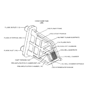
beneath the pre-
amplification chamber.
[0013] In some embodiments, the passage can slope downward from the pre-
amplification
chamber exit to the well chamber entrance.
[0014] In some embodiments, the fluidic path comprises a serpentine channel.
[0015] In some embodiments, the fluidic path can be valveless.
[0016] In some embodiments, the well-substrate can have a plurality of about
100-to about
1500 nanowells.
[0017] In some embodiments, the well-substrate comprises a plurality of wells
having a
diameter of about 50 to about 500 gm.
[0018] In some embodiments, the well-substrate can have a plurality of
nanowells each
having a depth of about 100 gm.
[0019] In some embodiments, the well-substrate can have a plurality of
nanowells where
each well of the plurality of nanowells can range in depth from 25 gm to 1000
gm.
[0020] In some embodiments, the well-substrate can have a plurality of
nanowells wherein
each well of the plurality of nanowells has a width in the range from about 25
um to about
500 um.
[0021] In some embodiments, the well-substrate can have a plurality of
nanowells, each
well having a volume of about 8.5 nl.
[0022] In some embodiments, each well of the plurality of wells can have a
volume in the
range of about 0.1 nL to 500 nL,
[0023] In some embodiments, a portion of the planar frame can define an oil
chamber for
holding a hydrophobic substance.
2
CA 02886484 2015-03-26
WO 2014/052671 PCT/US2013/062042
[0024] In some embodiments, the oil chamber can be in fluidic communication
with the
well chamber.
[0025] In some embodiments, the planar frame can be a scaffold extending from
a base
portion.
[0026] In some embodiments, the first and second planar surfaces can have
first and second
films that fluidically seal the scaffold.
[0027] In some embodiments, the planar frame can be fluidically connected to a
sample
container via the fluidic interface.
[0028] In some embodiments, the well-substrate can be constructed from a
nickel material.
[0029] In some embodiments, the plurality of wells can contain at least one
nucleic acid
primer and/or probe for amplification and/or detection of a specific target.
[0030] In some embodiments, the plurality of wells can contain a molecule,
e.g., an
antibody or a nucleic acid, for the detection of a specific target.
[0031] Some embodiments of the invention relate to a method for providing a
sample fluid
to a fluidic interface of a honeycomb tube. The honeycomb tube can have a
planar frame
defining a fluidic path between a first planar surface and a second planar
surface, each of
which surfaces can be sealed with a thin flexible film. A well-chamber of the
fluidic path can
be filled with a sample fluid, which comprises a sample material to be
analyzed and may
further comprise one or more chemicals for carrying out an assay, such that a
plurality of
wells in the well chamber are filled with the sample fluid. The sample fluid
can then be
evacuated from the well chamber such that the plurality of wells remains at
least partially
filled with the sample fluid.
[0032] In some embodiments, a pre-amplification chamber is present in the
fluidic path
before the well chamber, and the reaction fluid undergoes an amplificaiton
step in the pre-
amplification chamber before filling the well chamber.
[0033] In some embodiments, the pre-amplification chamber can include an upper-
most
exit of the pre-amplification chamber, and the pre-amplification chamber can
be filled at a
level below the upper-most exit of the pre-amplification chamber.
3
CA 02886484 2015-03-26
WO 2014/052671 PCT/US2013/062042
[0034] In some embodiments, the hydrophobic substance is evacuated from the
well
chamber. In some embodiments, the well chamber is subsequently filled with an
aqueous
fluid after evacuation of the hydrophobic substance.
[0035] In some embodiments, heating and/or cooling cycles are applied to both
the first and
second planar surfaces.
[0036] In some embodiments heating and/or cooling cycles are applied to either
the first or
second planar surfaces.
[0037] Some embodiments of the invention relate to carrying out a multiplex
amplification
reaction in the honeycomb tube.
[0038] In some embodiments, the sample fluid is routed along the fluidic path
in a
serpentine manner.
[0039] In some embodiments, the multiplex reaction involves a nested PCR.
[0040] In some embodiments, the multiplex reaction is monitored using
fluorescent
indicators to indicate the presence of an amplicon.
[0041] In some embodiments, the presence of an amplicon is detected using melt-
curve
analysis.
[0042] In some embodiemnts, the multiplex reaction detects the presence or
absence of at
least one single nucleotide polymorphism (SNP).
[0043] In some embodiments, the sample material used in a multiplex reaction
is a body
fluid or is derived from a body fluid.
[0044] In some embodiments, the sample material is a tissue sample, or is
derived from a
tissue sample.
[0045] In some embodiments, a reaction detects the presence or absence of a
protein target.
[0046] In some embodiments, a reaction detects the presence or absence of a
nucleic acid.
[0047] In some embodiments, the nucleic acid is DNA.
[0048] In some embodiments, the nucleic acid is mRNA.
[0049] In some embodiments, the nucleic acid is microRNA.
4
CA 02886484 2015-03-26
WO 2014/052671 PCT/US2013/062042
BRIEF DESCRIPTION OF THE DRAWINGS
[0050] FIGS. 1A, 1B, and 1C respectively show perspective, right-side, and
left-side views
of a honeycomb tube, according to some embodiments of the invention.
[0051] FIGS. 1D and lE respectively right-side views of honeycomb tubes,
according to
some embodiments of the invention.
[0052] FIGS. 2A-2H show cross-sections of portions of the honeycomb tube to
show
various embodiments of the well-substrate 120, according to some embodiments
of the
invention.
[0053] FIG. 3A shows a perspective view of a method for providing the well-
substrate 120
with primer material, according to some embodiments of the invention.
[0054] FIGS. 4A-4E show various methods for filling a well-substrate with a
sample fluid,
according to some embodiments of the invention.
[0055] FIGS. 5A-5F show various sensor assemblies positions in relation to a
honeycomb
tube, according to some embodiments of the invention.
[0056] FIG. 6 shows a fluid control and processing system for providing a
sample fluid to a
honeycomb tube, according to some embodiments of the invention.
[0057] FIGS. 7-13 show steps of an example for performing multiplex PCR SNP
analysis
according to Example 1.
DETAILED DESCRIPTION OF THE INVENTION
[0058] I. Exemplary Honeycomb tube Construction
[0059] As used herein, the term "honeycomb" describes a plurality of wells
that are set into
the surface of a solid substrate at pre-designated locations. In some
embodiments, a
honeycomb tube of this invention contains at least 100 or 200 wells. In some
embodiments,
the honeycomb tube can contain any number of wells between about 100 and 300,
400, 500,
600, 700, 800, 900, 1000, 1100, 1200, 1300, 1400, 1500 or more wells. The
wells can be of
any shape and their locations although predetermined can be arranged in any
format or
pattern on the substrate. As used herein the term "honeycomb tube" can be used
interchangeable with "well chamber," "multi-well reaction chamber," or "multi-
well reaction
tube".
5
CA 02886484 2015-03-26
WO 2014/052671 PCT/US2013/062042
[0060] FIGS. 1A, 1B, and 1C respectively show perspective, right-side, and
left-side views
of a honeycomb tube 100. The honeycomb tube 100 (used interchangeable with a
multi-well
reaction chamber) includes a planar frame 102, which in some embodiments is a
truss-like
structure that is formed from polymer (e.g., polypropylene/acrylic substrate)
or metal material
that is generally PCR compatible. The planar frame 102 can be formed as an
open truss or
scaffold, bounded on the open sides by a first planar substrate 104 and a
second planar
substrate 106.
[0061] The first planar substrate 104 and second planar substrate 106 can be
formed from a
relatively thin polymer film that is adhered or otherwise bonded to the planar
frame 102. In
some embodiments, all or portions of one of the first planar substrate 104 and
second planar
substrate 106 can be integrally formed with the planar frame 102 (e.g., by 3-D
printing,
molding, co-molding, or machining one of the substrates with the planar frame
102). In some
embodiments, the first planar substrate 104 and second planar substrate 106
are constructed
from a transparent material, which is depicted here. Each of the first planar
substrate 104 and
second planar substrate 106 include interior and exterior facing surfaces.
These interior
facing surfaces form fluidic passageways with interior cavities of the planar
frame 102.
[0062] One portion of the planar frame 102 forms a fluidic interface 108. The
fluidic
interface 108 is a structural member which a majority of the planar frame 102
cantilevers.
The fluidic interface 108 can be integrally formed with the planar frame 102.
The fluidic
interface 108 also serves as a mechanical coupling to a cartridge device,
which is described
elsewhere herein. The fluidic interface 108 includes a fluidic inlet 110 and
fluidic outlet 112,
which provide fluidic interfaces to the cartridge device or sample container.
Each of the
fluidic inlet 110 and fluidic outlet 112 are fluidically coupled to a fluidic
path 114 that is
formed in the planar frame 102 between the first planar substrate 104 and
second planar
substrate 106. It should be understood that use of the terms "inlet" and
"outlet" do not limit
function of the fluidic inlet 110 and fluidic outlet 112. Thus, fluid can be
introduced and
evacuated from both or either. In some embodiments, the fluidic path 114 is
valveless, and
thus external increases or decreases in pressures can be applied via the
fluidic inlet 110 and
fluidic outlet 112 by an external system to move fluid within the fluidic path
114, which
extends from the fluidic inlet (110) to the fluidic outlet (112). The cross-
section of the fluidic
path 114 can be round or rectangular, and can have diameters or widths ranging
from about
50 gm to about 2 mm. Typically, the diameters or widths range from about 250
gm to about
1 mm.
6
CA 02886484 2015-03-26
WO 2014/052671 PCT/US2013/062042
[0063] The fluidic path 114 includes a pre-amplification chamber 116 that is
fluidically
connected to a well chamber 118. The well chamber 118 holds a well-substrate
120 (also
referred to herein as a honeycomb) having a plurality of wells (also referred
to herein as
nanowells). The well-substrate 120 can be constructed from a metal, (e.g.,
gold, platinum, or
nickel alloy), ceramic, glass, or other PCR compatible polymer material, or a
composite
material. The well-substrate 120 includes a plurality of wells. In some
embodiments, the
well-substrate 120 can include 100-1000 wells, or more. Wells can be formed in
a well-
substrate 120 as blind-holes or through-holes. The wells can be created within
a well-
substrate 120, for example, by laser drilling (e.g., excimer or solid-state
laser), ultrasonic
embossing, hot embossing lithography, electroforming a nickel mold, injection
molding, and
injection compression molding. In some embodiments, the well-substrate 120 is
adhered to
or co-molded into the planar frame 102, and in some embodiments the well-
substrate 120 is a
molded feature of the planar frame 102. In some embodiments individual well
volume can
range from 0.1 to 1500 nL, typically 0.5 to 200 nL, preferably 0.5 to 50 nL.
For example, in
some embodiments, each well can have a volume of about 0.1, 0.2. 0.3, 0.4,
0.5, 0.6, 0.7, 0.8,
0.9, 1, 1.5, 2, 2.5, 3, 3.5, 4, 4.5, 5, 5.5, 6, 6.5, 7, 7.5, 8, 8.5, 9, 9.5,
10, 11, 12, 13, 14, 15, 16,
17, 18, 19, 20, 15, 30, 35, 40, 45, 50, 55, 60, 65, 70, 75, 80, 85, 90, 95,
100, 110, 120, 130,
140, 150, 160, 170, 180, 190, 200, 225, 250, 275, 300, 325, 350, 375, 400,
425, 450, 475, or
500 nL. Well dimensions can have any shape, for example, circular, elliptical,
square,
rectangular, ovoid, hexagonal, octagonal, conical, and other shapes well known
to persons of
skill in the art. Further, well shapes may have cross-sectional areas that
vary along an axis.
For example, a square hole may taper from a first size to a second size that
is a fraction of the
first size. In some embodiments, well dimensions can be square, with diameters
and depths
being approximately equal. In some embodiments, the well diameter and depths
are not
equal. In some embodiments, walls that define the well are non-parallel. In
some
embodiments, walls that define the well converge to a point. Well dimensions
can be derived
from the total volume capacity of the well-substrate 120. In some embodiments,
well depths
can range from 25 gm to 1000 gm. In some embodiments, for example, wells can
have a
depth of 25, 50, 75, 100, 150, 200, 250, 300, 350, 400, 450, 500, 550, 600,
650, 700, 750,
800, 850, 900, 950, or 1000gm. In some embodiments, well diameter can range
from about
25 gm to about 500 m. In some embodiments, for example, the wells can have a
width of
25, 50, 75, 100, 125, 150, 175, 200, 225, 250, 275, 300, 325, 350, 375, 400,
425, 450, 475, or
500 m.
7
CA 02886484 2015-03-26
WO 2014/052671 PCT/US2013/062042
25uL Tube 65uL Tube 100uL Tube
Length (mm) Length (mm) Length (mm)
4.6 7.1 9.0
Diameter Depth WellPitch* # of Total # of
Total # of Total
volume
wells/side Wells wells/side Wells wells/side Wells
(mm) (mm) (nL) (mm)
0.1 0.1 0.8 0.23 20 400 31 961 39 1521
0.15 0.15 2.7 0.3 15 225 24 576 30 900
0.2 0.2 6.3 0.35 13 169 20 400 26 676
0.25 0.25 12.3 0.4 11 121 18 324 22 484
Chart I ¨ Exemplary Well Substrate Dimensions (metric)
[0064] Portions of the well-substrate 120 and/or the interior of the first
planar substrate 104
and/or second planar substrate 106 can be modified to encourage or discourage
fluid
adherence. For example, surfaces defining the wells can be coated with a
hydrophilic
material (or modified to be hydrophilic), and thus encourage retention of
fluid. Further,
planar surfaces (surrounding interior surfaces defining the wells) can be
coated with a
hydrophobic material (or modified to be hydrophobic), and thus discourage
retention of fluid
thereon. Other surface treatments can be performed such that fluid is
preferably held within
the wells, but not on upper surfaces so as to encourage draining of excess
fluid.
[0065] The wells of the well-substrate 120 can be patterned to have a simple
geometric
pattern of aligned rows and columns, or patterns arranged diagonally or
hexagonally. In
some embodiments, the wells of the well-substrate 120 can be patterned to have
complex
geometric patterns, such as chaotic patterns or isogeometric design patterns
as described by
Schillinger et at., Computer Methods in Applied Mechanics and Engineering
January 22,
2012. The wells can be geometrically separated from one another and/or feature
large depth
to width ratios to help prevent cross-contamination of reagents during the
filling process. In
some embodiments, methods as disclosed herein and methods well known to
persons of
ordinary skill in the art can be used to prevent reagent cross-contamination.
[0066] As shown in FIG 1A, a portion of the well-substrate 120 can be
connected to the
second planar substrate 106, such that a gap is formed (so as to allow fluid
to pass) between a
front portion of the well-substrate 120 and the first planar substrate 104.
The pre-
amplification chamber 116, when present, includes a pre-amplification chamber
exit 122,
which is located at the upper-most portion of the pre-amplification chamber
116 (in the
orientation shown). A well chamber entrance 124 is located at a lower-most
portion of the
well chamber 118. A down-ward sloping intermediate passage 126 separates the
pre-
8
CA 02886484 2015-03-26
WO 2014/052671 PCT/US2013/062042
amplification chamber exit 122 and the well chamber entrance 124. A lower-most
inlet
passage 128 and an upper-most outlet passage 130 make up the remaining
portions of the
fluidic path 114.
[0067] In some embodiments, the planar frame 102 includes one or more (i.e.,
at least one)
of auxiliary chambers 132, which are useable to provide process fluids, such
as oil or other
chemical solutions to the pre-amplification chamber 116, the well chamber 118,
and/or any
other portion of the fluidic path 114. Such auxiliary chambers 132 can be
fluidically
connected to portions of the fluidic path 114 via one or more membranes,
valves and/or
pressure severable substrates (i.e. materials that break when subjected to a
pre-determined
amount of pressure from fluid within an auxiliary chamber or adjacent portion
of the fluidic
path 114) such as metal foil or thin film.
[0068] In some embodiments, the fluidic path 114 can include torturous
portions as shown
in Fig. 1D. A torturous path between the inlet passage 128 and the well
chamber 118 can be
helpful for control and handling of fluid processes. It has been found that a
torturous path
can help reduce formation of gas bubbles that can interfere with flowing oil
through the
fluidic path. The honeycomb tube 100' shown in Fig. 1D is largely the same as
the
honeycomb tube 100 shown in Figs. 1A-1C, however, the intermediate passage
126' includes
a plurality of elongated channel portions connected in a serpentine manner.
Here, three
elongated channel portions are depicted, however, more or less portions can be
used.
Generally, at least 2 channel portions are used, and in some embodiments, 2-10
elongated
channel portions are used.
[0069] In some embodiments, the fluidic path 114 includes extensive torturous
portions, as
shown in Fig. 1E. The honeycomb tube 100" shown here is largely the same as
the
honeycomb tube 100 shown in Figs. 1A-1C, however, the intermediate passage
126" extends
throughout a majority of the structure of the honeycomb tube 100". In this
manner, elongated
channel portions of the intermediate passage 126' can be made relatively wide
to resemble
elongated chambers in which amplification can take place. Here, four elongated
channel
portions are depicted, however, more or less portions can be used. Generally,
at least 2
channel portions are used, and in some embodiments, 2-10 elongated channel
portions are
used. Sharply angled interior curves that define the intermediate passage 126'
between the
elongated channels are bulbous to reduce cross-sectional area between
elongated channels.
The reduced cross-sectional area around corners helps to reduce flow rate
differentials
9
CA 02886484 2015-03-26
WO 2014/052671 PCT/US2013/062042
between fluids at the outer radius of the curve as compared to fluids at the
inner radius of the
curve. If such flow rate differentials are too great, then unwanted cavitation
causing bubble
formation can result. Here, the widths of the turns are approximately 50% of
the widths of
the elongated channel portions. In some embodiments, the widths of the turns
are range from
10-90% of the widths of the elongated channel portions. In some embodiments,
the widths of
the turns vary with respect to one another.
[0070] As described above, the channel geometry shown in Fig. lE can be
beneficial for
control and handling of fluid processes. Although a pre-amplification chamber
is not shown,
one or more may be included depending on the particular application of the
honeycomb tube
100". It should be understood that with the geometry shown, if a sample
includes very few
copies of target (i.e. 1 or 2), then after amplification the amplified target
may not be mixed
and evenly distributed because of the linear nature of the serpentine channel.
Thus, it may be
necessary to move the fluid back into the cartridge (either into the syringe
tube or a separate
chamber) to mix and evenly distribute the amplicons before filling the wells
of the well
chamber.
[0071] FIGS. 2A-2G show cross-sections of portions of the honeycomb tube to
show
various embodiments of the well-substrate 120.
[0072] FIG. 2A shows an embodiment where wells of the well-substrate 120 are
constructed via blind-holes made into the planar frame 102. In this
embodiment, the second
planar substrate 106 is integrally formed with the planar frame 102, such that
they are
essentially one piece of material. Primer/probe materials 134 are shown placed
into each
well of the well-substrate 120.
[0073] FIG. 2B shows an embodiment where wells of the well-substrate 120 are
constructed via through-holes made into a substrate, such as a polymer film,
that is bonded
onto the planar frame 102. For example, a separate substrate can be drilled to
form a well-
substrate of through holes, and subsequently adhered or welded onto the planar
frame 102. In
this embodiment, the second planar substrate 106 is integrally formed with the
planar frame
102, such that they are essentially one piece of material. In some
embodiments, blind holes
can be formed within the second planar substrate 106, which can be bonded onto
the planar
frame 102.
[0074] FIG. 2C shows an embodiment where wells of the well-substrate 120 are
constructed via through-holes formed within a portion of the planar frame 102.
In this
CA 02886484 2015-03-26
WO 2014/052671 PCT/US2013/062042
embodiment, the second planar substrate 106 is integrated with the planar
frame 102 and the
well-substrate 120 is a separate component that is adhered or welded to a
pocket within the
planar frame 102.
[0075] FIG. 2D shows an embodiment where wells of the well-substrate 120 are
constructed via through-holes formed within a portion of the planar frame 102,
as shown in
FIG. 2C. However, in this embodiment, a gas permeable membrane 136 is located
between
the planar frame 102 and the second planar substrate 106. The membrane 136
enables gas to
be evacuated from the wells through the membrane, while not allowing fluid to
pass through.
The gas permeable membrane can be adhered to the well-substrate by a gas
permeable
adhesive. In some embodiments, the membrane 136 is constructed from
polydimethylsiloxane (PDMS), and has a thickness ranging from 20-1000 gm, and
in some
embodiments has a thickness ranging from 100-200 gm.
[0076] FIG. 2E shows an embodiment where wells of the well-substrate 120 are
constructed via blind-holes formed within a portion of the planar frame 102.
In this
embodiment, the second planar substrate 106 is integrated with the planar
frame 102 and the
well-substrate 120 is a separate component that is adhered or welded to a
pocket within the
planar frame 102.
[0077] All or portions of the well-substrate 120 can be contain conductive
metal portions
(e.g., gold) to enable heat transfer from the metal to the wells. For example,
the portion of
the well-substrate 120 that is placed against the second planar substrate 106
can be a metal
plate or coating. In some embodiments, interior surfaces of the wells can be
coated with a
metal to enable heat transfer.
[0078] FIG. 2F shows an embodiment that is constructed similarly to the
embodiment of
Fig. 2D. However, here the well-substrate is positioned a mid-point between
the first and
second substrates. The gas permeable membrane 136 can be adhered to the well-
substrate by
a gas permeable adhesive. As with the embodiment shown in Fig. 2D, air can
exit through
the gas permeable membrane to the back of the wells during liquid filling.
After PCR buffer
fills the wells and rehydrates the dried primer sets in the wells, an
isolation oil or thermally
conductive liquid can fill both sides of the well-substrate 120 to prevent
cross-talk.
[0079] FIG. 2H shows an embodiment that is constructed similarly to the
embodiment of
Fig. 2F. However, here, a membrane is not included. Thus, processing fluids
can be exposed
to both sides of the well-substrate 120. After PCR buffer fills the wells and
rehydrates the
11
CA 02886484 2015-03-26
WO 2014/052671 PCT/US2013/062042
dried primer sets in the wells, an isolation oil or thermally conductive
liquid can fill both
sides of the well-substrate 120 to prevent cross-talk.
[0080] FIG. 2H shows an embodiment of the well-substrate 120 useable with any
of the
embodiments shown disclosed herein, for example as shown in Figs. 2A-2F. Here,
the wells
121 of the well-substrate 120 is shaped to taper from a larger diameter to a
smaller diameter,
similar to a cone. It has been found that cone-shaped wells offer an advantage
during primer
application, because the sloped walls of the wells enable use of a non-contact
deposition
method (e.g., ink jet) for depositing liquid reagent, which includes the
primer material.
Further, the cone-shaped wells enable easier application of a liquid reagent
for both contact
and non-contact methods of liquid reagent application, since the conical shape
aids in drying.
It has also been found that the cone-shaped wells help prevent bubbles and
leaks when the
gas permeable membrane 136 is present.
[0081] FIG. 3A shows a method for providing the well-substrate 120 with primer
material.
As shown, a commercially available printing pin can be used to fill the wells
with a liquid
primer, which can be dried in the well or the liquid filled well can be sealed-
over after filling.
In some embodiments, after the well-substrate 120 is provided with primer in a
liquid form,
the primer material can be dried such that only a primer residue remains
adhering to each
well for later liquefaction. Examples of such pins (and associated systems)
include the
946MP(x) series of pins from ArrayIt Corporation, located at 524 East Weddell
Drive,
Sunnyvale, CA 94089, USA. Methods disclosed by Hasan et at., U.S. Pub. No.
2009/0054266 and Hess et at., U.S. Patent No. 6,716,629, can also be used to
provide primer
material. During the application process, the printing pin can be configured
to make contact
with the well-substrate 120. In some embodiments, a non-contact process can be
used for
providing the liquid reagent (e.g. primer) to the well resulting with dried
reagent on one or
more walls that define the well, for example a droplet-based method such as
ink-jet printing,
or other suitable non-contact processes known to persons of skill in the art.
[0082] II. Sample Loading into Honeycomb Tubes
[0083] FIGS. 4A and 4B show a method of filling the well-substrate 120 with a
sample
fluid. In FIG. 4A a sample fluid is advanced (e.g., via pressure) between the
well-substrate
120 and the first planar substrate 104. As the fluid passes over the well-
substrate 120, each
well becomes filled with fluid, which is primarily retained within the wells
via surface
tension. As recited above, portions of the well-substrate 120, such as the
walls defining the
12
CA 02886484 2015-03-26
WO 2014/052671 PCT/US2013/062042
wells, can be coated with a hydrophilic substance or treated to become
relatively more
hydrophilic, and thus encourage complete and uniform filling of the wells as
the sample fluid
passes over. Additionally, other surfaces of the well-substrate 120, such as
top surfaces
surrounding the well surfaces, can be coated with a hydrophobic substance or
treated to
become relatively more hydrophobic such that the fluid sample is only retained
in the wells
and not on adjacent surfaces thereby reducing inconsistent testing results.
Additionally, the
interior surface of the first planar substrate 120, can be coated or treated
for a hydrophobic
effect. In FIG. 4B, it can be seen that only the wells are filled after the
sample fluid is
retreated. In some embodiments, a fluid sample can be advanced as shown in
FIG. 4B',
followed by a pocket of air, thus eliminating the need to withdraw the sample
as illustrated in
the exemplary embodiment shown in FIG. 4B. Filling methods such as
"discontinuous
wetting" can also be used as disclosed by Jackman et at., Anal Chem., 1998,
70, 2280-2287
and by Hatch et at., MULTILAYER HIGH-DENSITY 3D NANO WELL ARRAYS FOR
DIGITAL BIOLOGY, 15th Int'l. Conference on Miniaturized Systems for Chemistry
and
Life Sciences, Oct. 2-6, 2011, 269-271. Generally, the well-substrate 120
should be de-
wetted as quickly as possible to avoid cross-contamination of different
primers within the
wells.
[0084] FIGS. 4C and 4D show another method of filling the well-substrate 120
with a
sample fluid. In FIG. 4C, the well-substrate 120 is filled according to a
combination of the
techniques shown in FIGS. 4A and 4B. However, the sample fluid is trailed by a
pocket of
oil. Although the oil in Fig 4C is shown directly contacting the sample fluid,
an air gap can
be provided between the oil cap and the sample fluid.
[0085] As shown in FIG. 4D, after each well is filled with sample fluid, the
oil can "cap"
off each well, which can aid in reducing evaporation when the well-substrate
120 is subjected
to heat cycling. In some embodiments, after the wells have been filled, oil
can be introduced
from the top of the chamber and withdrawn from the chamber entrance 124 as
shown in FIG.
4D'. In both of the embodiments shown in FIG. 4D and FIG. 4D', after the wells
have been
capped with oil, an aqueous solution can fill the chamber 118 to improve
thermal
conductivity. In some embodiments, the stationary aqueous solution can be
pressurized
within the chamber 118 to halt the movement of fluid and any bubbles.
[0086] In some embodiments, after the wells have been filled, oil can be held
stationary
within the chamber during heat cycling, as shown in FIG. 4D". In some
embodiments, the
13
CA 02886484 2015-03-26
WO 2014/052671 PCT/US2013/062042
stationary oil can be pressurized within the chamber 118 to halt the movement
of fluid and
any bubbles.
[0087] Oil such as mineral oil can be used for isolation of each well and to
provide thermal
conductivity. However, embodiments of the invention are not limited to "oil".
Any thermal
conductive liquid, such as fluorinated liquids (e.g., 3M FC-40) can be used.
Hence,
references to "oil" in this disclosure should be understood to include such
alternatives.
[0088] In some embodiments, after the wells have been filled with sample fluid
as shown in
FIG. 4C, oil can follow the sample fluid to cap the wells and is maintained
within the well
chamber 118. An experiment detailing this embodiment was performed as
described in
Example 3 and as shown in FIG. 4E.
[0089] FIGS. 5A and 5B show an exemplary sensor assembly positioning for
detecting
reactions at the well-substrate 120. In some embodiments, sensor assembly A is
positioned
directly adjacent or against the first planar substrate 104. In some
embodiments, a second
sensor assembly B is positioned directly adjacent or against the second planar
substrate 106.
Each sensor assembly can include excitation and/or detection devices for PCR
testing. In
some embodiments, the sensors are optical sensors for the excitation and
detection of
fluorescence.
[0090] FIG. 5C shows an exemplary sensor assembly configuration that can be
used in lieu
of or in combination with the configuration of FIGS. 5A and 5B. Here, sensor
assembly A is
positioned along the forward edge of the honeycomb tube 100. In some
embodiments, a
second sensor assembly B is included. In some embodiments, one or all of the
sensor
assemblies A and B of FIGS. 5A and 5B are used in combination with one or all
of the sensor
assemblies A and B of FIGS. 5C.
[0091] FIG. 5D shows an exemplary sensor assembly configuration. In some
embodiments, this sensor assembly configuration can be used in conjunction
with the
configuration shown in FIGS. 5A-5C. The sensor assembly includes a CCD/CMOS
detector
coupled to a fiber optic face plate (FOFP). A filter is layered on top of the
FOFP, and placed
against or adjacent to the target, which here is the well-substrate 120. In
some embodiments,
the filter can be layered (bonded) directly on top of the CCD with the FOFP
placed on top as
shown in FIG. 5E.
14
CA 02886484 2015-03-26
WO 2014/052671 PCT/US2013/062042
[0092] FIG. 5F shows another exemplary sensor assembly configuration. In some
embodiments, this configuration can be used in conjunction with one or more of
the
configurations shown in FIGS. 5A-5C. Here, a CCD/CMOS detector coupled to a
double
lens configuration with a filter placed in between. In some embodiments, the
filter can be
bonded to the CCD/CMOS detector.
[0093] III. Methods for Use
[0094] In some embodiments, a sample fluid is introduced into the fluidic
inlet 110 and
through inlet passage 128. The pre-amplification chamber 116 can then be
filled with the
sample fluid. The pre-amplification chamber 116 can include one or more
chemicals to cause
a desired chemical reaction, and thereby amplify the fluid therein. In some
embodiments, the
fluid can be maintained within the pre-amplification chamber 116, up to, but
not past, the pre-
amplification chamber exit 122, until the desired reaction occurs. The fluid
is then passed
through the pre-amplification chamber exit 122 and into the downward sloping
intermediate
passage 126. The fluid then passes the well chamber entrance 124 and fills the
well chamber
118. In some embodiments, after amplification of the fluid in the pre-
amplification chamber,
the fluid is withdrawn from the pre-amplification chamber through the fluid
inlet and into a
separate chamber in the fluid processing cartridge for mixing, and then is
returned through
the fluid inlet to pass through the pre-amplification chamber to enter the
well chamber. The
wells of the well-substrate 120 can then be filled, for example, according to
a method as
shown in FIGS. 4A-4D". Once the wells of the well-substrate 120 are filled,
the fluid can be
evacuated from the well chamber 118, either through the outlet passage 130, or
back through
the inlet passage 128. In some embodiments, an oil, such as mineral oil, can
be coated over
the filled wells to prevent evaporation during thermal cycling. In some
embodiments,
pressure ranging from 5 to 20psi will applied to the well-chamber 118. Thus,
PCR buffer as
well as any thermally conductive liquid (oil) are under compression to hold
PCR liquid and
any small bubbles - possibly generated during rehydration of the dried
primers. This
application of pressure can cause immobilization of any generated bubbles, so
that no optical
interference from moving bubbles and liquid occurs. In some embodiments, a
hydration
fluid, such as distilled water, can be heated within the pre-amplification
chamber 116, or one
of the auxiliary chambers 132, such that the well chamber 118 has 100%
humidity, or
sufficient enough humidity to prevent over evaporation during thermal cycling.
After filling
is complete, the well-substrate 120 can be heated by an external device that
is in thermal
contact with the honeycomb tube 100 to perform thermal cycling for PCR. In
some
CA 02886484 2015-03-26
WO 2014/052671 PCT/US2013/062042
embodiments, non-contact methods of heating can be employed, such as RFID,
Curie point,
inductive, or microwave heating. These and other non-contact methods of
heating are well
known to persons of ordinary skill in the art and can be readily applied to
the honeycomb
tube as disclosed herein. During thermal cycling, the honeycomb tube can be
monitored for
chemical reactions via the sensor arrangements described in FIGS. 5A-5E.
[0095] A variety of biological assays can be performed using the honeycomb
tube 100,
typically for the purpose of indicating the presence of at least one analyte
of interest in a test
sample. These assays include, but are not limited to, binding assays based on
specific
binding affinity between a pre-selected pair of molecules (such as an antibody-
antigen
binding pair or two polynucleotide sequences with sufficient complementarity),
nucleic acid
amplification reactions relying on certain pre-determined nucleotide sequence-
based criteria,
and chemical reactions indicative of the presence of molecules of pre-defined
activity (such
as enzymes).
[0096] In some embodiments, analytic agents or probes that are deposited in
the
honeycomb tube in a pre-determined arrangement, for example, "bait" proteins
or nucleic
acids, are directly immobilized on the surface of a solid substrate with
minimal structural
alternation or modification of the substrate surface. In other words, the
agents or probes are
essentially "spotted" on the surface and arranged and confined within a 2-
dimensional space.
In some embodiments, the substrate can be manufactured to form an arrangement
of multiple
wells or indentations of pre-determined dimensions to house the agents or
probes, which can
be permanently immobilized within the wells or indentations, or temporarily
confined within
the wells or indentations for the assay time duration. In other words, the
analytic probes will
be confined within a 3-dimensional space.
[0097] Material suitable to serve as analytic probes of the honeycomb tube
includes
selection of proteins (e.g., full length proteins such as antibodies, protein
fragments, or short
peptides), nucleic acids (e.g., DNA, RNA, microRNA), carbohydrates, lipids,
tissues, cells, or
molecules of virtually any and all chemical nature. In other words, any
material/molecule
that is known to be used to make microarrays for multiplexing assays can be
used in the
honeycomb testing tube of this invention.
[0098] IV. Detection of an Analyte of Interest
[0099] One aspect of the present invention relates to the monitoring of an
optical signal
(using the sensor configurations of FIGS. 5A-5E) indicative of the presence in
a test sample
16
CA 02886484 2015-03-26
WO 2014/052671 PCT/US2013/062042
of at least one analyte of interest, for example, a target protein (e.g., an
antibody of a
particular antigenicity), a target cell, a target gene, a target sequence of
genes, a target mRNA
transcription, or a target nucleic acid. Such target analyte(s) can be of any
origin: viral,
bacterial, fungal, parasitic (e.g., from a protozoan), animal, or human
origin. For example,
viral proteins, antibodies against viral antigens, or DNA/RNA sequences
derived from a
bacterial, or viral genome can be the analytes of interest for detection in
test samples.
Exemplary non-limiting target analytes can include a nucleic acid sequence
such as a micro
RNA, mammalian genes, genetic variants of a mammalian gene, such as various
genetic
mutants, allelic variants, or epigenetic variations (exhibiting different
profiles in methylation
status) within oncogenes, tumor suppressor genes, or any other genes that have
been
implicated as relevant to certain diseases and conditions, can be the focus of
detection in the
application of the honeycomb testing tube of this invention. Exemplary viruses
the genes
and/or proteins of which can be targets of interest can include but are not
limited to human
immunodeficiency virus-1 (HIV-1), human cytomegalovirus (CMV), hepatitis C
virus
(HCV), Hepatitis B virus (HBV), Human Papiloma Virus (HPV), enterovirus,
varicella-zoster
virus; flaviviruses, hepadnaviruses, herpesviruses, noroviruses,
orthomyxoviruses,
parvoviruses, papovaviruses, paramyxoviruses, pestiviruses, picornaviruses,
and influenza.
Exemplary bacteria the genes and/or proteins of which can be targets of
detection are
mycobacterium tuberculosis (TB), bacillus anthracis, legionella pneumophilia,
listeria
monocytogenes, neisseria gonorrhoeae, chlamydia trachomatis, neisseria
meningitides,
xtaphylococcus aureus, helicobacter pylori, and enterococcus faecalis.
Exemplary human
genes of potential interest are p53, BRCA1 and BRCA2, Her2/Neu and other EGFR
family
members, BCR-ABL, PTEN, RAS, RAF, Src, RB, Myc, VEGF, topoisomerase, and the
APOE84 allele.
[0100] Basic techniques of detecting and/or quantifying various analytes of
interest can be
found in, for example, Sambrook and Russell, Molecular Cloning, A Laboratory
Manual (3rd
ed. 2001); Kriegler, Gene Transfer and Expression: A Laboratory Manual (1990);
Ausubel et
al., Current Protocols in Molecular Biology (1994); and Harlow & Lane,
Antibodies, A
Laboratory Manual (1988).
[0101] For the purpose of detecting the presence of a protein of any
particular identity, one
can employ a variety of binding affinity-based assays, such as immunological
assays. In
some embodiments, a sandwich assay format can be performed by capturing a
target protein
from a test sample with an antibody (which is immobilized to a pre-determined
spot in a
17
CA 02886484 2015-03-26
WO 2014/052671 PCT/US2013/062042
honeycomb format or confined within a pre-determined well of the honeycomb)
having
specific binding affinity for the polypeptide. The presence of the protein can
then be
indicated with a secondary antibody attached to a detectable label, such as a
fluorescence-
generating molecule.
[0102] For the purpose of detecting the presence of a nucleic acid of
interest, a probe, or a
molecule containing a polynucleotide sequence substantially complementary to
the target
nucleic acid sequence and capable of hybridizing to the target sequence based
on the Watson-
Crick base-pairing, is typically used. Again, the probe can be immobilized or
spotted to the
surface of a solid substrate at a pre-determined location, or in some
embodiments, the probe
can be confined to a well at a pre-determined location within a predetermined
pattern on the
substrate. Depending on the nature of the target polynucleotide being
detected, for example,
whether it is double-stranded or single-stranded, a detection probe can be
substantially
identical in sequence to the target sequence or substantially identical in
sequence to the
complementary sequence of the target sequence. In other words, the probe is
capable of
specially bind to the target nucleotide sequence. In some cases, the probe can
contain one
binding segment to the target nucleotide as well as a non-binding segment, so
long as the
presence of the non-binding segment does not interfere with the specific
binding between the
binding segment and the target nucleic acid. Typically, the binding segment
will have at least
8, often at least 10, 12, 15, 20, 25, 30 or even more, contiguous nucleotides
that are
complementary to either strand of the target polynucleotide sequence, in order
to ensure
specific recognition of the target sequence. A probe can, in some embodiments,
include a
light-emitting moiety for easy detection, e.g., a fluorescent or luminescent
molecule such as
fluorescein, rhodamine, Texas Red, phycoerythrin, hydroxycoumarin,
aminocoumarin,
cascade blue, Pacific Orange, lucifer yellow, allophycocyanin, TruRed, FluorX,
or a
lanthanide.
[0103] In some embodiments, different fluorescent indicators are employed for
indicating
the presence of distinct polynucleotide sequences. In some embodiments, a
melting point-
based detection method can be effective for detecting the presence of distinct
target
polynucleotide sequences when a common fluorescent indicator is used.
[0104] Aside from the binding assay format where detection of an analyte of
interest is
made directly based on binding affinity of the analyte to the analytic agent
provided in the
honeycomb tube, an amplification-based assay system for detection and/or
quantitation of
18
CA 02886484 2015-03-26
WO 2014/052671 PCT/US2013/062042
nucleic acids of interest offers a broad spectrum of applications. In this
amplification-based
system, one or more nucleic acids of interest is detected and/or quantified
upon completion of
a sequence-specific amplification reaction. Furthermore, for the purpose of
detecting a target
nucleic acid by an amplification-based method, multiple sets of primers can be
included in
each well to permit detection carried out in the nested PCR format, for
example, the first set
of primers can define a portion of the target sequence and generate an
amplicon that allows
further amplication by one or more subsequent set of primers.
[0105] In some embodiments, the nucleic acid of interest is a DNA molecule.
Sequence-
specific amplification is performed by providing at least one set of primers,
free nucleotides,
and appropriate DNA or RNA polymerase in each well of the honeycomb format,
and then
subjecting the honeycomb tube to appropriate temperatures and time durations
to achieve the
synthesis and amplification of any target polynucleotide sequence.
[0106] Each primer is typically an oligonucleotide (which can be either
natural or
synthetic) capable, upon forming a duplex with a polynucleotide template by
base-pairing, of
acting as a point of initiation of nucleic acid synthesis and being extended
from its 3' end
along the template so that an extended duplex is formed. Extension of a primer
is usually
carried out with a nucleic acid polymerase, such as a DNA or RNA polymerase.
The
sequence of nucleotides added in the extension process is determined by the
sequence of the
template polynucleotide. In most embodiments, primers are extended by a DNA
polymerase.
Frequently, primers have a length in the range of from 6 to 40 nucleotides,
typically from
about 12 to about 20 nucleotides. Primers are employed in a variety of nucleic
acid
amplification reactions, for example, linear amplification reactions using a
single primer, or
polymerase chain reactions (PCR), employing two or more primers. Guidance for
selecting
the lengths and sequences of primers for particular applications is well known
to those of
ordinary skill in the art, see, e.g., Dieffenbach, editor, PCR Primer: A
Laboratory Manual,
2nd Edition (Cold Spring Harbor Press, New York, 2003).
[0107] In the context of a nucleic acid amplification reaction such as a PCR,
the
amplification product of a target polynucleotide sequence is referred as an
"amplicon."
Amplicons are a population of polynucleotides resulted from primer extension,
usually in the
form of double stranded polynucleotides. Amplicons can be produced by a
variety of
amplification reactions whose products are replicates after multiple rounds of
amplification
of one or more target nucleic acids. Generally, amplification reactions
producing amplicons
19
CA 02886484 2015-03-26
WO 2014/052671 PCT/US2013/062042
are template-driven in the base pairing of reactants: both nucleotides and
oligonucleotide
primers have complements in a template polynucleotide or target polynucleotide
sequence.
Such complementarity is required for the production of reaction products, or
amplicons. In
some cases, template-driven reactions are primer extensions with a nucleic
acid polymerase
or oligonucleotide ligations with a nucleic acid ligase. Such reactions
include, but are not
limited to, polymerase chain reaction (PCR), linear polymerase reaction,
ligase chain reaction
(LCR), strand-displacement reaction (SDA), nucleic acid sequence-based
amplification
(NASBA), rolling circle amplifications, and the like, see, e.g., Mullis et
at., U.S. Patent Nos.
4,683,195; 4,965,188; 4,683,202; and 4,800,159 (PCR); Gelfand et at., U.S.
Patent No.
5,210,015 (real-time PCR using TaqMan probes); Wittwer et al.,U.S. Patent No.
6,174,670;
Landegren et al.,U U.S. Patent No. 4,988,617 (LCR); Birkenmeyer et at., U.S.
Patent No.
5,427,930 (gap-LCR); Kacian et at., U.S. Patent No. 5,399,491 (NASBA); Walker,
U.S.
Patent Nos. 5,648,211 and 5,712,124 (SDA); Lizardi, U.S. Patent 5,854,033;
Aono et at.,
Japanese Patent Application Publication No. JP 4-262799 (rolling circle
amplification); and
the like. In some embodiments, amplicons of one or more target nucleic acids
are produced
by one or more rounds of PCR, e.g., nested PCR, performed in the honeycomb
tube of the
present invention.
[0108] A polymerase chain reaction, or PCR, is an enzyme-mediated reaction for
the in
vitro amplification of specific DNA sequences by the simultaneous, multiple
rounds of
primer extensions of complementary strands of DNA. In other words, a PCR is a
reaction for
making multiple copies or replicates of a target nucleic acid flanked by
primer binding sites,
such reaction comprising one or more repetitions of the following steps: (i)
denaturing the
target nucleic acid; (ii) annealing primers to the primer binding sites; and
(iii) extending the
primers by a nucleic acid polymerase in the presence of nucleoside
triphosphates. The
reaction is typically cycled through different temperatures optimized for each
of the
denaturing, annealing, and extension steps. Particular temperatures, time
durations at each
step, and rates of change between steps depend on many factors well-known to
those of
ordinary skill in the art, see, e.g., McPherson et at., editors, PCR: A
Practical Approach and
PCR2: A Practical Approach (IRL Press, Oxford, 1991 and 1995, respectively).
For
example, in a conventional PCR using Taq DNA polymerase, a double stranded
target
nucleic acid can be denatured at a temperature >90 C, primers annealed at a
temperature in
the range 50-75 C, and primers extended at a temperature in the range 72-78 C.
CA 02886484 2015-03-26
WO 2014/052671 PCT/US2013/062042
[0109] The term "PCR" encompasses derivative forms of the reaction, including
but not
limited to, reverse transcription (RT)-PCR, real-time PCR, nested PCR,
quantitative PCR,
multiplexed PCR, and other similar variations. For these various PCR assays,
typical
reaction volumes can range from nanoliters, e.g., about 0.1- to about 500 nL,
to microlitters,
e.g., about 1-about 5 L, and can be readily contained within the wells of the
honeycomb
testing tubes of the present invention, thus allowing a rapid multiplexing
analysis. In some
non-limiting exemplary embodiments, the reaction volume within each of the
wells of the
honeycomb tube are about 0.1, 0.2, 0.3, 0.4, 0.5, 0.6. 0.7, 0.8, 0.9. 1, 1.5,
2, 2.5, 3, 3.5, 4, 4.5,
5, 5.5, 6, 6.5, 7, 7.5, 8, 8.5, 9, 9.5, 10, 12, 14, 16, 18, 20, 25, 30, 35,
40, 45, 50, 55, 60, 65, 70,
75, 80, 85, 90, 95, and 100 nL.
[0110] A reverse transcription PCR or RT-PCR is a particularly powerful tool
for the
detection and analysis of RNA in a sample. An RT-PCR is a PCR preceded by a
reverse
transcription reaction when a target RNA is converted to a complementary
single stranded
DNA, which is then amplified in the regular PCR process, see, e.g., Tecott et
at., U.S. Patent
No. 5,168,038.
[0111] A real-time PCR is a PCR process during which the amount of reaction
products,
i.e., amplicons, is monitored at the same time while the reaction proceeds.
There are many
forms of real-time PCR that differ mainly in the means of detection used for
monitoring the
reaction product(s), see, e.g., Gelfand et at., U.S. Patent No. 5,210,015
(TaqMan probes);
Wittwer et al., U.S. Patent Nos. 6,174,670 and 6,569,627 (intercalating dyes);
Tyagi et al.,
U.S. Patent No. 5,925,517 (molecular beacons). Detection chemistries for real-
time PCR are
reviewed in Mackay et al., Nucleic Acids Research, 30: 1292-1305 (2002).
[0112] A nested PCR is a PCR process that involves at least two stages of
amplification
where the amplicon of a first stage PCR using a first set of primers becomes
the template for
a second stage PCR using a second set of primers. At least one primer of the
second set of
primers has sequence complementarity and can hybridize to the target
polynucleotide
sequence at a location that is between the hybridization sites of the two
primers of the first
set, i.e., at a location within the sequence of the amplicon of the first
stage PCR.
[0113] A multiplexed PCR is a PCR process where amplification of multiple
potential
target polynucleotide sequences are simultaneously carried out in the same
reaction mixture,
see, e.g., Bernard et at., Anal. Biochem., 273: 221-228 (1999) (two-color real-
time PCR).
The honeycomb assay format of the present invention is suitable for carrying
out multiplexed
21
CA 02886484 2015-03-26
WO 2014/052671 PCT/US2013/062042
PCR. A distinct set of primers is contained in a well-intended for the
amplification and
detection of a distinct target polynucleotide sequence. Typically, there are a
number of repeat
wells containing the same primers as duplicate wells in the honeycomb well
arrangement.
For example, in a non-limiting exemplary embodiment, one entire honeycomb well
arrangement can include different pre-made reaction mixtures each containing a
distinct
primer set selected from a total of up to 8, 16, 25, 50 or even 100different
sets of primers,
with a cluster of 8 replicate wells provided for each reaction mixture
containing a distinct set
of primers.
[0114] A quantitative PCR is a PCR process that allows one to measure the
abundance of
one or more specific target sequences in a sample. Quantitative PCRs can
involve measuring
both absolute quantitation and relative quantitation of the target sequences.
Quantitative
measurements are made using one or more reference sequences that can be
assayed
separately or together with a target sequence. The reference sequence can be
endogenous
(naturally existing) or exogenous (artificially added) to a sample, and in the
latter case, can
comprise one or more competitor templates. Typical endogenous reference
sequences
include segments of transcripts of the following genes: 13-actin, GAPDH,132-
microglobulin,
ribosomal RNA, and the like. Techniques for quantitative PCR are well-known to
those of
ordinary skill in the art, see, e.g., Freeman et at., Biotechniques, 26: 112-
126 (1999); Becker-
Andre et at., Nucleic Acids Research, 17: 9437-9447 (1989); Zimmerman et at.,
Biotechniques, 21: 268-279 (1996); Diviacco et at., Gene, 122: 3013-3020
(1992); Becker-
Andre et at., Nucleic Acids Research, 17: 9437-9446 (1989).
[0115] An amplification reaction can be a "real-time" amplification when a
detection
mechanism is present that permits a reaction product to be measured at the
same time as the
amplification reaction progresses, e.g., real-time PCR described above, or
real-time NASBA
as described in, e.g., Leone et at., Nucleic Acids Research, 26: 2150-2155
(1998). As used
herein, the term "amplifying" means performing an amplification reaction. A
"reaction
mixture" is a solution (or a lyophilized version of such solution) containing
all the necessary
reactants for performing a reaction, which can include, but are not be limited
to, buffering
agents, salts, co-factors, scavengers, and the like. In some embodiments, a
dried reagent is
deposited in a well of the honeycomb tube during manufacturing process. In
some
embodiments, the dried reagent contains at least one set of primers for
amplification of one or
more target polynucleotide sequences, nucleoside triphosphates, enzyme(s),
and/or a
detection moiety that indicates the presence and/or quantity of one or more
amplicons. In
22
CA 02886484 2015-03-26
WO 2014/052671 PCT/US2013/062042
some embodiments, the detection moiety is a fluorescent indicator. Detection
or
quantification of amplicons in a real-time PCR often involves the use of a
fluorescence
resonance energy transfer probe, or a FRET probe, such as a TaqMan probe, a
Molecular
beacon probe, or a Scorpion probe.
[0116] As used herein, a fluorescent indicator is a molecule (e.g., a dye, or
a probe) that is
capable of generating a fluorescent signal in the presence of a product or
products of an
amplification reaction (i.e., an amplicon) such that as the amplicon
accumulates in the
reaction mixture the signal of the fluorescent indicator increases, at least
over a
predetermined range of amplicon concentrations.
[0117] Several types of fluorescent indicators can be used in the
amplification reactions
performed in the honeycomb tubes of this invention: first, a fluorescent dye
can be used.
Suitable dyes of this class are non-specific with regard to the polynucleotide
sequence of the
amplicon, such as intercalating dyes that bind to double-stranded DNA
products, for
example, ethidium bromide, SYBR Green I and II, SYBR Gold, YO (Oxazole
Yellow), TO
(Thiazole Orange), and PG (PicoGreen), see, e.g., Ishiguro et at., Anal.
Biochem., 229: 207-
213 (1995); Tseng et at., Anal. Biochem., 245: 207-212 (1997); Morrison et
at.,
Biotechniques, 24: 954-962 (1998). Additional fluorescent indicators suitable
for use with
the invention are well known to persons of ordinary skill in the art.
[0118] Second, in some cases one or more primers can be designed to having a
hairpin
structure with a fluorescent molecule held in proximity to a fluorescent
quencher, such that
the fluorescence is quenched by the quencher until the hairpin structure is
forced apart by
primer extension, see, e.g., Whitecombe et at., Nature Biotechnology, 17: 804-
807 (1999)
(AmplifluorTM primers). Suitable fluorescent molecules include those mentioned
in an earlier
section.
[0119] Third, fluorescent indicators also can be specific for the
polynucleotide sequence of
a target nucleic acid. Often referred to as fluorescent probes, this type of
indicators usually
comprise a fluorescent moiety in proximity to a fluorescent quencher until an
oligonucleotide
moiety to which they are attached specifically binds to an amplification
product, see, e.g.,
Gelfand et at., U.S. Patent No. 5,210,015 (TaqMan probes); Nazarenko et at.,
Nucleic Acids
Research, 25: 2516-2521 (1997) (scorpion probes); Tyagi et at., Nature
Biotechnology, 16:
49-53 (1998) (molecular beacons). Fluorescent indicators can be used in
connection with
real-time PCR, or they can be used to measure the total amount of reaction
product at the
23
CA 02886484 2015-03-26
WO 2014/052671 PCT/US2013/062042
completion of a reaction. For a review of various molecular beacons and other
hairpin
probes, see Broude, Encyclopedia of Diagnostic Genomics and Proeomics, 2005,
pages 846-
851.
[0120] Typically, for each reaction performed in the honeycomb tubes of this
invention,
regardless of its nature of being binding affinity-based or amplification-
based, there will be at
least one positive control and at least one one negative control, such that
these controls will
yield confirmation of a successful reaction: any positive signal detected is
not due to a
system-wide contamination, and any negative signal detected is not due to the
failure of the
assay system. In some embodiments, an internal standard can be included. An
internal
standard is a known molecule that participates in the same reaction, for
example, a nucleic
acid sequence that is amplified in the same amplification reaction as a target
polynucleotide,
in order to allow quantification (either relative quantification or absolute
quantification) of
the target analyte in a sample. An internal standard can be endogenous, i.e.,
known to be pre-
existing in a sample, or exogenous, i.e., added prior to testing.
[0121] V. Designing Analytic Agents to Accommodate Reaction Conditions
[0122] Because the multiplexing assays to be performed in the honeycomb tubes
of this
invention are typically carried out at approximately the same conditions at
approximately the
same time, the analytic agents located on each spot or within each well of the
honeycomb
tube must be carefully designed in order to achieve optimal or near optimal
reaction results
under a set of pre-determined reaction parameters. In one example, 8 different
polynucleotide probes are spotted or immobilized on a substrate surface for
detecting 8
distinct target nucleic acids in a sample by virtue of sequence
complementarity-based
hybridization. It is well within the skill of an ordinary artisan to design
and optimize each
target probe sequence to fall within the pre-determined reaction parameters
for a particular
assay. In designing and optimizing a probe, non-limiting parameters include
probe length,
relative location within the target sequence, and GC content that will result
specific
hybridization between the probe and its target under the given reaction
conditions for a
particular assay.
[0123] In another example, 8 sets of different reaction mixtures intended for
amplification
of 8 different target polynucleotide sequences are arranged in a 4-patch
format, each patch
containing 8 replicate spots of each reaction mixture. Each of these 8 sets of
different
reaction mixtures contains at least one set of oligonucleotide primers for
amplification of a
24
CA 02886484 2015-03-26
WO 2014/052671 PCT/US2013/062042
distinct target sequence. These 8 sets of primers can be designed such that
the denaturing,
annealing, and extension steps can all be completed adequately for 8 different
target
sequences under the same temperatures and during the same time frame.
[0124] A skilled artisan will be able to accomplish the necessary design by
adjusting the
length, GC-contents of the probes or primers. In some cases, substituting
naturally occurring
nucleotides with modified or artificial nucleotides is effective to further
fine-tune the
annealing/denaturing behavior of the probe and primers. See, e.g., Leconte et
at. J Am Chem
Soc. 2008;130(7):2336-2343; U.S. Pat. No. 8,268,978. Some known analogs
include
1-methyladenine, 1-methylinosine, 1-methylpseudouracil, 1-methylguanine,
2-methyladenine, 2-methylguanine, 2-thiocytosine, 2-thiocytosine, 2-
thiouracil, 2,2-
dimethylguanine, 2,6-diaminopurine, 2-methylthio-N6-isopentenyladenine, 3-
methylcytosine,
4-acetylcytosine, 4-thiouracil, 5-bromouracil, 5-carboxymethylaminomethy1-2-
thiouracil,
5-(carboxyhydroxylmethyl) uracil, 5-carboxymethylaminomethyluracil, 5-
fluorouracil,
5-methylcytosine, 5-methoxyuracil, 5-methylaminomethyluracil, 5-methy1-2-
thiouracil, 5-
methyluracil, 5'-methoxycarbonylmethyluracil, 5-methoxyaminomethy1-2-
thiouracil,
7-methylguanine, 8-hydroxy-N6-methyladenosine, aziridinylcytosine,
beta-D-mannosylqueosine, dihydrouracil, inosine, N6-isopentenyladenine,
N6-methyladenine, N-uracil-5-oxyacetic acid methylester, oxybutoxosine,
pseudoisocytosine,
pseudouracil, pseudouracil, queosine, uracil-5-oxyacetic acid, uracil-5-
oxyacetic acid
methylester, and uracil-5-oxyacetic acid etc. Many nucleotide analogs are
commercially
available through suppliers such as Sigma and Applied Biosystems.
[0125] FIG. 6 shows a fluid control and processing cartridge 10 including a
housing 12
having a plurality of chambers 13. An internally located fluid control device
(not shown) and
the honeycomb tube 100 are connected to different portions of the housing 12.
The cartridge
10 provides the honeycomb tube with sample fluid and other fluids as
necessary, by
fluidic ally coupling with the fluidic interface 108. Typically, the cartridge
comprising the
honeycomb tube is used in a GeneXpert0 system by Cepheid of Sunnyvale,
California,
U.S.A. In some embodiments, the cartridge comprising a honeycomb tube is used
in one or
more modules of a heterogenous system as disclosed in US Pat. App. Ser. No.
61/639820
incorporated by reference and attached hereto as part of Appendix A.
Additional details of
the system 10 and methods for use are described in U.S. Patent Nos. 8,048,386,
8,187,557,
8,119,352, and U.S. Pub. No. 2008-0038737, each of which is incorporated by
reference
herein, and attached hereto as Appendix A.
CA 02886484 2015-03-26
WO 2014/052671 PCT/US2013/062042
[0126] VI. Examples
[0127] The examples are provided by way of illustration only and not by way of
limitation.
Those of skill in the art will readily recognize a variety of non-critical
parameters that could
be changed or modified to yield essentially the same or similar results.
[0128] Example 1: Analysis of K-Ras SNP at Codons 12 and 13
[0129] An 8-probe, 8-replicate, 4-patch format was set up in this single
nucleotide
polymorphism analysis using a GeneXpert cartridge reaction tube. Specifically,
the entire
probe arrangement consisted of 4 patches of 8 x 8 predetermined spots on the
surface of a
solid substrate, which was the thin film enclosing one side of the frame of
the reaction tube.
In each patch, each of the 8 oligonucleotide probes of distinct nucleotide
sequences was
deposited (256 spots total in the tube, 100um in diameter per spot, spot
density is 50uM and
spot volume is 0.5nL) and immobilized to a cluster of 8 pre-selected spots,
resulting in 8
replicate spots for each distinct probe.
[0130] Each of the 8 oligonucleotide probes was designed in its nucleotide
sequence such
that it would hybridize with one version of the K-Ras sequence only. In this
particular study,
1 probe was designed to hybridize with the wild-type (WT) K-Ras sequence
surrounding
codons 12 and 13; 1 probe to hybridize with the 12Val mutant; 1 probe to
hybridize with the
12Asp mutant; 1 probe to hybridize with the 12Arg mutant; 1 probe to hybridize
with the
12Cys mutant; 1 probe to hybridize with the 12Ser mutant; 1 probe to hybridize
with the
12Ala mutant; and 1 probe to hybridize with the 13Asp mutant. The 8-probe
arrangement on
the substrate surface is shown in Figure 7, and the probe sequences are
provided in Table 1.
Table 2 provides the melting temperatures of the probes.
Table 1: KRAS Probe Sequence
Oligo Name Oligo Sequence* (5'¨>3') 3'-
Mod
KRAS WT ArryPrb1
CGCCACCAGCTCCAAC(S18)(S18)(S18)(S18) Amino
KRAS 12ARG ArryPrb 1 CGCCACGAGCTCCAAC(518)(518)(518)(518) Amino
KRAS 12ASP ArryPrb1 CGCCATCAGCTCCAACT(S18)(S18)(S18)(S1 Amino
8)
26
CA 02886484 2015-03-26
WO 2014/052671 PCT/US2013/062042
KRAS 12VAL ArryPrb 1 CGCCAACAGCTCCAACT(S 1 8)(S 1 8)(S 1 8)(S 1 Amino
8)
KRAS 12CYS ArryPrb 1 CGCCACAAGCTCCAACT(S 1 8)(S 1 8)(S 1 8)(S 1 Amino
8)
KRAS 12SER ArryPrb 1 CGCCACTAGCTCCAACT(S 1 8)(S 1 8)(S 1 8)(S 1 Amino
8)
KRAS 12ALA ArryPrb 1 CGCCAGCAGCTCCAAC Amino
(Si 8)(S 1 8)(S 1 8)(S 18)
KRAS 1 3ASP ArryPrb 1 CGTCACCAGCTCCAACT(S 1 8)(S 1 8)(S 1 8)(S 1 Amino
8)
27
CA 02886484 2015-03-26
WO 2014/052671 PCT/US2013/062042
Table 2: KRAS Probes Tm (VisualOmp)
Probe Sequence
WT 12ASP 12VAL 12CYS 12SER 12ALA 12ARG 13ASP
WT 62.2 57.9 58.9 55.8 57.0 58.1 54.3 57.2
12ASP 52.9 61.3 55.4 48.1 49.0 56.5 44.9 46.0
12VAL 52.1 54.0 61.5 47.5 48.9 55.2 44.2 45.5
12CYS 51.8 49.0 47.5 61.5 55.3 44.6 55.3 45.7
12SER 51.3 48.4 47.6 55.0 60.4 44.8 53.7 45.0
12ALA 50.3 54.3 54.3 47.3 47.2 62.8 43.9 42.2
12ARG 51.3 49.0 47.3 53.2 53.8 44.5 62.4 44.9
13ASP 50.8 44.6 46.2 42.6 44.3 45.1 40.3 60.4
[0131] To immobilize the probes onto the substrate surface, the surface was
first cleaned up
by a hydroxylation process, such that the surface energy is no less than 38
dynes/cm at about
60 contact angle and that the surface reactivity and wettability was improved
for subsequent
functionalization.
[0132] The functionalization process involved introducing a glycidal (epoxy)
group to the
substrate surface using glycidoxypropyltrimethoxysilane as a precursor. During
the spotting
process a covalent bond was established between the functional group and the
oligonucleotide probe at its 3' end.
[0133] After functionalization of the thin film substrate and spotting of the
probe, the
reaction tube containing the spotted probe array was sealed by placing a
second thin film on
the opposite side of the frame from that of the functionalized solid
substrate. The sealed
reaction tube containing the 8-probe format as shown in Figure 7 was then
filled with a fluid
sample, completely submerging all spots on the substrate surface. The codon
12/13 SNP
analysis of the K-Ras sequence present in the sample started with an
asymmetric TaqMan
amplification reaction, which involved a CF4-labeled forward primer and an
unlabeled
reverse primer, which would hybridize with the K-Ras sequence to span the SNP
region.
Also included in the reaction mixture were (1) a TaqMan probe labeled with CF5
and
comprising a sequence corresponding to a segment of the K-Ras sequence between
the
forward and reverse primers for the purpose of indicating progress of PCR; and
(2) an
unlabeled BlockMelt probe for the purpose of suppressing WT amplicons.
28
CA 02886484 2015-03-26
WO 2014/052671 PCT/US2013/062042
[0134] In this particular study, heating/cooling was provided on one side of
the reaction
chamber for the PCR process and the subsequent hybridization process. Forward
primer
(5'CF4) was used at the concentration of 1000 nM. Reverse primer was used at
the
concentration of 100 nM. TaqMan probe (5'CF5) was used at the concentration of
50 nM.
The K-Ras WT blocker probe, unlabeled, was used at the concentration of 100
nM. After a
60-cycle PCR, temperature of the reaction chamber was set at approximately 54
C for probe-
amplicon hybridization for 1-2 hours in PCR elution buffer (Tris buffer pH 8).
The reaction
chamber was then washed at least once and up to 5 times with washing buffer
(Tube Wash
ArrayIt "Wash Buffer 2") to remove non-specific residual CF4 signal.
[0135] Three different samples were analyzed: the K-Ras WT cell line
(homozygous
normal), the K-Ras CCL cells (heterozygous), and the K-Ras CCL cells, blocked
(homozygous mutant). Figure 8 shows the fluorescent signal curve during the 60-
cycle PCR.
Figures 9A-C show projected results from the WT, heterozygous 13Asp mutant,
and
homozygous 13Asp mutant cell samples. Figures 10A-C show actual results from
the
samples. A global view of the entire probe spotting pattern is shown in Figure
11. Figure 12
shows a global view of the entire probe spotting pattern as seen under an
integrated
microscope following excitation.
[0136] Example 2: Reagent Loading into Dry Wells
[0137] The honeycomb tube 100 used in this study was created by injection
molding. The
part is molded with one supporting well-substrate 120 in the PCR area.
Nanowells were
created by the excimer laser drilling at 193 nm. The dimension of the
nanowells used in this
study is 150 gm in diameter and around 150 gm in depth with pitch distance is
at 250 gm.
These wells are blind holes and can hold up to 2.6 nL.
[0138] As shown in FIG. 3A, green food dye was then printed by using NanoPrint
0 by
ArrayIt 0 with the micro spotting pin (model number #946MP3 with 100 gm in
diameter at
the tip of the pin). Each drop from the pin has a volume of 0.7 nL. NanoPrint
0 is a
commercialized microarray printer by ArrayIt 0, and is programmable for
different pitch
distance and can deliver the quantity of liquid at multiplex of 0.7 nL when
using 946MP3.
There is selection of pins to choose. The smallest micro spotting pin can
deliver only 0.35 nL
per drop. In actual case, the green food dye would be the primer set or primer
set with
enzyme for PCR process. Each individual nanowell can have different primer set
for
29
CA 02886484 2015-03-26
WO 2014/052671 PCT/US2013/062042
particular nucleic acid target to be amplified during PCR process. After
spotting, a freeze dry
or lyophilization process could happen for storage purpose.
[0139] Example 3: Discontinuous Dewetting for Sample Filling and Sealing
[0140] The honeycomb tube 100 is used in this example (and example 4) was
constructed
from polypropylene. The honeycomb tube 100 is molded with one supporting well-
substrate
120 in the PCR area. A plurality of nanowells were created using excimer Laser
at 193 nm
wavelength. The dimension of the nanowells used in this example is 150 gm in
diameter and
around 250 gm in depth with pitch distance is at 250 gm. These wells are
through holes and
can hold up to 4.4 nanoliter. The honeycomb tube 100 was then sealed by the
polypropylene
film at both sides of the tube. Each individual well was not sealed but the
whole diamond
area (25 gL area) for PCR was sealed. The honeycomb tube 100 was coupled to
the cartridge
10 shown in Fig. 6.
[0141] A PCR buffer (50mM Tris, PH8.6) first mixed with surfactant (0.1%Tween)
to
enhance the wetting on the polypropylene surface because the hydrophobility of
polypropylene. A small quantity of yellow food dye was dropped in the PCR
buffer to
enhance the visualization. This PCR buffer was then added into one of the
chambers 13 in
the cartridge 10 shown in Fig. 6. Mineral oil (CAS#8042-47-5) was added into
another
chamber. A commercially available GeneXpert0 system by Cepheid was used to
control
the cartridge 10 to drive liquid filling of the honeycomb tube 100.
[0142] The GeneXpert0 system was programmed to deliver the PCR buffer throuigh
the
fluid channel into the well chamber 118 at a rate of 1 gL/sec. PCR buffer
filled each
nanowell in the well chamber 118 and some excessive PCR buffer exited via the
top fluid
channel. After the PCR chamber of the honeycomb tube 100 was filled, PCR
buffer in the
tube 100 was then drained at a rate of 5uL/sec from the bottom of the well
chamber and into
the fluid channel. The buffer was pulled from the top fluid channel back into
the inlet
passage 128 (bottom-most fluid channel). After draining, PCR buffer remained
in each
individual nanowell, via capillary forces. Despite the draining procedure, PCR
buffer in each
nanowell did not escape out. After the PCR buffer was completely drained via
the inlet
passage 128, mineral oil was introduced into the well-chamber 118 at 1 gL/sec.
The gap
between the sealing film and the polypropylene substrate with nanowells was
filled by the
mineral oil, as shown in FIG. 4E.
CA 02886484 2015-03-26
WO 2014/052671 PCT/US2013/062042
[0143] Example 4: Continuous Wetting for Sample Filling and Sealing
[0144] Using the same honeycomb tube 100 as in Example 3, the nanowells were
filled
with PCR buffer using the discontinuous dewetting method discussed in Example
3.
However, after individual nanowell was filled by the PCR buffer, mineral oil
was introduced
into the well-chamber 118 of the honeycomb tube to continue filling the PCR
chamber at 5
L/sec from the inlet passage 128 (instead of draining the PCR buffer as in
Example 3).
Mineral oil displaced the PCR buffer in the well-chamber 118 (i.e. between the
polypropylene substrate and the top sealing film) on top of the nanowell. This
method is
referred to as "continuous wetting" because two liquids continuously wet the
surface. The
first liquid (PCR buffer) wets the surface and fills the nanowells. The second
liquid (mineral
oil) continuously wets the surface, but does not fill "in" each nanowell -
because the surface
tension and capillary force keeps the first aqueous liquid in the nanowell.
[0145] Both methods used in Examples 3 and 4 successfully introduced the
desired PCR
buffer into the nanowell and used mineral oil to isolate PCR buffer in each
individual
nanowell. The mineral oil cap has a further advantage that it can prevent the
aqueous liquid
in the nanowell from evaporating during the thermal cycling process.
[0146] All patents, patent applications, and other publications, including
GenBank
Accession Numbers, cited in this application are incorporated by reference in
the entirety for
all purposes.
31