Note: Descriptions are shown in the official language in which they were submitted.
CA 02886533 2015-03-27
WO 2014/052232 PCT/US2013/061170
-1-
PROCESS VARIABLE MEASUREMENT NOISE DIAGNOSTIC
BACKGROUND OF THE INVENTION
[0001] The present invention relates to process variable transmitters used
to measure
temperature in process control and monitoring systems. More specifically, the
present invention
relates to monitoring a noise level within a measurement circuit as the
measurement of the
process variable is being digitized.
[0002] Process variable transmitters are used to measure process parameters
in a process
control or monitoring system. Microprocessor-based transmitters often include
a sensor, an
analog-to-digital converter for converting an output from the sensor into a
digital form, a
microprocessor for compensating the digitized output, and an output circuit
for transmitting the
compensated output. Currently, this transmission is normally done over a
process control loop,
such as 4-20 milliamp control loop, or wirelessly.
[0003] One exemplary parameter that is measured by such a system is
temperature, which is
sensed by measuring the resistance of a resistive temperature device (RTD),
which is also
sometimes called a platinum resistance thermometer or (PRT) or the voltage
output by a
thermocouple. Of course, these types of temperature sensors are only exemplary
and others can
be used as well. Similarly, temperature is only one exemplary process variable
and a wide
variety of other process control parameters can be measured as well, such as
pressure, flow, pH,
etc. Therefore, while the present discussion proceeds with respect to a
temperature sensor, it will
be appreciated that the discussion could just as easily proceed with respect
to other sensors.
[0004] There are a number of connection points, in conventional measurement
circuitry,
between a temperature sensor and a measurement transmitter that can fail or
become degraded.
In many temperature measurement applications, it can be very important for the
user to
understand when the temperature measurement is degraded for any reason, before
using the
measurement in a control strategy. Degraded conditions can be due to a variety
of different
reasons, including lead/sensor breakage, excessive line resistance, corroded
or loose connections,
etc.
[0005] A number of diagnostics have been implemented in temperature
transmitters in order
to evaluate static conditions, such as lead resistance, excessive DC voltage,
or sensor breakage.
CA 02886533 2016-08-10
- 2 -
However, any of these static conditions can become transient, dynamic, or non-
persistent
states that occur during the processing of the measurement. This can lead to a
number of
sources of measurement inaccuracy.
[0006] For instance, during the digitizing process, the voltage input to a
measurement
analog¨to-digital (A/D) converter is averaged, and no information about the
noise over the
digitization process is provided. Asymmetric noise can cause measurement
inaccuracy in
the output provided to a control system.
[0007] In addition, noise can currently be evaluated from sample-to-sample
within a
transmitter at the update rate of the transmitter, but in some cases, this can
be too slow.
Measurement noise that occurs at a higher frequency than the update rate can
therefore
cause inaccuracy as well.
[0008] In addition, excessive line resistance or measurement capacitance
(either on the
sensor line or internal to the transmitter) can affect the settling time of
the measurement
circuit. If the settling time is not set long enough, measurement inaccuracies
beyond the
transmitter's accuracy specification can occur. However, increasing the
settling time
directly reduces the measurement update rate. Therefore, there can be a
tradeoff between
the measurement update rate and measurement inaccuracies that occur due to a
settling
time that is too short.
SUMMARY
[0009] A process variable transmitter, includes an analog-to-digital (A/D)
converter
that receives a sensor signal provided by a sensor that senses a process
variable and
converts the sensor signal to a digital signal. A processor receives the
digital signal and
provides a measurement output indicative of the digital signal. A noise
detector receives
the sensor signal and generates a first value indicative of a number of
positive noise events
relative to a positive threshold value and a second value indicative of a
number of negative
noise events relative to a negative threshold value. The processor evaluates
the noise count
and generates a noise output, indicative of detected noise, based on the first
and second
values.
According to an aspect of the present invention, there is provided a process
variable transmitter, comprising:
CA 02886533 2016-08-10
- 2a -
an analog-to-digital (A/D) converter receiving a sensor signal provided by a
sensor that senses a process variable and converts the sensor signal to a
digital signal;
a processor that receives the digital signal and provides a measurement output
indicative of the digital signal; and
a noise detector that receives the sensor signal and generates a first value
indicative of a number of positive noise events relative to a positive
threshold value and a
second value indicative of a number of negative noise events relative to a
negative
threshold value, the processor evaluating the noise count and generating a
noise output,
indicative of detected noise, based on the first and second values.
According to another aspect of the present invention, there is provided a
method
of sensing a process variable in a process variable transmitter, comprising:
receiving an analog sensor signal from a sensor indicative of the process
variable;
converting the analog sensor signal to a digital signal;
during conversion of the analog sensor signal to the digital signal,
accumulating
positive noise counts in a positive noise accumulator, indicative of noise
events that exceed
a positive noise threshold, accumulating negative noise counts in a negative
noise
accumulator, indicative of noise events that exceed a negative noise
threshold;
characterizing noise on the analog sensor signal based on the positive noise
counts and the negative noise counts; and
generating an output on a process control loop indicative of the digital
signal
and the characterization of the noise on the analog sensor signal.
According to another aspect of the present invention, there is provided a
process variable transmitter, comprising:
an analog-to-digital (A/D) converter receiving a temperature sensor signal
provided by a temperature sensor that senses a process temperature and
converts the
temperature sensor signal to a digital signal;
a processor that receives the digital signal and controls current on a process
control loop to provide a measurement output indicative of the digital signal;
and
a noise detector that receives the temperature sensor signal and generates,
during conversion of the temperature sensor signal to the digital signal, a
first count value
indicative of a number of positive noise events relative to a positive
threshold value and a
CA 02886533 2017-02-16
- 2b -
second count value indicative of a number of negative noise events relative to
a negative
threshold value, the processor generating a noise output, indicative of a
characteristic of
detected noise, based on the first and second count values.
According to another aspect of the present invention, there is provided a
process
variable transmitter, comprising:
a process variable sensor configured to sense a process variable of an
industrial
process and responsively provide a sensor signal representative of the sensed
process
variable;
an analog-to-digital (A/D) converter receiving the sensor signal provided by
the
process variable sensor that senses the process variable and converts the
sensor signal to a
digital signal at a conversion rate;
a processor that receives the digital signal and provides a measurement output
indicative of the process variable based upon the digital signal; and
a noise detector that receives the sensor signal at a refresh rate that is
greater
than the conversion rate, and generates a first value indicative of a number
of positive noise
events relative to a positive threshold value, and a second value indicative
of a number of
negative noise events relative to a negative threshold value, the processor
evaluating the
positive noise events and the negative noise events and generating a noise
output that is
indicative of detected noise based on the first and second values,
wherein the noise detector comprises:
a positive noise threshold generator that receives the sensor signal and
generates the positive threshold value as a positiye voltage threshold; and
a negative noise threshold generator that receives the sensor signal and
generates the negative threshold value as a negative voltage threshold.
According to another aspect of the present invention, there is provided a
method
of sensing a process variable in a process variable transmitter, comprising:
sensing the process variable with a process variable sensor and responsively
providing an analog sensor signal;
receiving the analog sensor signal from the sensor indicative of the process
variable;
converting the analog sensor signal to a digital signal with an analog to
digital
converter at a conversion rate;
CA 02886533 2017-02-16
- 2c -
during conversion of the analog sensor signal to the digital signal,
accumulating
positive noise counts in a positive noise accumulator with a noise count
accumulator that
are indicative of noise events that exceed a positive noise threshold, and
negative noise
counts in a negative noise accumulator that are indicative of noise events
that exceed a
negative noise threshold, at a refresh rate that is greater than the
conversion rate;
characterizing noise on the analog sensor signal based on the positive noise
counts and the negative noise counts with a processor; and
generating an output on a process control loop indicative of the digital
signal
and the characterization of the noise on the analog sensor signal.
According to another aspect of the present invention, there is provided a
process
variable transmitter, comprising:
a process temperature sensor configured to sense a process temperature of an
industrial process, and responsively provide a process temperature sensor
signal;
an analog-to-digital (AID) converter receiving the process temperature sensor
signal provided by the process temperature sensor that senses a process
temperature and
converts the temperature sensor signal to a digital signal at a conversion
rate;
a processor that receives the digital signal and controls current on a process
control loop to provide a measurement output indicative of the digital signal;
and
a noise detector that receives the process temperature sensor signal and
generates, during conversion of the process temperature sensor signal to the
digital signal
at a refresh rate that is greater than the conversion rate, a first count
value indicative of a
number of positive noise events relative to a positive threshold value and a
second count
value indicative of a number of negative noise events relative to a negative
threshold value,
the processor generating a noise output that is indicative of a characteristic
of detected
noise based on the first and second count values,
wherein the noise detector comprises:
a positive noise threshold generator that receives the process
temperature sensor signal and generates the positive threshold value as a
positive voltage threshold; and
a negative noise threshold generator that receives the process
temperature sensor signal and generates the negative threshold value as a
negative voltage threshold.
CA 02886533 2015-03-27
WO 2014/052232 PCT/US2013/061170
-3-
BRIEF DESCRIPTION OF THE DRAWINGS
[0010] FIG. 1 is a simplified diagram showing an industrial process control
system including
a temperature sensor configured to sense a temperature of a process fluid.
[0011] FIG. 2 is a block diagram showing the transmitter of FIG. 1 in more
detail.
[0012] FIG. 3 is a partial block diagram, partial schematic diagram,
showing an analog-to-
digital converter with a noise detector.
[0013] FIG. 4 is a flow diagram illustrating one embodiment of the
operation of the analog-
to-digital converter shown in FIG. 3.
[0014] FIG. 5 is a diagram of a noise count accumulator in a noise
detection component.
[0015] FIGS. 6-8 show graphical plots of counts versus voltage.
[0016] FIG. 9 is a block diagram similar to that shown in FIG. 3, except
with multiple
sensors.
DETAILED DESCRIPTION
[0017] A noise level detector detects both positive and negative noise
events in a process
variable transmitter. The detector can do this even while a measurement is
being taken so that
noise events that change during the measurement can be detected. The detector
outputs an
indication of the noise to a processor which can characterize the noise and
suggest maintenance.
[0018] FIG. 1 is a simplified diagram of an industrial process control
system 5. In FIG. 1,
process piping 7 carries a process fluid. A process variable transmitter 10 is
configured to
couple to the process piping 7. Transmitter 10 includes a process variable
sensor 18 which, in
one embodiment, comprises a thermocouple or other temperature sensor. However,
this is
exemplary only. Transmitter 10 transmits information to a remote location,
such as a process
control room 6. The transmission can be over a process control loop such as a
two-wire control
loop 11. The process control loop can be in accordance with any desired format
including, for
example, a 4-20 mA process control loop, a process control loop which carries
digital
communications, a wireless process control loop, etc. In the example shown in
FIG. 1, the
process control loop 11 is powered by a power supply 6A at control room 6.
This power is used
CA 02886533 2015-03-27
WO 2014/052232 PCT/US2013/061170
-4-
to provide power to the process variable transmitter 10. A sense resistor 6B
can be used to sense
the current flowing through loop 11, although other mechanisms can be used as
well.
[0019] FIG. 2 is a block diagram of a portion of industrial process control
system 5, shown in
FIG. 1, and transmitter 10 is shown in greater detail. In FIG. 2, sensor 18 is
illustratively a
process variable sensor that receives input 14 from a process being sensed.
The input 14 is
illustratively the process fluid flowing through piping 7, and sensor 18 is
illustratively a
temperature sensor. However, sensor 18 could also be a different type of
sensor, such as one for
sensing pressure, pH, flow, etc. Sensor 18 could also be one of a number of
different types of
temperature sensors. For instance, sensor 18 can be a thermocouple or a
resistive temperature
device (RTD). In the latter case, transmitter 10 also includes a controllable
current source that
provides an excitation current to sensor 18. In any of these embodiments,
sensor 18 illustratively
provides an analog output 20, indicative of the sensed parameter, to an analog-
to-digital (A/D)
converter 22 in transmitter 10.
[0020] In one embodiment, it should be noted that the output 20 from sensor
18 can
illustratively be provided to a circuit (not shown) that amplifies and filters
the analog signal, as
appropriate. This can be part of sensor 18 or transmitter 10, or a separate
circuit. The amplified
and filtered signal 20 is then provided to A/D converter 22. A/D converter 22
provides a
digitized output to processor 24, which is a digital representation of the
analog signal 20
provided by sensor 18. Processor 24 has associated memory and clock circuitry,
and provides
information regarding the sensed parameter over process control loop 11. It
should be noted that
processor 24 can include an input/output (I/0) circuit, or an I/0 circuit can
be provided
separately, that transmits information in a digital format on loop 11, or in
an analog format by
controlling current flow through loop 11.
[0021] The embodiment shown in FIG. 2 illustrates that A/D converter 22
also includes noise
detection component 26. Noise detection component 26 monitors the noise level
in the sensor
output 20 and is disposed either internally, or externally, to A/D converter
22. Component 26 is
shown internal to A/D converter 22 in the example shown in FIG. 2, but this is
shown by way of
example only. Noise detection component 26 monitors the noise as the input
signal 20 is being
digitized by A/D converter 22.
CA 02886533 2015-03-27
WO 2014/052232 PCT/US2013/061170
-5-
[0022]
FIG. 3 is a more detailed diagram of A/D converter 22, and noise detection
component 26. In the embodiment shown in FIG. 3, A/D converter 22
illustratively includes a
differential amplifier 30 and a sigma delta converter 32. Sigma delta
converter 32 is shown by
way of example, and other conversion mechanisms can be used as well.
[0023]
FIG. 3 also shows that noise detection component 26 illustratively includes
noise
detector 34, switch S1 and capacitor Cl. FIG. 3 shows that sensor 18 has two
leads 36 and 38
which can be coupled to input terminals 40 and 42, respectively. In one
embodiment, the voltage
across terminals 40 and 42 is indicative of the temperature sensed by sensor
18. FIG. 3 also
shows that sensor 18 can illustratively be a four lead sensor with additional
leads 44 and 46
coupled to additional terminals 48 and 50. Or, additional sensors can be
coupled to those
terminals and a multiplexor can be used to select input signals for
measurement. However, for
the sake of the present example, the description will proceed with respect to
sensor 18 having
two leads connected to terminals 40 and 42, respectively.
[0024]
A more detailed operation of noise detection component 26 is described below
with
respect to FIGS. 4 and 5. Briefly, however, voltage Vmput is developed across
terminals 40 and
42 and represents the temperature sensed by sensor 18. This input voltage is
provided to
differential amplifier 30 where it is amplified and provided to converter 32
for conversion into a
digital signal, that is provided to processor 24. Vmput is also latched, at a
specified rate, and held,
across capacitor Cl. This is done by closing switch Sl. Vmput is compared, in
noise detector 34,
to a transmitter-specified threshold voltage over a number of clock periods.
Two accumulators
(or counters) are used. If the voltage difference between Viliput and the
transmitter-specified
threshold is greater than or less than a threshold value, one of the two
accumulators is
incremented. One of the accumulators is incremented for noise events in the
positive direction,
while the other is incremented for noise events in the negative direction. The
values in the
accumulators are referred to as noise counts 41. Once Vmput has been digitized
by converter 32,
the noise counts 41 are provided from noise detector 34 to processor 24 for
use in characterizing
the types of noise detected.
[0025]
FIG. 4 is a more detailed block diagram of noise detector 34. FIG. 5 is a flow
diagram illustrating the operation of noise detection component 26 in greater
detail. FIGS. 4 and
will now be described in greater detail in conjunction with one another.
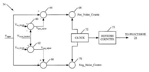
CA 02886533 2015-03-27
WO 2014/052232 PCT/US2013/061170
-6-
[0026]
Prior to describing the operation illustrated in FIG. 5, the elements of FIG.
4 will first
be briefly discussed. Vinput in FIG. 4 is the input voltage developed across
sensor 18 (in FIG. 3)
and applied between leads 40 and 42. Vinput_latched is the voltage across
capacitor C 1 (again in
FIG. 3) when switch S1 is closed. Vos_thõsh is a voltage set point that is
used by positive and
negative threshold generators 60 and 62 to generate positive and negative
thresholds (Vpos adjust
and Vneg adjust)= In the embodiment shown, the threshold generators are
comprised of a set of
summing nodes 60 and 62. Vinput_latched is added to noise threshold Vos_thresh
at summing node 60
and Vos_thõsh is subtracted from Vinput_latched at summing node 62. It should
also be noted that the
noise threshold Vos_thõsh can be determined empirically or it can vary from
implementation-to-
implementation. Similarly, two different thresholds could be used to generate
Vpos adjust and
Vneg adjust. In one embodiment, the value(s) of Vos thresh is set in firmware
or at manufacturing
time so the user need not set it or adjust it. Further, it can be adjustable
by the user and the
decision as to the particular threshold voltage can be made during
implementation. Also, the
threshold values can be variable based on a variety of different parameters,
such as the value of
the sensor signal, or other parameters.
[0027]
The resultant positive and negative threshold voltages (Vpos adjust and Vneg
adjust) are
provided to comparators 64 and 66 where they are compared with Vinput. The
output of
comparators 64 and 66 are provided to the input of counters 68 and 70,
respectively, which
receive a clock input from clock 72. When Vinput exceeds Vpos adjust in the
positive direction, and
when clock 72 provides a clock pulse, counter 68 will increment by one.
Similarly, when Vinput
exceeds Vneg adjust in the negative direction, and when clock 72 provides a
clock pulse to counter
70, then counter 70 will increment by one. In essence, during every clock
cycle of clock 72, the
output of comparators 64 and 66 are evaluated and noise registers (or
counters) 68 and 70 are
used to accumulate counts corresponding to both positive and negative noise
events if the
positive and negative noise threshold voltages (Vpos
and Vneg adjust) adjust are exceeded. Refresh
counter 73 is also clocked by clock 72 and provides a method to refresh Vinput
latch at a
predetermined rate. The refresh counter counts up to the refresh period where
it refreshes the
voltage latched across capacitor Cl at a refresh rate based on the output from
counter 73.
[0028]
The embodiment shown in FIG. 4 is only one illustrative embodiment, and others
could be used as well. For instance, in some applications only a single noise
counter can be used
CA 02886533 2015-03-27
WO 2014/052232 PCT/US2013/061170
-7-
and incremented with a positive noise event and decremented with a negative
noise event. This
could be used to characterize noise symmetry, for example.
[0029] With this explanation of FIG. 4, the overall operation of A/D
converter 22 in
detecting noise will now be described with respect to FIG. 5. FIGS. 3-5 will
be described in
conjunction with one another.
[0030] In one embodiment, before detecting noise, processor 24 provides a
reset signal to
counters 68 and 70, to reset the noise counters. This is indicated by block 80
in FIG. 5.
Processor 24 also illustratively resets refresh counter 73. This is indicated
by block 82 in FIG. 5.
[0031] Processor 24 then latches Vmput across capacitor Cl by closing
switch Sl. This is
indicated by block 84 in FIG. 5. Vinput can be latched across capacitor Cl at
some point in time
during which converter 32 is performing the analog-to-digital conversion on
Vmput. In one
embodiment, it is latched at the beginning of the conversion process, but it
can be refreshed
intermittently, as well. That is, processor 24 can open switch S1 and close it
again every X
number of counts output by refresh counter 73. The particular refresh rate can
be set empirically,
or adjusted based on a given application, or otherwise. It can be set in
firmware or at
manufacturing time, so the user need not set the refresh rate. Further, the
user can be provided
with the ability to reset the refresh rate, as desired.
[0032] In any case, once Vmput is latched across capacitor Cl, summing
nodes 60 and 62
generate the positive and negative threshold voltages Vpos adjust and Vneg
adjust which are applied to
comparators 64 and 66. As briefly mentioned above, when Vmput exceeds Vpos
adjust in the
positive direction, then counter 68 is incremented for each clock cycle of
clock 72. Similarly,
when Vinput exceeds the negative threshold Vneg adjust in the negative
direction, then counter 70 is
incremented for each clock cycle of clock 72. Testing the positive and
negative noise output and
incrementing counters 68 and 70, as needed, is indicated by block 86 in FIG.
5. After each clock
cycle, it is determined whether refresh counter 73 has reached a count value
that indicates that
the latched voltage Vinput latched should be refreshed. If so, processing
reverts to block 82 where
refresh counter 73 is set to zero. Making the determination of whether the
refresh counter is to
be reset is indicated by block 88 in FIG. 5.
[0033] If, at block 88 it is determined that the refresh counter need not
be reset yet, then
processor 24 determines whether converter 32 has completed its measurement of
Vinput. This is
CA 02886533 2015-03-27
WO 2014/052232 PCT/US2013/061170
-8-
indicated by block 90 in FIG. 5. If not, processing reverts back to block 86
where detector 34
continues to test the positive and negative noise outputs and increment
counters 68 and 70, as
needed.
[0034] However, if, at block 90, it is determined that the A/D conversion
has been
completed, then the counts 41 provided by counters 68 and 70 are output to
processor 24. This is
indicated by block 92 in FIG. 5. Processor 24, in turn, can characterize the
noise detected based
on the counts 41.
[0035] Processor 24 can then output the noise characteristics that it has
identified, based on
the counts 41 from counters 68 and 70. Outputting the noise characteristics is
indicated by block
94 in FIG. 5.
[0036] While there are a wide variety of different noise characteristics
that can be identified
by processor 24, based upon counts 41, a number of them will now be described
for the sake of
example only.
[0037] A first noise characteristic is referred to as noise symmetry. If
both the positive and
negative counters 68 and 70 provide counts that are equal, and those counts do
not exceed a
threshold value (i.e., they are not excessive), then processor 24 can
determine that the noise is
symmetric. This can provide an indication that the measurement output will be
impacted by the
measurement noise, but it allows processor 24 to provide an indication to the
user that a
degraded condition may exist. This type of noise can be induced by degrading
thermocouples in
a plant environment where noise currents are causing measurable voltages to be
developed on
higher impedance lines. This can inform the user that they are to provide
maintenance to their
sensor measurement loop, or other maintenance.
[0038] A second characteristic is reflective of noise frequency. That is,
processor 24 can
consider the refresh rate that defines the period that Vmput is latched across
capacitor Cl, and also
the quantity of counts output by counters 68 and 70. Given these parameters,
the approximate
noise frequency can be determined. If a new voltage level is latched
periodically within the
measurement process, but noise counts are still accumulated, this allows
processor 24 to
estimate, at least roughly, the quantity of noise that is in the given
measurement.
[0039] Yet another noise characteristic is the noise level. The noise level
can be estimated
by the quantity of counts output by counters 68 and 70, and the selected
voltage threshold level
CA 02886533 2015-03-27
WO 2014/052232 PCT/US2013/061170
-9-
Vos_thresh= The threshold level may be adjusted to provide information to
processor 24, and
ultimately to the user, as to how much noise exists in the system. This can be
important when
thermal electromotive forces (EMFs) are generated on RTD measurement lines. If
connection
points are corroded or frayed, and the temperature gradient exists across this
connection, a
dynamic EMF condition can be induced on the RTD measurement. In this case, the
user can be
made aware of this, so that they can perform maintenance on the measurement
loop. Processor
24 can generate a message that informs the user of this maintenance need.
[0040] Yet another noise characteristic is reflective of whether the
settling time is sufficient.
That is, if the measurement voltage Vinput is latched across capacitor C1 at
the beginning of the
digitization process performed by converter 32, and assuming there are a
relatively large number
of noise counts in the positive or negative direction (but not both), then
processor 24 can
determine that the settling time needs to be adjusted. After adjusting the
settling time, a new
measurement can be calculated. This process can help initialize settling time
for the connected
measurement loop to provide the highest level of accuracy with the best update
rate.
[0041] FIGS. 6-8 are plots of counters 68 and 70 along the x axis versus
voltage along the y
axis. FIGS. 6-8 illustrate some of the noise characteristics. In FIG. 6, Vmput
is indicated by line
100 and Vpos adjust is indicated by line 102, while Vueg adjust is indicated
by line 104. FIG. 6
illustrates what might be a reflection of normal measurement noise. That is,
Vmput varies well
within the thresholds established by threshold voltages 102 and 104. It can be
seen that the
output from counters 68 and 70 are both zero, because Vmput has not crossed
either threshold 102
or 104 during the measurement cycle.
[0042] FIG. 7 is similar to FIG. 6, and similar items are similarly
numbered. However, it can
be seen in FIG. 7 that Vmput 100 does cross the threshold voltages 102 and 104
by a certain
number of times. The positive count from counter 68 is 29 counts while the
negative count from
counter 70 is 25 counts. This indicates that the noise is slightly
asymmetrical in the positive
direction.
[0043] FIG. 8 is also similar to FIG. 6, and similar items are similarly
numbered. However,
FIG. 8 shows that, other than the very beginning of the measurement cycle,
Vmput is above
positive threshold 102 the entire time. Therefore, the positive counts output
by counter 68 are
CA 02886533 2015-03-27
WO 2014/052232 PCT/US2013/061170
-10-
380, while there are no negative counts. This tends to indicate that the
settling time is inaccurate
and needs to be adjusted.
[0044] Referring again to FIG. 5, having processor 24 output an indication
of noise
characteristics corresponding to noise symmetry is indicated by block 110.
Outputting a noise
characteristic corresponding to noise frequency is indicated by block 112,
while outputting an
indication as to noise level is indicated by block 114, and outputting an
indication that reflects a
settling time issue is indicated by block 116. Of course, processor 24 can
generate other outputs
118 as well, indicative of other noise characteristics.
[0045] It will be appreciated that processor 24, or other components of
transmitter 10, can
perform other actions as well based upon the counts output by counters 68 and
70. Performing
these other actions is indicated by block 120 in FIG. 5. For instance,
processor 24 can adjust the
settling time as indicated by block 122, or it can allow the user to adjust
the integration period
for the measurement cycle as indicated by block 124. Similarly, processor 24
can generate a
profile of the measurement system based on the noise characteristics
identified from counts 41
output by counters 68 and 70. This is indicated by block 126 in FIG. 5.
Generating a profile can
be done in a wide variety of ways. For instance, using a learning process,
such as statistical
process monitoring, processor 24 can generate a profile of the measurement
system which can be
referred to over time. This can help understand what noise level, refresh
rate, and settling time
should be used to configure each specific user installation. The noise level
at startup can be used
as a baseline for comparison of other measurement sample periods over time, as
well.
Transmitter 10, or other components can take a variety of other actions as
well, and this is
indicated by block 128 in FIG. 5.
[0046] Similarly, the counts can be used to detect line frequency that the
measurement loop
may be exposed to. For instance, in some user installations, a line frequency
(such as 50 Hz or
60 Hz) may be coupled to the measurement lines. In such an installation, a
user may be provided
with a settable parameter that allows the measurement to be integrated over
this period of time.
[0047] It will also be appreciated that a plurality of noise detection
components 26 can be
provided in a given transmitter 10. Each can be configured to process a
different noise
characteristic during the measurement cycle. For example, one noise detection
component 26
CA 02886533 2015-03-27
WO 2014/052232 PCT/US2013/061170
-11-
can be configured to specifically identify settling time issues, while another
can focus on noise
frequency and yet another on noise level, etc.
[0048] In addition, noise detection component 26 can be used to
continuously monitor the
noise on each of a plurality of different sensors, independently, even when a
given sensor output
is not currently being measured by transmitter 10. FIG. 9 shows such an
embodiment, which is
similar to that shown in FIG. 2, except that a second sensor 19 is shown as
well. Of course, a
plurality of additional sensors can be provided and FIG. 9 shows only two
sensors for the sake of
example. In the embodiment in FIG. 9, it may be that transmitter 10 receives
one sensor input at
a time through a multiplexor. Thus it may be that transmitter 10 is not
measuring the output of
sensor 18 because it is measuring the output of sensor 19. In that case,
however, noise detection
component 27 is still detecting the noise on the output of sensor 18.
Therefore, while noise
detection component 26 is detecting the noise on the sensor 19 that is
currently being measured
by converter 22, the noise on the output of sensor 18 is also being detected
by noise detection
component 27, because detecting noise on the output of a sensor when it is not
being measured
can be meaningful and helpful as well. This embodiment can also allow the
system to
characterize noise differences among the different sensors.
[0049] The system can also help to accurately compensate for the sensed
noise. Once the
noise is characterized, compensation becomes more accurate. Further, the clock
signal used to
clock the counters can be controlled to obtain more information. If the clock
frequency is
increased, higher frequency noise components can be detected. Therefore, the
clock frequency
can be controlled as desired.
[0050] Although the present invention has been described with reference to
preferred
embodiments, workers skilled in the art will recognize that changes may be
made in form and
detail without departing from the spirit and scope of the invention.