Note: Descriptions are shown in the official language in which they were submitted.
CA 02886563 2015-03-27
WO 2014/055287
PCT/US2013/061341
FLOW THROUGH GAUGE FOR DRILL BIT
RELATED APPLICATIONS
[0001] The present application is a non-provisional application of and
claims
priority under 35 U.S.C. 119 to U.S. Provisional Application No. 61/709,063,
entitled "Flow Through Gauge For Drill Bit" and filed on October 2, 2012, the
entirety of which is incorporated by reference herein.
[0002] The present application is related to U.S. Non-Provisional Patent
Application No. 14/034653, entitled "Blade Flow PDC Bits" and filed on
September
24, 2013, and U.S. Non-Provisional Patent Application No. 14/034733, entitled
"Machined High Angle Nozzle Sockets For Steel Body Bits" and filed on
September
24, 2013, both of which are hereby incorporated by reference herein.
BACKGROUND
[0003] This invention relates generally to drill bits and/or other
downhole
tools. More particularly, this invention relates to drill bits that include
one or more
flow management channels formed within one or more gauge sections of the drill
bits
and/or other downhole tools.
[0004] Figure 1 shows a perspective view of a drill bit 100 in
accordance with
the prior art. Referring to Figure 1, the drill bit 100 includes a bit body
110 that is
coupled to a shank 115 and is designed to rotate in a counter-clockwise
direction 190.
The shank 115 includes a threaded connection 116 at one end 120. The threaded
connection 116 couples to a drill string (not shown) or some other equipment
that is
coupled to the drill string. The threaded connection 116 is shown to be
positioned on
the exterior surface of the one end 120. This positioning assumes that the
drill bit 100
is coupled to a corresponding threaded connection located on the interior
surface of a
drill string (not shown). However, the threaded connection 116 at the one end
120 is
alternatively positioned on the interior surface of the one end 120 if the
corresponding
threaded connection of the drill string (not shown) is positioned on its
exterior surface
in other exemplary embodiments. A bore (not shown) is formed longitudinally
through the shank 115 and the bit body 110 for communicating drilling fluid
from
within the drill string to a drill bit face 111 via one or more nozzles 114
during
drilling operations.
- 1 -
CA 02886563 2015-03-27
WO 2014/055287
PCT/US2013/061341
[0005] The bit body 110 includes a plurality of gauge sections 150 and a
plurality of blades 130 extending from the drill bit face 111 of the bit body
110
towards the threaded connection 116, where each blade 130 extends to and
terminates
at a respective gauge section 150. The blade 130 and the respective gauge
section 150
are formed as a single component, but are formed separately in certain drill
bits 100.
The drill bit face 111 is positioned at one end of the bit body 110 furthest
away from
the shank 115. The plurality of blades 130 form the cutting surface of the
drill bit
100. One or more of these plurality of blades 130 are either coupled to the
bit body
110 or are integrally formed with the bit body 110. The gauge sections 150 are
positioned at an end of the bit body 110 adjacent the shank 115. The gauge
section
150 includes one or more gauge cutters (not shown) in certain drill bits 100.
The
gauge sections 150 typically define and hold the full hole diameter of the
drilled hole.
Each of the blades 130 and gauge sections 150 include a leading edge section
152, a
face section 154, and a trailing edge section 156. The face section 154
extends from
one end of the trailing edge section 156 to an end of the leading edge section
152.
The leading edge section 152 faces in the direction of rotation 190, while the
trailing
edge faces in the opposite direction of rotation 190. A junk slot 122 is
formed
between each consecutive blade 130, which allows for cuttings and drilling
fluid to
return to the surface of the wellbore (not shown) once the drilling fluid is
discharged
from the nozzles 114. A plurality of cutters 140 are coupled to each of the
blades 130
and extend outwardly from the surface of the blades 130 to cut through earth
formations when the drill bit 100 is rotated during drilling. One type of
cutter 140
used within the drill bit 100 is a PDC cutter; however other types of cutters
are
contemplated as being used within the drill bit 100. The cutters 140 and
portions of
the bit body 110 deform the earth formation by scraping and/or shearing
depending
upon the type of drill bit 100. Although one embodiment of the drill bit has
been
described, other drill bit embodiments or other downhole tools that include
one or
more gauge sections, which are known to people having ordinary skill in the
art, are
applicable to exemplary embodiments of the present invention.
[0006] During drilling of a borehole, the drill bit 100 rotates to cut
through an
earth formation to form a wellbore therein. This cutting is typically
performed
through scraping and/or shearing action according to certain drill bits 100,
but is
performed through other means based upon the type of drill bit used. Drilling
fluid
(not shown) exits the drill bit 100 through one or more nozzles 114 and
facilitates the
- 2 -
CA 02886563 2015-03-27
WO 2014/055287
PCT/US2013/061341
removal of the cuttings from the borehole wall back towards the surface. As
the drill
bit 110 rotates and the drilling fluid with cuttings are at the bottom of the
borehole,
the gauge section 150 is eroded rapidly, which also causes the surface of the
gauge
section 150 to become rounded. Further, the cuttings are re-grinded, which
thereby
generated additional heat and reduces the cooling function performed by the
drilling
fluid on the blades 130 and on the gauge section 150.
[0007] Gauge pad wear is a primary limiter of drill bit life. Cuttings
regrinding, caused by cuttings getting squeezed into the small gap that can
open up
during drilling between the gauge pad and the borehole wall, acts to
significantly
increase cuttings regrinding and wear. In standard smooth gauge pad design,
the
faces of the gauge pads constitute a hydraulic "dead zone" limiting hydraulic
cooling
and accelerating thermal induced deterioration of the gauge pad surfaces.
BRIEF DESCRIPTION OF THE DRAWINGS
[0008] The foregoing and other features and aspects of the invention
will be
best understood with reference to the following description of certain
exemplary
embodiments of the invention, when read in conjunction with the accompanying
drawings, wherein:
[0009] Figure 1 shows a perspective view of a drill bit in accordance
with the
prior art;
[0010] Figure 2 shows a perspective view of a drill bit including one or
more
flow channels in a gauge section of the drill bit in accordance with an
exemplary
embodiment of the present invention;
[0011] Figure 3 shows a schematic view of the one or more flow channels
in
the gauge section of the drill bit of Figure 2 in accordance with an exemplary
embodiment of the present invention;
[0012] Figure 4 shows a perspective view of a drill bit including one or
more
flow channels in a gauge section of the drill bit in accordance with an
exemplary
embodiment of the present invention;
[0013] Figure 5 shows a schematic view of the one or more flow channels
in
the gauge section of the drill bit of Figure 4 in accordance with an exemplary
embodiment of the present invention;
- 3 -
CA 02886563 2015-03-27
WO 2014/055287
PCT/US2013/061341
[0014] Figure 6 shows a perspective view of a drill bit including one or
more
flow channels in a gauge section of the drill bit in accordance with an
exemplary
embodiment of the present invention;
[0015] Figure 7 shows a schematic view of the one or more flow channels
in
the gauge section of the drill bit of Figure 6 in accordance with an exemplary
embodiment of the present invention;
[0016] Figure 8 shows a perspective view of a drill bit including one or
more
flow channels in a gauge section of the drill bit in accordance with an
exemplary
embodiment of the present invention;
[0017] Figure 9 shows a schematic view of the one or more flow channels
in
the gauge section of the drill bit of Figure 8 in accordance with an exemplary
embodiment of the present invention;
[0018] Figure 10 shows a perspective view of a drill bit including one
or more
flow channels in a gauge section of the drill bit in accordance with an
exemplary
embodiment of the present invention;
[0019] Figure 11 shows a schematic view of the one or more flow channels
in
the gauge section of the drill bit of Figure 10 in accordance with an
exemplary
embodiment of the present invention;
[0020] Figure 12 shows a perspective view of a drill bit including one
or more
flow channels in a gauge section of the drill bit in accordance with an
exemplary
embodiment of the present invention;
[0021] Figure 13 shows a schematic view of the one or more flow channels
in
the gauge section of the drill bit of Figure 12 in accordance with an
exemplary
embodiment of the present invention;
[0022] Figure 14 shows a perspective view of a drill bit including one
or more
flow channels in a gauge section of the drill bit in accordance with an
exemplary
embodiment of the present invention;
[0023] Figure 15 shows a schematic view of the one or more flow channels
in
the gauge section of the drill bit of Figure 14 in accordance with an
exemplary
embodiment of the present invention;
[0024] Figure 16 shows a perspective view of a drill bit including one
or more
flow channels in a gauge section of the drill bit in accordance with an
exemplary
embodiment of the present invention;
- 4 -
CA 02886563 2015-03-27
WO 2014/055287
PCT/US2013/061341
[0025] Figure 17 shows a schematic view of the one or more flow channels
in
the gauge section of the drill bit of Figure 16 in accordance with an
exemplary
embodiment of the present invention;
[0026] Figure 18 shows a perspective view of a drill bit including one
or more
flow channels in a gauge section of the drill bit in accordance with an
exemplary
embodiment of the present invention; and
[0027] Figure 19 shows a schematic view of the one or more flow channels
in
the gauge section of the drill bit of Figure 18 in accordance with an
exemplary
embodiment of the present invention.
[0028] The drawings illustrate only exemplary embodiments of the
invention
and are therefore not to be considered limiting of its scope, as the invention
may
admit to other equally effective embodiments.
DETAILED DESCRIPTION OF THE INVENTION
[0029] This invention relates generally to drill bits and/or other
downhole
tools. More particularly, this invention relates to drill bits that include
one or more
flow management channels formed within one or more gauge sections of the drill
bits
and/or other downhole tools. Although the description provided below is
related to a
fixed cutter bit, exemplary embodiments of the invention relate to any
downhole tool
having one or more gauge sections, such as, but not limited to, steel body or
matrix
PDC bits, impregnated bits, and other fixed cutter bits.
[0030] According to exemplary embodiments of the present invention, one
or
more inlet holes are deployed on a leading edge section adjacent to a gauge
section of
a bit. Further one or more outlet holes are deployed on one or more of the
face
section and/or a trailing edge section, where one or more outlet holes are
fluidly
coupled to at least one inlet hole. The outlet hole and the corresponding
inlet hole
form a fluid channel extending therebetween. The fluid channels are deployed
to
allow fluid to flow beneath at least a portion of the face section of the
gauge section to
provide cooling to the face section. Alternatively, the fluid channels are
deployed to
allow fluid to flow along at least a portion of the face section of the gauge
section,
also providing cooling to the face section. These fluid channels are deployed
at an
upward angle, in certain exemplary embodiments, to facilitate the movement of
entrained cuttings and drilling fluid in the uphole direction. However, in
other
- 5 -
CA 02886563 2015-03-27
WO 2014/055287
PCT/US2013/061341
exemplary embodiments, one or more fluid channels are deployed in a horizontal
direction or a downward angle.
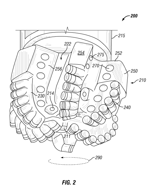
[0031] Figure 2 shows a perspective view of a drill bit 200 including
one or
more flow channels 360 in a gauge section 250 of the drill bit 200 in
accordance with
an exemplary embodiment of the present invention. Figure 3 shows a schematic
view
of the one or more flow channels 360 in the gauge section 250 of the drill bit
200 in
accordance with an exemplary embodiment of the present invention. Referring to
Figures 2 and 3, the drill bit 200 is similar to drill bit 100 (Figure 1) and
includes a bit
body 210 that is coupled to a shank 215. The drill bit 200 is designed to
rotate in a
counter-clockwise direction 290. The shank 215 includes a threaded connection
(not
shown) at one end (not shown). This threaded connection is similar to threaded
connection 116 (Figure 1). The threaded connection couples to a drill string
(not
shown) or some other equipment that is coupled to the drill string. A bore
(not
shown) is formed longitudinally through the shank and the bit body 210 for
communicating drilling fluid from within the drill string to a drill bit face
211 via one
or more nozzles 214 during drilling operations.
[0032] The bit body 210 includes a plurality of gauge sections 250 and a
plurality of blades 230 extending from the drill bit face 211 of the bit body
210
towards the shank 215, where each blade 230 extends to and terminates at a
respective
gauge section 250. The blade 230 and the respective gauge section 250 are
formed as
a single component, but are formed separately in other drill bits. The drill
bit face 211
is positioned at one end of the bit body 210 furthest away from the shank 215.
The
plurality of blades 230 form the cutting surface of the drill bit 200. One or
more of
these plurality of blades 230 are either coupled to the bit body 210 or are
integrally
formed with the bit body 210. The gauge sections 250 are positioned at an end
of the
bit body 210 adjacent the shank 215. The gauge section 250 includes one or
more
gauge cutters (not shown) in certain exemplary embodiments of drill bits. The
gauge
sections 250 typically define and hold the full hole diameter of the drilled
hole. Each
of the blades 230 and gauge sections 250 include a leading edge section 252, a
face
section 254, and a trailing edge section 256. The face section 254 extends
from one
end of the trailing edge section 256 to an end of the leading edge section 252
and
forms a front surface of the gauge section 250. The leading edge section 252
faces in
the direction of rotation 290, while the trailing edge section 256 faces in
the opposite
direction of rotation 290. A junk slot 222 is formed between each consecutive
blade
- 6 -
CA 02886563 2015-03-27
WO 2014/055287
PCT/US2013/061341
230, which allows for cuttings and drilling fluid to return to the surface of
the
wellbore (not shown) once the drilling fluid is discharged from the nozzles
214. A
plurality of cutters 240 are coupled to each of the blades 230 and extend
outwardly
from the surface of the blades 230 to cut through earth formations when the
drill bit
200 is rotated during drilling. One type of cutter 240 used within the drill
bit 200 is a
PDC cutter; however, other types of cutters are contemplated as being used
within the
drill bit 200. The cutters 240 and portions of the bit body 210 deform the
earth
formation by scraping and/or shearing depending upon the type of drill bit
200.
[0033] According to some exemplary embodiments, as shown in Figures 2
and 3, one or more inlet holes 270 are formed within the leading edge section
252 and
one or more outlet holes 275 are formed within the trailing edge section 256.
The
flow channel 360 extends from an inlet hole 270 to at least one corresponding
outlet
hole 275. Hence, the drilling fluid and/or cuttings enter into the flow
channel 360
through the inlet hole 270 and exits through the outlet hole 275. The fluid
flowing
through this flow channel 360 facilitates cooling of the gauge section 250 and
also
reduces erosion of the gauge section 250. In some exemplary embodiments, one
inlet
hole 270 corresponds to a single outlet hole 275. However, in other exemplary
embodiments, one inlet hole 270 corresponds and is fluidly communicable to a
plurality of outlet holes 275. Also, in certain exemplary embodiments, one or
more
outlet holes 275 is shaped and/or dimensioned differently than the
corresponding inlet
hole 270. For example, the outlet hole 275 is sized larger, in perimeter or
diameter,
than the corresponding inlet hole 270. This feature reduces plugging within
the flow
channel 360. In certain exemplary embodiments, at least one flow channel 360
is
directed in an upward angle from the inlet hole 270 to the outlet hole 275. In
other
exemplary embodiments, the flow channel 360 is directed substantially
horizontally
or in a downward direction towards the bottom of the borehole (not shown).
Hence,
in this exemplary embodiment, the fluid flow within the flow channel 360 is
beneath
the face section 254.
[0034] Figure 4 shows a perspective view of a drill bit 400 including
one or
more flow channels 560 in a gauge section 450 of the drill bit 400 in
accordance with
an exemplary embodiment of the present invention. Figure 5 shows a schematic
view
of the one or more flow channels 560 in the gauge section 450 of the drill bit
400 in
accordance with an exemplary embodiment of the present invention. Referring to
Figures 4 and 5, the drill bit 400 is similar to drill bit 200 (Figure 2).
However, gauge
- 7 -
CA 02886563 2015-03-27
WO 2014/055287
PCT/US2013/061341
section 450 is different from gauge section 250 (Figure 2) in that the flow
channel 560
is different than the flow channel 360 (Figure 3). Each of the gauge sections
450 and
blades 230, as described above with respect to drill bit 200 (Figure 2),
include a
leading edge section 452, a face section 454, and a trailing edge section 456.
The face
section 454 extends from one end of the trailing edge section 456 to an end of
the
leading edge section 452 and forms a front surface of the gauge section 450.
The
leading edge section 452 faces in the direction of rotation 490 of the drill
bit 400,
while the trailing edge section 456 faces in the opposite direction of
rotation 490.
[0035] According to some exemplary embodiments, as shown in Figures 4
and 5, one or more inlet holes 470 are formed within the leading edge section
452 and
one or more outlet holes 475 are formed within the face section 454. The flow
channel 560 extends from an inlet hole 470 to at least one corresponding
outlet hole
475. Hence, the drilling fluid and/or cuttings enter into the flow channel 560
through
the inlet hole 470 and exits through the outlet hole 475. The fluid flowing
through
this flow channel 560 facilitates cooling of the gauge section 450 and also
reduces
erosion of the gauge section 450. In some exemplary embodiments, one inlet
hole
470 corresponds to and is in fluid communication with a single outlet hole
475.
However, in other exemplary embodiments, one inlet hole 470 corresponds to and
is
in fluid communication with a plurality of outlet holes 475. Also, in certain
exemplary embodiments, one or more outlet holes 475 is shaped and/or
dimensioned
differently than the corresponding inlet hole 470. For example, the outlet
hole 475 is
sized larger, in perimeter or diameter, than the corresponding inlet hole 470.
This
feature reduces plugging within the flow channel 560. In certain exemplary
embodiments, at least one flow channel 560 is directed in an upward angle from
the
inlet hole 470 to the outlet hole 475. In other exemplary embodiments, the
flow
channel 560 is directed substantially horizontally or in a downward direction
towards
the bottom of the borehole (not shown).
[0036] Figure 6 shows a perspective view of a drill bit 600 including
one or
more flow channels 760 in a gauge section 650 of the drill bit 600 in
accordance with
an exemplary embodiment of the present invention. Figure 7 shows a schematic
view
of the one or more flow channels 760 in the gauge section 650 of the drill bit
600 in
accordance with an exemplary embodiment of the present invention. Referring to
Figures 6 and 7, the drill bit 600 is similar to drill bit 200 (Figure 2).
However, gauge
section 650 is different from gauge section 250 (Figure 2) in that the flow
channel 760
- 8 -
CA 02886563 2015-03-27
WO 2014/055287
PCT/US2013/061341
is different than the flow channel 360 (Figure 3). Each of the gauge sections
650 and
blades 230, as described above with respect to drill bit 200 (Figure 2),
include a
leading edge section 652, a face section 654, and a trailing edge section 656.
The face
section 654 extends from one end of the trailing edge section 656 to an end of
the
leading edge section 652 and forms a front surface of the gauge section 650.
The
leading edge section 652 faces in the direction of rotation 690 of the drill
bit 600,
while the trailing edge section 656 faces in the opposite direction of
rotation 690.
[0037] According to some exemplary embodiments, as shown in Figures 6
and 7, one or more inlet holes 670 are formed within the leading edge section
652 and
one or more outlet holes 675 are formed within the face section 654. Further,
a deep
groove 678 is formed within the face section 654 extending from the one or
more
outlet holes 675 to the trailing edge section 656. The deep groove 678 is
substantially
trapezoidal shaped in some exemplary embodiments; however, in other exemplary
embodiments, the deep groove 678 is formed in any other geometric shape, such
as
rectangular or triangular, or non-geometric shape. The deep groove 678 is
about 3/4"
deep in some exemplary embodiments but is greater in depth in other exemplary
embodiments. However, according to certain exemplary embodiments, deep groove
678 is less than 1/4" deep. In some exemplary embodiments, the depth of the
deep
groove 678 is substantially constant throughout the deep groove 678; however,
the
depth varies in other exemplary embodiments. For example, the depth of the
deep
groove 678 is shallower near the outlet holes 675 and deeper near the trailing
edge
section 656. The flow channel 760 extends from an inlet hole 670 to at least
one
corresponding outlet hole 675. Hence, the drilling fluid and/or cuttings enter
into the
flow channel 760 through the inlet hole 670 and exits through the outlet hole
675.
The fluid flowing through this flow channel 760 facilitates cooling of the
gauge
section 650 and also reduces erosion of the gauge section 650. In some
exemplary
embodiments, one inlet hole 670 corresponds to and is in fluid communication
with a
single outlet hole 675. However, in other exemplary embodiments, one inlet
hole 670
corresponds to and is in fluid communication with a plurality of outlet holes
675.
Also, in certain exemplary embodiments, one or more outlet holes 675 is shaped
and/or dimensioned differently than the corresponding inlet hole 670. For
example,
the outlet hole 675 is sized larger, in perimeter or diameter, than the
corresponding
inlet hole 670. This feature reduces plugging within the flow channel 760. In
certain
exemplary embodiments, at least one flow channel 760 is directed in an upward
angle
- 9 -
CA 02886563 2015-03-27
WO 2014/055287
PCT/US2013/061341
from the inlet hole 670 to the outlet hole 675. In other exemplary
embodiments, the
flow channel 760 is directed substantially horizontally or in a downward
direction
towards the bottom of the borehole (not shown).
[0038] Figure 8 shows a perspective view of a drill bit 800 including
one or
more flow channels 960 in a gauge section 850 of the drill bit 800 in
accordance with
an exemplary embodiment of the present invention. Figure 9 shows a schematic
view
of the one or more flow channels 960 in the gauge section 850 of the drill bit
800 in
accordance with an exemplary embodiment of the present invention. Referring to
Figures 8 and 9, the drill bit 800 is similar to drill bit 200 (Figure 2).
However, gauge
section 850 is different from gauge section 250 (Figure 2) in that the flow
channel 960
is different than the flow channel 360 (Figure 3). Each of the gauge sections
850 and
blades 230, as described above with respect to drill bit 200 (Figure 2),
include a
leading edge section 852, a face section 854, and a trailing edge section 856.
The face
section 854 extends from one end of the trailing edge section 856 to an end of
the
leading edge section 852 and forms a front surface of the gauge section 850.
The
leading edge section 852 faces in the direction of rotation 890 of the drill
bit 800,
while the trailing edge section 856 faces in the opposite direction of
rotation 890.
[0039] According to some exemplary embodiments, as shown in Figures 8
and 9, one or more inlet holes 870 are formed within the leading edge section
852 and
one or more outlet holes 875 are formed within both the face section 854 and
the
trailing edge section 856. The flow channel 960 extends from an inlet hole 870
to
corresponding outlet holes 875, at least one formed in the face section 854
and at least
one formed in the trailing edge section 856. Hence, the drilling fluid and/or
cuttings
enter into the flow channel 960 through the inlet hole 870 and exits through
each of
the corresponding outlet holes 875, one of which is positioned on the face
section 854
and one of which is positioned on the trailing edge section 856. The fluid
flowing
through this flow channel 960 facilitates cooling of the gauge section 850 and
also
reduces erosion of the gauge section 850. In some exemplary embodiments, one
inlet
hole 870 corresponds to and is in fluid communication with a single outlet
hole 875
on the face section 854 and a single outlet hole 875 on the trailing edge
section 856.
However, in other exemplary embodiments, one inlet hole 870 corresponds to and
is
in fluid communication with one outlet hole 875 on the face section 854, one
outlet
hole 875 on the trailing edge section 856, and at least one additional outlet
hole 875
on either or both of the face section 854 and the trailing edge section 856.
Also, in
- 10 -
CA 02886563 2015-03-27
WO 2014/055287
PCT/US2013/061341
certain exemplary embodiments, one or more outlet holes 875 is shaped and/or
dimensioned differently than the corresponding inlet hole 870. For example,
the
outlet hole 875 is sized larger, in perimeter or diameter, than the
corresponding inlet
hole 870. This feature reduces plugging within the flow channel 960. In
certain
exemplary embodiments, at least one flow channel 960 is directed in an upward
angle
from the inlet hole 870 to at least one outlet hole 875. In other exemplary
embodiments, at least one flow channel 960 is directed substantially
horizontally or in
a downward direction towards the bottom of the borehole (not shown).
[0040] Figure 10 shows a perspective view of a drill bit 1000 including
one or
more flow channels 1160 in a gauge section 1050 of the drill bit 1000 in
accordance
with an exemplary embodiment of the present invention. Figure 11 shows a
schematic view of the one or more flow channels 1160 in the gauge section
81050 of
the drill bit 1000 in accordance with an exemplary embodiment of the present
invention. Referring to Figures 10 and 11, the drill bit 1000 is similar to
drill bit 200
(Figure 2). However, gauge section 1050 is different from gauge section 250
(Figure
2) in that the flow channel 1160 is different than the flow channel 360
(Figure 3).
Each of the gauge sections 1050 and blades 230, as described above with
respect to
drill bit 200 (Figure 2), include a leading edge section 1052, a face section
1054, and
a trailing edge section 1056. The face section 1054 extends from one end of
the
trailing edge section 1056 to an end of the leading edge section 1052 and
forms a
front surface of the gauge section 1050. The leading edge section 1052 faces
in the
direction of rotation 1090 of the drill bit 1000, while the trailing edge
section 1056
faces in the opposite direction of rotation 1090.
[0041] According to some exemplary embodiments, as shown in Figures 10
and 11, one or more inlet holes 1070 are formed within the leading edge
section 1052
and one or more outlet holes 1075 are formed within both the face section 1054
and
the trailing edge section 1056. Further, a deep groove 1078 is formed within
the face
section 1054 extending from the one or more outlet holes 1075 formed in the
face
section 1054 to the trailing edge section 1056. The deep groove 1078 is
substantially
trapezoidal shaped in some exemplary embodiments; however, in other exemplary
embodiments, the deep groove 1078 is formed in any other geometric shape, such
as
rectangular or triangular, or non-geometric shape. The deep groove 1078 is
about 'A"
deep in some exemplary embodiments but is greater in depth in other exemplary
embodiments. However, according to certain exemplary embodiments, deep groove
- 11 -
CA 02886563 2015-03-27
WO 2014/055287
PCT/US2013/061341
1078 is less than 1/4" deep. In some exemplary embodiments, the depth of the
deep
groove 1078 is substantially constant throughout the deep groove 1078;
however, the
depth varies in other exemplary embodiments. For example, the depth of the
deep
groove 1078 is shallower near the outlet holes 1075 formed within the face
section
1054 and deeper near the trailing edge section 1056. The flow channel 1160
extends
from an inlet hole 1070 to corresponding outlet holes 1075, at least one
formed in the
face section 1054 and at least one formed in the trailing edge section 1056.
Hence,
the drilling fluid and/or cuttings enter into the flow channel 1160 through
the inlet
hole 1070 and exits through each of the corresponding outlet holes 1075, one
of
which is positioned on the face section 1054 and one of which is positioned on
the
trailing edge section 1056. The fluid flowing through this flow channel 1160
facilitates cooling of the gauge section 1050 and also reduces erosion of the
gauge
section 1050. In some exemplary embodiments, one inlet hole 1070 corresponds
to
and is in fluid communication with a single outlet hole 1075 on the face
section 1054
and a single outlet hole 1075 on the trailing edge section 1056. However, in
other
exemplary embodiments, one inlet hole 1070 corresponds to and is in fluid
communication with one outlet hole 1075 on the face section 1054, one outlet
hole
1075 on the trailing edge section 1056, and at least one additional outlet
hole 1075 on
either or both of the face section 1054 and the trailing edge section 1056.
Also, in
certain exemplary embodiments, one or more outlet holes 1075 is shaped and/or
dimensioned differently than the corresponding inlet hole 1070. For example,
the
outlet hole 1075 is sized larger, in perimeter or diameter, than the
corresponding inlet
hole 1070. This feature reduces plugging within the flow channel 1160. In
certain
exemplary embodiments, at least one flow channel 1160 is directed in an upward
angle from the inlet hole 1070 to at least one outlet hole 1075. In other
exemplary
embodiments, at least one flow channel 1160 is directed substantially
horizontally or
in a downward direction towards the bottom of the borehole (not shown).
[0042] Figure 12 shows a perspective view of a drill bit 1200 including
one or
more flow channels 1260 in a gauge section 1250 of the drill bit 1200 in
accordance
with an exemplary embodiment of the present invention. Figure 13 shows a
schematic view of the one or more flow channels 1260 in the gauge section 1250
of
the drill bit 1200 in accordance with an exemplary embodiment of the present
invention. Referring to Figures 12 and 13, the drill bit 1200 is similar to
drill bit 200
(Figure 2). However, gauge section 1250 is different from gauge section 250
(Figure
- 12 -
CA 02886563 2015-03-27
WO 2014/055287
PCT/US2013/061341
2) in that the flow channel 1260 is different than the flow channel 360
(Figure 3).
Each of the gauge sections 1250 and blades 230, as described above with
respect to
drill bit 200 (Figure 2), include a leading edge section 1252, a face section
1254, and
a trailing edge section 1256. The face section 1254 extends from one end of
the
trailing edge section 1256 to an end of the leading edge section 1252 and
forms a
front surface of the gauge section 1250. The leading edge section 1252 faces
in the
direction of rotation 1290 of the drill bit 1200, while the trailing edge
section 1256
faces in the opposite direction of rotation 1290.
[0043] According to some exemplary embodiments, as shown in Figures 12
and 13, one or more deep grooves 1278 are formed within the face section 1254
extending from the leading edge section 1252 to the trailing edge section
1256. The
deep groove 1278 is substantially hour-glass shaped in some exemplary
embodiments;
however, in other exemplary embodiments, the deep groove 1278 is formed in any
other geometric shape, such as rectangular, triangular, or inverted triangular
shapes,
or non-geometric shape. In some exemplary embodiments, the flow channel 1260
is
wider at the leading edge section 1252 and the trailing edge section 1256, but
narrower therebetween. Alternatively, the flow channel 1260 is narrower at the
leading edge section 1252 and wider at the trailing edge section 1256.
Further, in
other exemplary embodiments, the flow channel 1260 is wider at the leading
edge
section 1252 and narrower at the trailing edge section 1256. The deep groove
1278 is
about 3/4" deep in some exemplary embodiments but is greater in depth in other
exemplary embodiments. However, according to certain exemplary embodiments,
deep groove 1278 is less than 1/4" deep. In some exemplary embodiments, the
depth
of the deep groove 1278 is substantially constant throughout the deep groove
1278;
however, the depth varies in other exemplary embodiments. For example, the
depth
of the deep groove 1278 is shallower near the leading edge section 1252 and
deeper
near the trailing edge section 1256. The deep grooves 1278 is formed by
milling,
casting, or using any other known technique. The flow channel 1260, defined by
the
one or more deep grooves 1278, extends from the leading edge section 1252 to
the
trailing edge section 1256. Hence, the drilling fluid and/or cuttings enter
into the flow
channel 1260 through the leading edge section 1252 and exits through the
trailing
edge section 1256. The fluid flowing through this flow channel 1260
facilitates
cooling of the gauge section 1250 and also reduces erosion of the gauge
section 1250.
In certain exemplary embodiments, at least one flow channel 1260 is directed
in an
- 13 -
CA 02886563 2015-03-27
WO 2014/055287
PCT/US2013/061341
upward angle from the leading edge section 1252 to the trailing edge section
1256. In
other exemplary embodiments, the flow channel 1260 is directed substantially
horizontally or in a downward direction towards the bottom of the borehole
(not
shown). Here, the flow channel 1260 is disposed adjacently and along the face
section 1254.
[0044] Figure 14 shows a perspective view of a drill bit 1400 including
one or
more flow channels 1460 in a gauge section 1450 of the drill bit 1400 in
accordance
with an exemplary embodiment of the present invention. Figure 15 shows a
schematic view of the one or more flow channels 1460 in the gauge section 1450
of
the drill bit 1400 in accordance with an exemplary embodiment of the present
invention. Referring to Figures 14 and 15, the drill bit 1400 is similar to
drill bit 200
(Figure 2). However, gauge section 1450 is different from gauge section 250
(Figure
2) in that the flow channel 1460 is different than the flow channel 360
(Figure 3).
Each of the gauge sections 1450 and blades 230, as described above with
respect to
drill bit 200 (Figure 2), include a leading edge section 1452, a face section
1454, and
a trailing edge section 1456. The face section 1454 extends from one end of
the
trailing edge section 1456 to an end of the leading edge section 1452 and
forms a
front surface of the gauge section 1450. The leading edge section 1452 faces
in the
direction of rotation 1490 of the drill bit 1400, while the trailing edge
section 1456
faces in the opposite direction of rotation 1490.
[0045] According to some exemplary embodiments, as shown in Figures 14
and 15, one or more deep grooves 1478 are formed within the face section 1454
extending from the leading edge section 1452 to the trailing edge section
1456. The
deep groove 1478 is substantially any non-geometric shape and forms one or
more
pods 1479 in some exemplary embodiments; however, in other exemplary
embodiments, the deep groove 1478 is formed in any geometric shape still
forming
one or more pods 1479. The deep groove 1478 surrounds the pods 1479, or
islands.
In some exemplary embodiments, one or more pods 1479 are circular shaped, but
are
shaped into other geometric shape, such as oval, diamond, or square, or non-
geometric shapes in other exemplary embodiments. The deep groove 1478 is about
1/4" deep in some exemplary embodiments but is greater in depth in other
exemplary
embodiments. However, according to certain exemplary embodiments, deep groove
1478 is less than 3/4" deep. In some exemplary embodiments, the depth of the
deep
groove 1478 is substantially constant throughout the deep groove 1478;
however, the
- 14 -
CA 02886563 2015-03-27
WO 2014/055287
PCT/US2013/061341
depth varies in other exemplary embodiments. For example, the depth of the
deep
groove 1478 is shallower near the leading edge section 1452 and deeper near
the
trailing edge section 1456. The deep grooves 1478 is formed by milling,
casting, or
using any other known technique. The flow channel 1460, defined by the one or
more
deep grooves 1478, extends from the leading edge section 1452 to the trailing
edge
section 1456 and surrounds the one or more pods 1479. Hence, the drilling
fluid
and/or cuttings enter into the flow channel 1460 through the leading edge
section
1452, passes around the pods 1479, and exits through the trailing edge section
1456.
The fluid flowing through this flow channel 1460 facilitates cooling of the
gauge
section 1450 and also reduces erosion of the gauge section 1450. In certain
exemplary embodiments, at least one flow channel 1460 is directed in an upward
angle from the leading edge section 1452 to the trailing edge section 1456. In
other
exemplary embodiments, the flow channel 1460 is directed substantially
horizontally
or in a downward direction towards the bottom of the borehole (not shown).
Here, the
flow channel 1460 is disposed adjacently and along the face section 1454.
[0046] Figure 16 shows a perspective view of a drill bit 1600 including
one or
more flow channels 1660 in a gauge section 1650 of the drill bit 1600 in
accordance
with an exemplary embodiment of the present invention. Figure 17 shows a
schematic view of the one or more flow channels 1660 in the gauge section 1650
of
the drill bit 1600 in accordance with an exemplary embodiment of the present
invention. Referring to Figures 16 and 17, the drill bit 1600 is similar to
drill bit 200
(Figure 2). However, gauge section 1650 is different from gauge section 250
(Figure
2) in that the flow channel 1660 is different than the flow channel 360
(Figure 3).
Each of the gauge sections 1650 and blades 230, as described above with
respect to
drill bit 200 (Figure 2), include a leading edge section 1652, a face section
1654, and
a trailing edge section 1656. The face section 1654 extends from one end of
the
trailing edge section 1656 to an end of the leading edge section 1652 and
forms a
front surface of the gauge section 1650. The leading edge section 1652 faces
in the
direction of rotation 1690 of the drill bit 1600, while the trailing edge
section 1656
faces in the opposite direction of rotation 1690.
[0047] According to some exemplary embodiments, as shown in Figures 16
and 17, one or more deep grooves 1678 are formed within the face section 1654
extending from the leading edge section 1652 to the trailing edge section
1656. The
deep groove 1678 is substantially rectangularly shaped, or linearly, in some
- 15 -
CA 02886563 2015-03-27
WO 2014/055287
PCT/US2013/061341
exemplary embodiments; however, in other exemplary embodiments, the deep
groove
1678 is formed in any other geometric shape, such as curve-shaped, triangular
or
inverted triangular shapes, or non-geometric shape. In some exemplary
embodiments,
the flow channel 1660 is wider at the leading edge section 1652 and the
trailing edge
section 1656, but narrower therebetween. Alternatively, the flow channel 1660
is
narrower at the leading edge section 1652 and wider at the trailing edge
section 1656.
Further, in other exemplary embodiments, the flow channel 1660 is wider at the
leading edge section 1652 and narrower at the trailing edge section 1656. The
deep
groove 1678 is about 1/1" deep in some exemplary embodiments but is greater in
depth
in other exemplary embodiments. However, according to certain exemplary
embodiments, deep groove 1678 is less than IA" deep. In some exemplary
embodiments, the depth of the deep groove 1678 is substantially constant
throughout
the deep groove 1678; however, the depth varies in other exemplary
embodiments.
For example, the depth of the deep groove 1678 is shallower near the leading
edge
section 1652 and deeper near the trailing edge section 1656. The deep grooves
1678
is formed by milling, casting, or using any other known technique. The flow
channel
1660, defined by the one or more deep grooves 1678, extends from the leading
edge
section 1652 to the trailing edge section 1656. Hence, the drilling fluid
and/or
cuttings enter into the flow channel 1660 through the leading edge section
1652
and/or through the face section 1654 and exits through the trailing edge
section 1656.
The fluid flowing through this flow channel 1660 facilitates cooling of the
gauge
section 1650 and also reduces erosion of the gauge section 1650. In certain
exemplary embodiments, at least one flow channel 1660 is directed in an upward
angle from the leading edge section 1652 to the trailing edge section 1656. In
other
exemplary embodiments, the flow channel 1660 is directed substantially
horizontally
or in a downward direction towards the bottom of the borehole (not shown).
Here, the
flow channel 1660 is disposed adjacently and along the face section 1654.
According
to certain exemplary embodiments, none of the flow channels 1660 intersect
with
another flow channel 1660. However, in other exemplary embodiments, at least
one
flow channel 1660 intersects with at least one other flow channel 1660.
[0048] Figure 18 shows a perspective view of a drill bit 1800 including
one or
more flow channels 1860 in a gauge section 1850 of the drill bit 1800 in
accordance
with an exemplary embodiment of the present invention. Figure 19 shows a
schematic view of the one or more flow channels 1860 in the gauge section 1850
of
- 16 -
CA 02886563 2015-03-27
WO 2014/055287
PCT/US2013/061341
the drill bit 1800 in accordance with an exemplary embodiment of the present
invention. Referring to Figures 18 and 19, the drill bit 1800 is similar to
drill bit 200
(Figure 2). However, gauge section 1850 is different from gauge section 250
(Figure
2) in that the flow channel 1860 is different than the flow channel 360
(Figure 3).
Each of the gauge sections 1850 and blades 230, as described above with
respect to
drill bit 200 (Figure 2), include a leading edge section 1852, a face section
1854, and
a trailing edge section 1856. The face section 1854 extends from one end of
the
trailing edge section 1856 to an end of the leading edge section 1852 and
forms a
front surface of the gauge section 1850. The leading edge section 1852 faces
in the
direction of rotation 1890 of the drill bit 1800, while the trailing edge
section 1856
faces in the opposite direction of rotation 1890.
[0049] According to some exemplary embodiments, as shown in Figures 18
and 18, one or more deep grooves 1878 are formed within the face section 1854
extending from the leading edge section 1852 to the trailing edge section
1856. The
deep groove 1878 is substantially curved-shaped in some exemplary embodiments;
however, in other exemplary embodiments, the deep groove 1878 is formed in any
other geometric shape, such as linearly, triangular or inverted triangular
shapes, or
non-geometric shape. In some exemplary embodiments, the flow channel 1860 is
wider at the leading edge section 1852 and the trailing edge section 1856, but
narrower therebetween. Alternatively, the flow channel 1860 is narrower at the
leading edge section 1852 and wider at the trailing edge section 1856.
Further, in
other exemplary embodiments, the flow channel 1860 is wider at the leading
edge
section 1852 and narrower at the trailing edge section 1856. The deep groove
1878 is
about 3/4" deep in some exemplary embodiments but is greater in depth in other
exemplary embodiments. However, according to certain exemplary embodiments,
deep groove 1878 is less than 1/4" deep. In some exemplary embodiments, the
depth
of the deep groove 1878 is substantially constant throughout the deep groove
1878;
however, the depth varies in other exemplary embodiments. For example, the
depth
of the deep groove 1878 is shallower near the leading edge section 1852 and
deeper
near the trailing edge section 1856. The deep grooves 1878 is formed by
milling,
casting, or using any other known technique. The flow channel 1860, defined by
the
one or more deep grooves 1878, extends from the leading edge section 1852 to
the
trailing edge section 1856. Hence, the drilling fluid and/or cuttings enter
into the flow
channel 1860 through the leading edge section 1852 and/or through the face
section
- 17 -
CA 02886563 2015-03-27
WO 2014/055287
PCT/US2013/061341
1854 and exits through the trailing edge section 1856. The fluid flowing
through this
flow channel 1860 facilitates cooling of the gauge section 1850 and also
reduces
erosion of the gauge section 1850. In certain exemplary embodiments, at least
one
flow channel 1860 is directed in an upward angle from the leading edge section
1852
to the trailing edge section 1856. In other exemplary embodiments, the flow
channel
1860 is directed substantially horizontally or in a downward direction towards
the
bottom of the borehole (not shown). Here, the flow channel 1860 is disposed
adjacently and along the face section 1854. According to certain exemplary
embodiments, none of the flow channels 1860 intersect with another flow
channel
1860. However, in other exemplary embodiments, at least one flow channel 1860
intersects with at least one other flow channel 1860.
[0050] In some of the above exemplary embodiments, the flow channel is
linear when extending from the leading edge section to the trailing edge
section and
curved when extending from the leading edge section to the face section.
However,
the flow channel is linear or curved regardless of the endpoint of the flow
channel in
other exemplary embodiments. Some drill bits and/or downhole tools include
flow
channels that are of a combination of any of the above mentioned flow
channels.
Although not specifically recited in each of the exemplary embodiments, any
feature
of one of the exemplary embodiments described above is combinable with any
other
exemplary embodiment to form a different exemplary embodiment, which is
contemplated to be included as another exemplary embodiment of the present
invention.
[0051] Exemplary embodiments of this invention also are combinable with
one or more "High Angle Nozzle" feature as disclosed, or similarly disclosed,
within
U.S. Non-Provisional Patent Application No. 14/034733, entitled "Machined High
Angle Nozzle Sockets For Steel Body Bits" and filed on September 24, 2013,
and/or
one or more "Flow Through" blade features as disclosed within U.S. Non-
Provisional
Patent Application No. 14/034653, entitled "Blade Flow PDC Bits" and filed on
September 24, 2013, both of which have previously been hereby incorporated by
reference herein.
[0052] Although the invention has been described with reference to
specific
embodiments, these descriptions are not meant to be construed in a limiting
sense.
Various modifications of the disclosed embodiments, as well as alternative
embodiments of the invention will become apparent to persons skilled in the
art upon
- 18 -
CA 02886563 2015-03-27
WO 2014/055287
PCT/US2013/061341
reference to the description of the invention. It should be appreciated by
those skilled
in the art that the conception and the specific embodiments disclosed may be
readily
utilized as a basis for modifying or designing other structures for carrying
out the
same purposes of the invention. It should also be realized by those skilled in
the art
that such equivalent constructions do not depart from the spirit and scope of
the
invention as set forth in the appended claims. It is therefore, contemplated
that the
claims will cover any such modifications or embodiments that fall within the
scope of
the invention.
- 19 -