Note: Descriptions are shown in the official language in which they were submitted.
CA 02886590 2015-03-31
Vehicle Roof-Top Tent
FIELD OF INVENTION
[0001] The present invention relates tents, and in particular, relates to
various features and
accessories for vehicle roof-top tents.
BACKGROUND OF THE INVENTION
[0002] Camping has been a popular recreation for many years. Although camper
vans and
motor homes are commonly used by campers, they are expensive and they do not
allow the
campers to enjoy a close experience with nature to the extent that canvas and
fabric tents do.
However, canvas and fabric tents are typically placed on the ground, exposing
them to
problems with dampness, puddles, mud, rocky or uneven ground, insects, small
mammals and
other pests. Larger mammals such as bears, are downright dangerous for campers
in tents
placed on the ground. As a result, many attempts have been made to offer tents
which are
elevated, being mounted for example, on the tops of cars, SUVs and vans, or in
the beds of
trucks.
[0003] But the current offerings of vehicle-mounted tents still have many
undesirable features
such as weight, bulkiness, slow and/or complicated set-up, lack of aesthetic
or convenient
features, and many loose parts to be stored.
[0004] There is therefore a need for an improved vehicle-mounted tent and
accessories.
SUMMARY OF THE INVENTION
[0005] It is an object of the invention to provide an improved vehicle-mounted
tent and
accessories.
[0006] According to one aspect of the present invention there is provided a
vehicle roof-
mounted tent comprising a base including: a fixed portion for mounting on the
roof of the
vehicle and a pivoting portion connected to the fixed portion, the pivoting
portion being
CA 02886590 2015-03-31
arranged to pivot away from the vehicle. The tent also comprises a main tent
portion,
generally of tent fabric, including a pivoting frame, the main tent portion
being positioned
over the fixed and pivotal portions of the base; and a canopy portion,
generally of tent fabric,
extending beyond the end of the pivoting portion of the base.
[0007] According to another aspect of the present invention there is provided
a tent for
mounting on the roof of a vehicle comprising: a base including a fixed portion
for mounting
on the roof of the vehicle and a pivoting portion connected to the fixed
portion, the pivoting
portion being arranged to pivot away from the vehicle. The tent also comprises
a main tent
portion of tent fabric, including: a pivoting frame; a door; and at least one
window on a roof
surface to serve as a skylight; the main tent portion being positioned over
the fixed and
pivotal portions of the base; a canopy portion of tent fabric, extending
beyond the end of the
pivoting portion of the base; a rain fly, comprising a PVC window positioned
above the
window on the roof surface of the main tent, the rain fly being positioned
over the main tent
portion and the canopy portion; and an access ladder pivotally connected to
the end of the
pivoting portion of the base.
[0008] As explained herein after, the claimed inventions provide many
advantages over tents
in the prior art. For example, the roof-top design frees up space inside your
vehicle, and
height provides a defense against wildlife and ground-related elements. Other
advantageous
aspects of the claimed inventions include a superior curved frame, removable
shoe/utility
bags, a roll-up window awning, large semicircular windows, a canopy PVC
window,
aluminum honeycomb tent base, an advantageous stowing arrangement for the
canopy pole,
bungee cord pockets, dual PVC skylights and a quick release mounting for the
vehicle roof
rack.
[0009] Other systems, methods, features and advantages of the invention will
be, or will
become, apparent to one with skill in the art upon examination of the
following figures and
detailed description. It is intended that all such additional systems,
methods, features and
2
CA 02886590 2015-03-31
advantages be included within this description, be within the scope of the
invention, and be
protected by the following claims.
BRIEF DESCRIPTION OF THE DRAWINGS
[0010] These and other features of the invention will become more apparent
from the
following description in which reference is made to the appended drawings
wherein:
[0011] FIGURE 1 shows a front perspective view of a tent in accordance with an
embodiment
of the present invention, having dual sky lights, in the deployed position on
the roof of a
vehicle, with the rain fly installed and the front awning deployed.
[0012] FIGURE 2 shows a front view of the arrangement of Figure 1, in
accordance with an
embodiment of the present invention.
[0013] FIGURE 3 shows a perspective view of the arrangement of Figure 1, in
accordance
with an embodiment of the present invention, from the rear, canopy side and
below.
[0014] FIGURE 4 shows a perspective view of the interior frame and base
portions of a tent
in accordance with an embodiment of the present invention.
[0015] FIGURE 5 shows a detailed view of one of the pairs of brackets in
accordance with an
embodiment of the present invention.
[0016] FIGURES 6 and 7 show perspective views of a socket to support the
canopy pole, in
accordance with an embodiment of the present invention.
[0017] FIGURE 8 shows a top perspective view of the tent with the pivoting
portion of the
base in the stowed position, the ladder in the contracted and stowed position,
and the canopy
pole in a stowed position, in accordance with an embodiment of the present
invention.
[0018] FIGURE 9 shows a rear perspective view of a tent in accordance with an
embodiment
of the present invention, having no sky lights, in the deployed position on
the roof of a
vehicle, with the rain fly installed and the rear awning stowed.
3
CA 02886590 2015-03-31
[0019] FIGURE 10 shows a front perspective view of a tent in accordance with
an
embodiment of the present invention, having dual sky lights, in the deployed
position, without
the rain fly installed, and with the front awning in a stowed position.
[0020] FIGURES ha, lib and 11c shows details of the quick-release mounting
system in
accordance with an embodiment of the present invention, Figure lla showing the
installed
arrangement, Figure 11 b showing the slides, threaded rods, plate and hand
screws, and Figure
11c showing a hand screw in isolation.
[0021] FIGURES 12a and 12b show the details of the shoe/utility bags in
accordance with an
embodiment of the present invention.
[0022] FIGURES 13a and 13b show a top view of the pivoting base portion in a
stowed
position, with the utility pocket in a stowed position, and the ladder not yet
installed in
accordance with a further embodiment of the present invention.
[0023] FIGURE 14 shows a top view of the pivoting base portion in a stowed
position, with
the ladder and its support brackets installed, and with the canopy pole in a
stowed position, in
accordance with a further embodiment of the present invention.
DETAILED DESCRIPTION
[0024] One or more currently preferred embodiments have been described by way
of
example. It will be apparent to persons skilled in the art that a number of
variations and
modifications can be made without departing from the scope of the invention as
defined in the
claims.
[0025] The preferred embodiment of the tent features a rugged, lightweight
aluminum
honeycomb base and dual skylights that allow for extra natural light even
while the fly is on.
Oversized awning windows can be rolled up for unrestricted views. Other unique
features
include utility storage bags and a hi-tech Diamond Ripstop rain fly. The tent
can be set up
and taken down in minutes, and, comes with a built-in, cloth covered, high
density foam
4
CA 02886590 2015-03-31
mattress that can stay inside the tent during travel. The new curved design
reduces weight,
improves water shedding and improves aerodynamics.
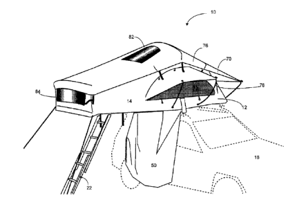
[0026] As shown in Figures 1, 2 and 3, the preferred tent 10 is not
symmetrical when viewed
from the exterior, consisting of a main portion 12 and an extended canopy
portion 14. The
main portion 12 of the tent 10 has a base 16 which rests on and is clamped to
a conventional
rack 46 on the roof-top of a vehicle 18, but also cantilevers out from the
vehicle 18 somewhat,
as shown in Figure 3. The extended canopy portion 14 provides additional
shelter outside the
vehicle 18, as well as providing some protection for the accessory/shoe bags
20 and access
ladder 22 from the elements.
[0027] As shown in Figure 4, the main portion 12 of the tent 10 is supported
by a system of
three frame poles 24 which are pivotally connected to the base 16. The base 16
consists of
two portions, which are hinged together with a pair of brackets 30. One
portion of the base 16
is fixed to the vehicle while in use (i.e. 'the fixed portion of the base
26'), while the other
portion of the base 16 (i.e. 'the pivoting portion of the base 28') pivots
between a stowed
position in which it lies over the fixed portion of the base 26, and a
deployed position in
which it cantilevers out from the vehicle 18. The pair of brackets 30 have
flange-like
members which stand off from the surface of the fixed 26 and pivoting 28
portions of the base
16, provide a pivot point that is raised from the surface of the fixed 26 and
pivoting portions
28 of the base 16. In this way, the fixed 26 and pivoting 28 portions of the
base 16 are spaced
apart from one another in the stowed position, leaving room for the mattress
32 and the three
frame poles 24. In the preferred embodiment the fixed 26 and pivoting 28
portions of the
base 16 will be spaced apart by about 8 V2", although other dimensions could
also be used.
The three frame poles 24 are connected to the pair of brackets 30 on the base
16, so that they
pivot as the tent 10 is assembled or stowed. The pivot points for the three
frame poles 24 are
spaced apart on the brackets 30, so that they do not interfere with one
another.
[0028] A detail of one of the pair of brackets 30 is shown in Figure 5. As
shown, each of the
brackets 30 consists of two parts, each part having a foot 34 which is screwed
to the U-
CA 02886590 2015-03-31
channel of the base 16, and an upright portion 36 having two holes. Each of
the three frame
poles 24 terminates in a clevis or yoke 38 that is attached to the frame pole
24 with a screw.
The clevises or yokes 38 allow the three frame poles 24 to pivot with respect
to the upright
portions 36 of the brackets 30, being attached with a bolt and a nylon nut 40
or locknut
arrangement. Note that the middle bolt 42 passes through two upright portions
36 of the
bracket 30 as well as through the clevis or yoke 38 of the middle frame pole,
so that the two
parts of the bracket 30 can pivot with respect to one another.
[0029] The fixed 26 and pivoting 28 portions of the base 16 are preferably
fabricated from
23mm thick aluminum honeycomb, with a U-shaped channel 44 fixed about the
perimeter.
Other thicknesses of aluminum honeycomb could be used, or other materials
which have
sufficient strength to provide the desired cantilever distance. For example,
the base 16 could
be fabricated from an aluminum frame filled with polyurethane foam, covered on
both sides
with a 0.4mm aluminum sheet. The aluminum honeycomb base described herein has
dimensions of 310cm length x 143cm width. As a result, the preferred
embodiment of the
tent as described herein has the following dimensions:
= tent dimensions open: 310cm length x 143cm width x 126cm height (i.e.
this is the
sleeping are, not including the canopy);
= tent dimensions closed: 125cm length x 143cm width x 30cm height;
= mattress: 240cm length x 140cm width x 6cm height;
= total pack size: 150cm length x 125cm width x 30cm height; and
= weight: 971bs.
This arrangement fits on a vehicle with a roof rack 46 wider than 37 inches,
and can be
adjusted to fit roof racks 46 smaller than 37 inches with minor modifications.
6
CA 02886590 2015-03-31
[0030] The U-shaped channel 44 fixed about the perimeter of the base 16 has a
groove 48 on
the underside (see Figures 7 and 12A), which is used to hold the travel cover
50 and to hold
the tent fabric in the conventional manner. But as will be explained
hereinafter, this groove
48 is also used to support the removable shoe/utility bags 20.
[0031] The frame arrangement in the main portion 12 of the tent 10 is
generally symmetrical.
The three pivoting frame poles 24 may have slightly different sizes so that
they nest together,
or they may be the same size so that they lay on top of one another in the
stowed position.
The three pivoting frame poles 24 are preferably 3/4" diameter aluminum, which
is light and
sufficiently strong for this application. Steel poles would be less expensive,
but would be
heavier than aluminum. Smaller diameter or light gauge aluminum could be used,
but it
would be less durable. Fibreglass or other materials may also be used as known
to one skilled
in the art. Because the three pivoting frame poles 24 have a small outside
diameter, it is not
necessary for them to nest together in order to provide a low-profile in the
stowed position.
Thus, it is preferred that they all be the same size.
[0032] The system of three pivoting frame poles 24 are connected together by
fabric straps
52. At one end, the fabric straps 52 are attached to the outside edge 54 of
the fixed portion of
the base, while at the other end, they are connected to the outside edge 56 of
the pivoting
. portion of the base. The fabric straps 52 are also frictionally
engaged at specific positions on
the three pivoting frame poles 24 so that the tent 10 has the desired shape in
the assembled
state. Thus, when the two base portions 26, 28 are pivoted into the deployed
position, the
fabric straps 52 will draw the three pivoting frame poles 24 with them,
pivoting them into
evenly spaced arrangement about the pair of brackets 30 on the base 16.
Conversely, when
the two base portions 26, 28 are pivoted into the stowed position, the fabric
straps 52 will
relax and allow the three pivoting frame poles 24 to pivot back into the
stowed position. The
two fabric straps 52 shown in Figure 4 are simply sewn into a loop at each
point in which
they cross the three pivoting frame poles 24, so the fabric straps 52 are in
frictional
engagement with the three pivoting frame poles 24. The fabric straps 52 could
be fixed to the
7
CA 02886590 2015-03-31
three pivoting frame poles 24, for example, using a single screw through the
fabric straps 52,
but this is generally not necessary.
[0033] The extended canopy 14 has an additional frame member, the canopy pole
58, which
is connected to the pivoting portion of the base 28 by way of a pair of
sockets 60 which pivot
in yokes or clevises 62 (see Figures 6 and 7), fixed to the outside edge of
the pivoting portion
of the base 28 (see Figure 3). The canopy pole 58 is removed completely when
the tent 10 is
disassembled and can be stowed on the top of the base 16 as shown in Figure 8.
In the
preferred arrangement, the canopy pole 58 slides through the four loops 64 on
the sides of the
base 16, and is fixed in position with a single loop 66 of Velcro. When the
tent 10 is
assembled, the ends of the canopy pole 58 are fitted into the sockets 60, and
the canopy pole
58 is rotated into position, supporting the tent fabric over the extended
canopy 14. The
extended canopy 14 is also deployed by way of a pair of guy lines 68 which are
fixed to the
ground with conventional stakes or pegs per Figures 2 and 3. The canopy pole
58 is
preferably fabricated from 3/4" diameter aluminum, like the three pivoting
frame poles 24.
[0034] All of the three pivoting frame poles 24 and the canopy pole 58 have
curved profiles.
Combining these curved profiles with the profile along the perpendicular axis
of the tent 10
(i.e. the long axis of the tent), provides a curved aerodynamic design in all
dimensions. This
results in less noise inside the tent 10 on a windy day, along with less
likelihood of damage.
As well, it allows rain and other precipitation to roll off of the tent 10
more easily than in
designs with flatter, horizontal surfaces. Preferably, the tent 10 should have
the curvature as
shown in the drawings, but the precise curvature is a trade-off between the
amount of space
inside the tent 10, and the degree of aerodynamics and precipitation runoff
that would be
provided. In other words, having less curvature (i.e. a larger curvature
radius) would provide
more room inside the tent 10, but poorer aerodynamics and reduced ability to
shed
precipitation.
[0035] The tent 10 itself is fabricated from water resistant 280g Poly Cotton
with flame
retardant, PU (polyurethane water-proofing) and mold/mildew resistant coating.
The rain fly
8
CA 02886590 2015-03-31
70 is fabricated from 420 denier waterproof Diamond Ripstop Polyester with
flame retardant,
PU and mold/mildew resistant coating. The travel cover 50 is fabricated from
2000 denier
PVC coated durable polyester. The precise dimensions of the tent 10, rain fly
70 and travel
cover 50 follow directly from the dimensions of the base 16 and frame.
[0036] As shown in Figures 9 and 10 the tent 10 preferable has large windows
72 on both
sides, and on the end of the tent 74 over of the fixed portion of the base.
The windows 72, 74
themselves are fabricated from "no-see-urn mesh", that is, extra-fine gauge
netting which
keeps out even very small bugs. Such netting is available in very sheer form
which maintains
a high level of visibility. The windows 72, 74 are fully zippered in that the
mesh is held to the
tent fabric by zippers, as are the window covers. The windows 72, 74 are also
provided with
a cover of tent fabric which can be unzipped and secured above with a loop and
bone system.
[0037] The windows 72, 74 are larger than those typically used, both in terms
of height and
width. The larger size provides for more light inside the tent 10, better
ventilation and better
viewing for campers. The larger window size for the side windows 72 is
facilitated in part by
the use of the generally semi-circular shape; typical windows in the prior art
are quite square
or rectangular. The windows 72, 74 are also equipped with awnings, which
consist of sheets
of fabric double-sewed to the tent above each window72, 74. While awnings are
available on
prior art tents, it was found that the existing awnings were not effective
with the larger semi-
circular side windows 72 of the invention. The existing awnings were not
shaped properly to
be fitted across the entirety of the arcuate upper profile of the windows,
resulting in a
bunching of loose material when they were deployed. In order to obtain awnings
76 that
properly fit the arcuate upper profile of the side windows 72, so they could
be connected all
the way to the horizontal edge of the side windows 72, awnings were roughly
installed and
then the superfluous material was removed. These new rounded awnings 76 are
double-sewn
to the tent fabric, and are extend out from the tent 10 using conventional
curved steel rods 78
as shown in Figures 1 and 3. The awnings 76 can be rolled-up or furled, being
held with a
typical loop and bone system.
9
CA 02886590 2015-03-31
[0038] As shown in Figures 1 and 10 the tent 10 preferably has dual skylights
80 on the
'roof' of the tent 10, with PVC windows 82 in corresponding locations on the
rain fly 70.
This provides additional light into the tent 10 during the day, as well as a
view of the sky at
night. The PVC windows 82 are sheets of frost-proof PVC, which has been double-
sewn into
the fabric of the rain fly 70. The skylights 80 in the tent 10 itself may
either be a similar
arrangement (i.e. PVC windows that have been double-sewn into the tent fabric)
or may be
the same arrangement as the side and end windows 72, 74 (i.e. a window of "no-
see-urn"
mesh with a flap of tent fabric, both of which are zippered onto the tent
fabric). Other than
the skylights and the curvature/dimensions of the rain fly 70, the rain fly 70
is of generally
conventional design being extended from the tent 10 with steel fly poles
and/or guy lines.
Note that the extended canopy 14 also has a PVC window 84 fabricated in the
same way as
the rain fly skylights 82, using PVC which has been double-sewn into the
fabric of the tent 10
(see Figure 3).
[0039] Quick release hand screws 86 as shown in Figures 11a, lib and lle are
provided to
facilitate easy installation and removal of the tent 10 from the roof rack 46
of a vehicle 18.
Two U-shaped aluminum slide channels 88 are provided across the bottom of the
fixed
portion 26 of the base 16. These U-shaped slide channels 88 are configured
with the open
side down, allowing slide plates 90 to slide back and forth so their positions
can be adjusted to
accommodate the particular roof rack 46 on the vehicle 18. Each slide plate 90
has a threaded
rod 92 extending from it, the threaded rod 92 comprising a carriage bolt or
being tack-welded
to the slide plate 90 (for example). Each hand screw 86 is of a knurled
polymer construction
and has an imbedded nut 94 which mates with the threaded rod 92. As shown in
Figure 11a,
the hand screws 86 are used to sandwich an arm of the vehicle roof rack 46
between a plate 96
and the U-shaped slide channels 88. Four of such mounting arrangements would
be used with
the typical tent 10, although a different number of such assemblies could also
be used, such as
six. Other variations on this design could also be used such as adding
locknuts or
lockwashers, using steel materials instead of aluminum, and adding neoprene or
rubber pads
to reduce scratching or damage to components.
CA 02886590 2015-03-31
[0040] Removable shoe/utility storage bags 20 are provided as shown in Figures
12a and
12b. The removable shoe/utility storage bags 20 are suspended from the
pivoting portion of
the base 28 as shown in Figure 3, so the user can store his/her shoes before
entering the tent
10. The removable shoe/utility storage bags 20 have two pockets: a large
primary pocket 100
which is fabricated from rain fly fabric, and a smaller pocket 102 on the
lower portion of the
front which is formed from "no-see-um" material. The large primary pocket 100
can be
closed with a Velcro strap 104 sewn into two portions of the removable
shoe/utility storage
bags 20. A piece of Velcro is also secured to the base 16 (not shown) so that
the removable
shoe/utility storage bags 20 can be secured during disassembly, or can be
positioned out of the
way during use. The removable shoe/utility storage bags 20 include a rubber
rod 106 which is
sewn into the top edge (see Figures 6 and 7). This rubber rod 106 is sized to
mate with the
groove 48 in the bottom edge of the U-channel 44. With this arrangement the
user can slide
the removable shoe/utility storage bags 20 sideways out of the groove 48 so
that they can be
removed completely.
[0041] The access ladder 22 preferably hinges to the underside of the pivoting
portion of the
base 28 using a pair of brackets 108, as shown in Figures 3 and 14. Thus, in
the stowed
position, the access ladder 22 rests on top of the pivoting portion of the
base 28 as shown in
Figure 8. The access ladder 22 is of aluminum construction and is extendible.
When the user
wishes to unfold the tent 10 from the stowed position, he/she simply pulls on
the bottom rung
of the access ladder 22, and the access ladder 22 and pivoting portion of the
base 28 will
unfold to the deployed position. The access ladder 22 also has two adjustable
pins 110, one
on each rail (see Figure 14). When the access ladder 22 is pulled out to the
deployed
position, these pins 110 may be set so that the access ladder 22 has the
proper angle for
access, and so that it bears part of the weight of the cantilevered pivoting
portion of the base
28.
[0042] The access ladder 22 is also hinged to the underside of the pivoting
portion of the base
28 so that it will not interfere with the door of the tent 10 (not shown). The
door is fabricated
with "no see urn" mesh and tent fabric, both of which are zippered to the tent
fabric. The door
11
CA 02886590 2015-03-31
is positioned between the main portion of the tent 12 and the outside edge 56
of the pivoting
portion of the base 28. The door material may be rolled up and held to the
roof of the tent 10
using a loop and bone system.
[0043] The tent 10 is also provided with a large rectangular utility pocket
112 as shown in
Figures 13a and 13b. This utility pocket 112 is fabricated from two layers of
"no-see-urn"
fabric, and is held in position with four bungee cords 114 or other elastic
means, and some
manner of removable connectors or carabiners, preferably plastic hooks with
fabric loops
secured to the U-channel of the base 16. The utility pocket 112 is used to
secure additional
parts, accessories or other camping gear in a secure position during travel.
[0044] Finally, the tent 10 is also preferably provided with the following
accessories:
= 2 inch thick, high density foam mattress;
= removable cotton mattress cover;
= Unisex emergency urinal; and
= D-ring 116 for hanging lighting (see Figure 4).
[0045] While particular embodiments of the present invention have been shown
and
described, it is clear that changes and modifications may be made to such
embodiments
without departing from the true scope and spirit of the invention.
[0046] All citations are hereby incorporated by reference.
12