Note: Descriptions are shown in the official language in which they were submitted.
CA 02886640 2015-03-27
WO 2014/071107
PCT/US2013/067927
GRINDER PUMP WITH REGENERATIVE IMPELLER
Technical Field
[0001] The disclosed embodiments of the present invention relate to
improvements in
a grinder pump, particularly a pump intended for use in a pressurized sewage
application. One difference from the known grinder pumps is the use of a
regenerative
turbine hydraulic instead of a centrifugal or progressing cavity hydraulic.
Background
[0002] A patent owned by the applicant, US 7,357,341, describes the
application of
grinder pumps in pressurized wastewater applications. In that patent, a two-
stage
vortex centrifugal pump is used to increase the output head achieved, compared
to a
single-stage centrifugal. Progressing cavity pumps have poor reliability in
abrasive
waste water application. Due to the unpleasant nature of maintaining a
submersible
pump in a sewage basin setting, this poor reliability makes progressing cavity
pumps
undesirable, even with their ability to provide relatively high head at low
flow rates.
[0003] Another patent owned by the applicant, US 8,128,360, describes a vortex
pump impeller that provides improved head by the incorporation of splitter
blades onto
the impeller face. From that patent, and other patents cited in its
prosecution, it is
known to use vortex pumps for liquids that contain a substantial amount of
foreign
matter such as solids and/or fibriform matter. The vortex chamber allows
foreign matter
to pass without clogging the impeller, which is rotationally mounted in an
adjoining
recessed chamber. A known trade-off from avoiding contact of foreign matter
with the
impeller is a loss of efficiency and head when compared to a more conventional
centrifugal pump.
[0004] A regenerative pump generally differs from a centrifugal pump in the
flow of the
fluid on the impeller. When a fluid encounters an impeller of a centrifugal
pump, the
fluid predominantly passes through the impeller only once, the encounter
resulting in the
fluid being centrifugally propelled into a volute that is radially beyond the
impeller. The
regenerative nature of the regenerative turbine lies in the many encounters
with the
impeller made by the fluid. Vanes of the regenerative turbine interact with
very tight
internal clearances to impose a circulatory pattern onto the fluid, so the
fluid enters and
1
CA 02886640 2015-03-27
WO 2014/071107
PCT/US2013/067927
exits the impeller vane multiple times before exiting the pump, with each
encounter
building up the pressure, so long as the clearances are tight enough to
prevent pressure
loss.
[0005] The need for these tight internal clearances has heretofore limited the
use of
regenerative turbines to so-called "clean liquids." The Hydraulic Institute
Standard 1.3
concerning regenerative turbine pumps says: "Due to the close clearances of
the dam
and side walls, it is necessary to have clean liquid. The particle size should
be no
greater than 0.025 mm (0.001 inches). Particles exceeding this parameter will
result in
reduced performance and the subsequent need to replace the close-fitting
casing and
impeller" (Section B1.3.1.5.1 "Clean Liquids).
[0006] This need for clean fluids leads some manufacturers of regenerative
turbine
pumps to use a strainer at the suction of the pump, to prevent solids from
entering the
turbine.
[0007] With this in mind, it is not surprising that US Patent 5,507,617
teaches
regenerative turbine pumps as being appropriately used in boiler feed water
systems,
rocket booster systems, car wash applications, chemical feed systems, chlorine
injection systems, condensate return systems, dry cleaning systems, electronic
cooling
systems, high pressure sprays, petroleum refining processes, air conditioning,
refrigeration and heating applications.
[0008] Another known application of regenerative turbine pumps is in
automobiles,
where the combination of high head at low flow and low power consumption make
them
ideal as fuel pumps.
[0009] It is therefore an unmet advantage of the prior art to provide
unexpectedly
improved efficiency, high head, and abrasion resistance from that of a vortex
pump
impeller and regenerative pumps as previously known.
Summary
[0010] This and other unmet advantages are provided by a pump for conveying
solids-
containing wastewater from a basin. Such a pump has a pump housing that is
adapted
to be arranged in the basin, so that an inlet thereof is positioned to receive
the solids-
containing wastewater. The pump housing has an outlet to eject wastewater
containing
2
CA 02886640 2015-03-27
WO 2014/071107
PCT/US2013/067927
comminuted solids that has been pressurized through an outlet of the basin. A
pump
chamber is a part of a flow conduit that is positioned in the pump housing
between the
inlet and the outlet.
[0011] A regenerative turbine impeller is arranged for rotation in the pump
chamber,
and a grinder is arranged for rotation in the pump housing between the inlet
and the
outlet.
[0012] In many of the embodiments, the grinder is arranged in the pump housing
between the inlet and the pump chamber.
[0013] In the preferred embodiments, the pump further comprises a drive shaft
with
both the regenerative turbine impeller and a cutter of the grinder mounted
thereupon.
Brief Description of the Drawings
[0014] A better understanding of the disclosed embodiments will be obtained
from a
reading of the following detailed description and the accompanying drawings
wherein
identical reference characters refer to identical parts and in which:
FIGURE 1 is a pressure (and efficiency) versus capacity chart for various
types
of pumps; and
FIGURE 2 is a side section elevation view of an embodiment of grinder pump
having a regenerative turbine hydraulic.
Detailed Description
[0015] The ongoing desire for energy efficiency in residential sewage pump
applications presents a need to replace centrifugal pump technology with a
more
effective technology. As will be shown, centrifugal pumps can provide a flow
rate that
easily meets or exceeds the requirements for residential sewage applications.
This is
particularly the case when a centrifugal pump is operated at a high pressure
head, as
the pump is likely operating at a flow rate well below the best efficiency
point (BEP) of
the pump. This results in higher power draw and motor amperage.
[0016] As a category, regenerative turbines can meet the flow rate needed at
an
equivalent or better pressure head and a lower power draw. Of these variables,
pressure head is the most important and a pressure of 200 ft Total Dynamic
Head
3
CA 02886640 2015-03-27
WO 2014/071107
PCT/US2013/067927
("TDH") is highly desirable. FIGURE 1 shows performance data for several
different
types of pumps, including some efficiency data. In this chart, the pressure
head
developed by a pump is read on the left side of the chart. For the efficiency
curves,
which are shown in dashed lines, the efficiencies are read on the right side
of the chart.
The maximum of the efficiency curve represents the BEP for the configuration.
Of
particular interest are the head and efficiency curves 2, 4 for a typical
single stage
centrifugal grinder pump (without the cutter feature) that is available from
Crane Pumps
and Systems and the head and efficiency curves 6, 8 for regenerative turbine
pump as
described herein.
[0017] Using known methods for sizing a centrifugal pump to have a BEP at 15
gpm, it
can be determined that the ideal minimum size of the internal passageway (the
"cutwater") is slightly less than 0.375 inch diameter. Experimental testing by
the
applicants shows that a cutwater of less than about .625 inches will tend to
clog with
solids. Using this larger cutwater to design the pump will increase the BEP to
approximately 45 gpm. Since the BEP flow rate is never met, a pump that runs
out to
30 gpm will be operating at a lower efficiency and require more horsepower,
or,
expressed in another manner, more amperage.
[0018] In testing conducted to date, using sand and pre-ground media as the
solids, a
regenerative turbine impeller has operated in a pump as described below
without
clogging, using a .625 inch passageway. It appears that the solids are stirred
by the
swirling induced by the impeller. It also appears to be possible that the
turbine blades
result in additional cutting, which may be even more accentuated when the
solids are of
a more fibrinoid nature. In the testing to date, the hydraulic end is capable
of discharge
pressures as high as 350 ft TDH, but is being operated at only about 200 ft
TDH.
[0019] These test results are very unexpected when the normal standards for
tolerating solids in a regenerative turbine are considered.
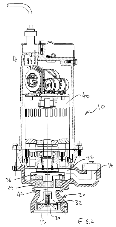
[0020] FIGURE 2 shows an embodiment of a single stage grinder pump 10
containing
a pump housing 20 with a pump chamber 22 and a grinder 30. Liquid, typically
containing foreign matter, enters the pump 10 through inlet 12, depicted in
this
embodiment as being on a lower surface of the pump. Since the pump 10 will
typically
be installed in a sump basin (not shown) that receives the liquid, the lower
surface
4
CA 02886640 2015-03-27
WO 2014/071107
PCT/US2013/067927
opening 12 is particularly useful for drawing down the level in the basin. The
motor 40
that provides rotational torque to the impellers in the pump 10 is actuated by
a level
sensing device (not shown) positioned in the basin, once a threshold level of
liquid has
accumulated. As the liquid and any entrained solids enter the inlet 12, the
solids are
comminuted in the grinder 30, where a rotating cutter 32 is mounted near or at
the end
of a drive shaft 42 driven by the motor 40. Since the structures of the
grinder 30 will
tend to throttle the flow rate to the pump chamber 22, it may be necessary in
some
situations to adjust the spacing of cutting elements (not shown) to optimize
flow.
Overall, the operation of a grinder 30 such as this is well-known in the art
and the
adjustments are within the capabilities of one of skill in this art.
[0021] In the depicted embodiment, the material, both liquid and entrained
solids, that
passes through the grinder 30 flows axially upward into the pump chamber 22.
At that
point the material flow past a raceway 24 and the liquid and entrained
materials are
subjected to the interaction of the rotationally stationary raceway and the
regenerative
turbine impeller 26, which is provided with vanes (not shown in Fig 2) and
driven by the
same drive shaft 42 that drives the cutter 32. The regenerative turbine
impeller 26
operates according to known principles and the liquid and entrained materials
end up,
after passing through the impeller vanes several times, in the outlet 14, from
which it is
piped to an elevated discharge point in the sewage basin. At this point, the
liquid has
been pressurized to the range of about 200 ft TDH and some significant
comminution
has occurred, so that it flows freely.
[0022] Having shown and described a preferred embodiment of the invention,
those
skilled in the art will realize that many variations and modifications may be
made to
affect the described invention and still be within the scope of the claimed
invention.
Thus, many of the elements indicated above may be altered or replaced by
different
elements which will provide the same result and fall within the spirit of the
claimed
invention. It is the intention, therefore, to limit the invention only as
indicated by the
scope of the claims.
5