Note: Descriptions are shown in the official language in which they were submitted.
CA 02886754 2015-03-30
- 1
Safety equipment of a lift installation
Description
The invention relates to a method of monitoring the movement of a lift cage
and to safety
equipment for carrying out the method.
A lift installation is installed in a building or attached thereto. It
essentially consists of a
cage which is connected by way of support means with a counterweight or with a
second
cage. The cage is moved along substantially vertical guide rails by means of a
drive which
acts selectably on the support means or directly on the cage or counterweight.
The lift
installation is used for transporting persons and goods within the building
over single or
several storeys.
The lift installation comprises devices for safeguarding the lift cage in the
case of failure of
the drive, support means or other lift components. These safeguards usually
include a
number of safety measures. A first safety measure is, for example, switching-
off of the lift
drive and actuation of drive brakes in order to stop the lift cage. This is
usually carried out
by interruption of a lift safety circuit. A further safety measure comprises
activation of
safety-brake devices or corresponding safety brakes. These can, when required,
brake
the lift cage on the guide rails or at brake rails. The safety measures are
these days
increasingly controlled by so-called electronic limiters which monitor
movements of the lift
cage.
A method for secure detection of movement states of a lift installation is
known from EP
1602610. In that case, several movement variables are detected at different
locations and
compared with one another and multi-stage braking measures are initiated if
impermissible
deviations are ascertained.
Monitoring equipment is known from a further publication W02010/107409,
wherein a
cleaned or filtered speed signal is calculated from a combination of speed
measurement
and acceleration measurement.
Similar monitoring equipment is known from JP2009/023823, wherein a cleaned
speed
signal is calculated from a combination of travel distance measurement and
acceleration
CA 02886754 2015-03-30
2
measurement. In that case, an integrator calculates speed changes between
measuring
points of the travel distance meter. The speeds determined from the data of
the travel
distance meter and speed change calculated by the integrator are added and a
reset logic
sets the integrator to zero on each occasion when, for example, the travel
distance meter
registers a measuring point.
The invention has the object of providing an alternative method and
corresponding safety
equipment for monitoring the movement of a lift cage, wherein a high level of
reliability and
security of the generated signal are to be achieved.
The solutions described in the following enable secure, rapid-reaction and
reliable
monitoring of the movement of a lift cage. Safety measures can be carried out
rapidly in
the case of an emergency.
According to one aspect of the invention the safety equipment for monitoring
the
movement of a lift cage detects, preferably by means of a first movement
sensor, an
acceleration of the lift cage and, preferably by means of a second movement
sensor, a
travel speed or travel distance of the lift cage. The user has various
possibilities for
detection of the second movement variable. In the case of use of a first
movement sensor
in the form of a tachometer use is usually made of a generator which, for
example, is
driven by a friction wheel moved along the guide rails together with the lift
cage. A
tachometer of that kind generates an electrical signal which is proportional
to the rotational
speed and thus to the travel speed and which can be converted by a converter
into,
preferably, a digital signal of the travel speed of the lift cage. In the case
of use of a first
movement sensor in the form of an incremental transmitter or other travel-
based sensor
system a corresponding signal of the travel speed of the lift cage is derived
from the
detected travel increments.
Moreover, the safety equipment determines, preferably in an integration
routine, an
integrated travel speed from the acceleration, which is detected by the first
movement
sensor, of the lift cage, wherein the travel speed detected or derived by the
second
movement sensor is used as a start variable of an integration cycle of the
integration
routine. Thus, on the one hand use is made of two different kinds of sensors
for detecting
the travel speed, which enables good mutual verification of the result, and on
the other
hand compensation is provided for, for example, a possible drift of the first
movement
CA 02886754 2015-03-30
3
sensor which detects the acceleration.
In addition, the integrated travel speed is now compared, preferably in a
first monitoring
module, with at least one predetermined limit speed and if the predetermined
limit speed is
exceeded one or more downstream safety measures are triggered.
Thus, a rapid and reliable method and system for monitoring the movement of
the lift cage
are provided. Reliable because the movement variables can be detected
redundantly by
different detection methods and rapid because by means of the detected
acceleration a
system, which is independent of slip and travel increment, for providing an
integrated
travel speed is present. Slip and travel increments lead, particularly in the
case of rapid
changes in movement, to values which are inaccurate and delayed in time.
In a preferred solution variant the integrated travel speed is compared,
preferably in a first
comparison routine, with the detected or derived travel speed and a new
integration cycle
is started, with use of the detected or derived travel speed, if a difference
between the two
travel speeds exceeds a first difference limit value or if a duration of the
current integration
cycle exceeds a predetermined time period. This comparison is carried out
sporadically at
relatively large intervals in time of, for example, up to one second and the
first difference
limit value is set to be generous.
For preference, a warning measure or safety measure is triggered if a
difference between
the two travel speeds exceeds a warning limit value or if a time plot of the
difference
between the two travel speeds exceeds an alarm value.
Small deviations between two different forms of detection are normal. Thus,
considered
over a longer time or a longer travel distance the detection result of a
tachometer or an
incremental transmitter is reliable, whilst rapid changes by detection of an
acceleration can
be recognised reliably. Thus, by the present solution it is possible to
reliably provide
compensation for, for example, drift of an acceleration sensor and at the same
time rapid
changes can also be reliably recognised.
In a preferred variant of solution, in addition a second acceleration of the
lift cage is
derived from the detected or derived travel speed of the lift cage and this
second
acceleration is compared, preferably in a second comparison routine, with the
detected
CA 02886754 2015-03-30
4
acceleration. In the case of agreement of the two accelerations an OK signal
is generated
and the OK signal is used for releasing the further integration of the
integration routine.
On the other hand, the safety measure is triggered if a difference between
these two
accelerations exceeds a defined acceleration difference limit value or if the
OK signal is
not issued. This comparison is preferably carried out frequently, for example
at an interval
of approximately 10 milliseconds, and the acceleration difference value for
comparison of
the two accelerations is calculated to be narrow. Obviously, the difference
limit values and
also the other limit values are fixed with consideration of the
characteristics and measuring
accuracies of the sensors present as well as of the lift installation itself.
Overall, with this construction the quality and correctness of the signals and
of the
derivation routines are verified and thus the reliability and security of the
monitoring
system improved.
In a preferred variant of solution the acceleration detected by the first
movement sensor is
compared, preferably in a further, third comparison routine, with the second
acceleration,
which is derived from the detected or derived travel speed of the lift cage,
of the lift cage in
mirror image to the second comparison routine. In this case as well the safety
measure is
triggered if the difference between these two accelerations exceeds the
defined
acceleration difference limit value. This comparison is also frequently
carried out in
parallel with the second comparison routine and the acceleration difference
limit value to
the comparison of the two accelerations is similarly calculated to be narrow.
These limit
values are also fixed with consideration of the characteristics and measuring
accuracy of
the sensors present and the lift installation itself, wherein for preference
use is made of the
same limit values as used in the second comparison routine.
The two routines, Le. the second and the third comparison routines, preferably
take place
in synchronism. Consequently, in the case of correct functioning of the
comparison
routines the result of the comparison should be substantially identical. These
comparison
values can thus be checked for equality in a supplementary assessment, wherein
obviously if equality is absent appropriate safety measures or servicing
requirements can
be undertaken.
The safety equipment for monitoring the movement of the lift cage preferably
comprises at
least one first processor unit and second processor unit and the sensors,
comparison
CA 02886754 2015-03-30
routines, monitoring modules and computing routines are apportioned to the two
processor
units. Thus, for example, the first movement sensor for detection of the
acceleration, the
integration routine, the first monitoring module and if need be the first and
second
comparison routines are executed as a component of the first processor unit or
as
functional groups with respect to the first processor unit. The second
movement sensor
for detecting the travel speed or the travel distance of the lift cage,
possible computing
routines and differentiators as well as, if need be, the third comparison
routine are
executed as a component of the second processor unit or as functional groups
with
respect to the second processor unit. A high level of reliability of the
safety equipment is
achievable with an architecture of separate processor units for processing and
independent parallel evaluation of the detected signals of the at least two
movement
sensor, since the processor units can initiate possible safety measures
independently of
one another.
The safety equipment preferably comprises a second monitoring module, which
compares
the travel speed, which is detected or derived by the second movement sensor,
with at
least one predetermined limit speed and which triggers the safety measure if
the
predetermined limit speed is exceeded. This second monitoring module is
preferably
associated with the second processor unit. The travel speed of the lift cage
is thus
separately monitored twice, whereby overall safety is increased.
The safety equipment preferably comprises a fourth comparison routine, which
compares
the travel speed, which is detected or derived by the second movement sensor,
with the
travel speed integrated by the integration routine and which triggers a
warning measure or
safety measure if the difference between the two travel speeds exceeds the
warning limit
value or if a time plot of the difference between the two travel speeds
exceeds an alarm
value. This fourth comparison routine is preferably associated with the second
processor
unit. Thus, the quality of the safety equipment is in addition redundantly
monitored in the
two processor units and overall safety is correspondingly improved.
Analogously to the
first comparison routine, the comparison of the fourth comparison routine is
also carried
out sporadically at relatively large intervals in time and the associated
first difference limit
value is set to be generous. The fourth comparison routine is thus the
comparison
element redundant with respect to the first comparison routine.
The safety equipment preferably comprises a third monitoring module, which
compares
CA 02886754 2015-03-30
= 6
the acceleration, which is detected by the first movement sensor, of the lift
cage with at
least one predetermined limit acceleration and which triggers a safety measure
if a
predetermined limit acceleration is exceeded. This third monitoring module is
preferably
associated with the first processor unit. A serious fault in the lift is
directly and rapidly
recognised by this third monitoring module if, for example, a high
acceleration suddenly
arises in the case of failure of support means. A braking measure can thus
take place
rapidly in the event of a fault of that kind.
The safety equipment can preferably trigger at least two different safety
measures,
wherein a first safety measure causes interruption of a lift safety circuit
and a second
safety measure causes actuation of a safety-brake device of the lift cage. The
lift safety
circuit is a central functional chain, which has to be intact or closed for
movement of the lift
cage, in the lift installation. Thus, the lift safety circuit is, for example,
opened if a shaft
door is opened. Interruption in the lift safety circuit has the effect that a
drive of the lift
installation is stopped and appropriate drive brakes are brought into action.
Insofar as the
safety equipment now ascertains an unusual deviation in the course of movement
or a
function of the safety equipment is no longer guaranteed, in the usual case as
a first safety
measure this lift safety circuit is interrupted and thus the lift installation
stopped. If the
deviation in the course of movement further increases notwithstanding the
first safety
measure or the deviations are very large then as a rule - as a second safety
measure -
safety brakes are actuated which firmly clamp the lift cage directly to guide
rails and thus
securely brake and hold the lift cage. The safety brakes are usually
controlled by a brake
control. Actuation of the safety brakes in these cases takes place by way of
this brake
control.
The second movement sensor of the safety equipment is preferably arranged in
the region
of a lift cage roller, preferably in the region of a support means deflecting
roller arranged
on the cage, and is driven by this. The travel speed or the travel distance of
the lift cage
can thus be accurately detected from a rotational movement of the lift cage
roller or the
support means deflecting roller. Lift cage rollers or also support means
deflecting rollers
are incorporated in the support structure of the lift cage. In that case, the
load on the roller
is of such a magnitude that slip is reduced and at the same time a fault in
the support
structure also leads, with a high level of probability, to influencing of the
movement
variable detected by the second movement sensor. This is reliably recognised
by the
aforesaid comparison routine and requisite safety measures can thus be
initiated.
7
The safety equipment preferably comprises first safety equipment and second
safety
equipment, wherein the two items of safety equipment are constructed as
explained in
the foregoing embodiments. The first safety equipment is in that case
preferably
arranged in the region of a first support means deflecting roller of the lift
cage and the
second safety equipment is arranged in the region of a second support means
deflecting roller of the lift cage. Overall safety is thus substantially
increased, since,
in total, use is made of two movement sensors for detection of the
acceleration of the
lift cage and for detection of the travel speed or the travel distance and are
compared
with one another and evaluated.
Accordingly, in one aspect, the present invention provides a method of
monitoring the
movement of a lift cage, comprising the steps: - detecting an acceleration
(AS) of the
lift cage, - detecting a travel speed (VM) or a travel distance (SM) of the
lift cage,
wherein if required, when the travel distance (SM) of the lift cage is
detected, the
travel speed (VM) is derived from the detected travel distance (SM) of the
lift cage, -
determining an integrated travel speed (VS) by integration of the detected
acceleration
(AS) of the lift cage, wherein the detected or derived travel speed (VM) is
used as a
start variable of an integration cycle, wherein the integrated travel speed
(VS) is
compared with the detected or derived travel speed (VM) and a new integration
cycle
is started if the difference (dV) between the integrated travel speed (VS) and
the
detected or derived travel speed (VM) exceeds a first difference limit value
or if the
duration of the current integration cycle exceeds a predetermined time period,
and -
comparing the integrated travel speed (VS) with at least one predetermined
limit
speed (VG) and triggering a safety measure if exceeding of the predetermined
limit
speed (VG) is established.
BREIF DESCRIPTION OF THE DRAWINGS
Exemplifying embodiments are explained in the following by way of examples and
schematic constructions, wherein:
Fig. 1 shows a schematic view of a lift installation in side view,
Fig. 2 show a schematic view of the lift installation in cross-section,
Fig. 3 shows a first embodiment of safety equipment,
CA 2886754 2019-11-27
7a
Fig. 4 shows a second embodiment of enlarged safety equipment and
Fig. 5 shows a third embodiment of enlarged safety equipment.
DETAILED DESCRIPTION OF THE PREFERRED EMBODIMENTS
The same reference numerals are used in the figures for equivalent parts over
all
figures.
A lift installation 1 is, as apparent in Fig. 1, installed in or attached to a
building and
serves for the transport of persons or goods within the building. The lift
installation
comprises a life cage 2, which can move upwardly and downwardly along guide
rails
7. A drive 6 serves for driving and holding the life cage 2. The drive 6 is,
for
example, arranged in the upper region of the building and the cage 2 hangs by
support
means 4, for example support cables or support belts, at the drive 6 or at
drive pulleys
6.2 of the drive 6. The support means 4 are guided by way of the drive pulleys
6.2 to
a counterweight 3. A drive motor 6.1 of the drive 6 drives the drive pulleys
6.2 and
thereby the support means 4 and thus the lift cage 2 and the counterweight 3.
A drive
brake 6.3 brakes, when required, the drive pulleys 6.2 or holds them in a rest
position.
The drive 6 can obviously also be
CA 2886754 2019-11-27
CA 02886754 2015-03-30
8
arranged in a different location in the building or in the region of the cage
2 or the
counterweight 3.
In the present example the support means 4 are guided by way of support means
deflecting rollers 5 of the lift cage 2. The lift cage 2 and - obviously -
correspondingly also
the counterweight 3 are suspended and driven in 2:1 relationship. A movement
sensor 14
for detecting a travel speed or a travel distance of the lift cage is arranged
at or in at least
one of the support means deflecting rollers 5. The signals of the movement
sensor 14 are
passed on to safety equipment 12.
The lift installation 1 is controlled by a lift control 11. The lift control
11 receives user
requests, optimises the operating sequence of the lift installation and
controls, usually by
way of a drive control 10, the drive 6. The lift control 11 or the drive
control 10 additionally
monitors the safety state of the lift installation and interrupts travel
operation if an unsafe
operating state arises. This monitoring is usually carried out with use of a
lift safety circuit
28, in which all safety-relevant functions are incorporated. Also included in
the monitoring
of that kind or in this lift safety circuit are, for example, shaft door
contacts which monitor
correct closing of the shaft doors and there is also monitoring of, for
example, limit
positions of the travel body 2, 3 in the lift shaft. Interruption of the lift
safety circuit 28
causes switching-off of the drive motor 6.1 and actuation of the drive brake
6.3, whereby
the lift installation 1 is usually, i.e. in the case of correct functioning of
the supporting and
drive system, stopped.
The lift cage 2 and, if required, also the counterweight 3 are additionally
equipped with a
brake system, which is suitable for securing and/or retarding the lift cage 2
or the
counterweight 3, respectively, in the case of unexpected movement or excess
speed, even
in the case of failure of the supporting and drive system. The brake system
comprises, in
the example, two identical safety brakes or safety-brake devices 8 which are
attached to
the lift cage 2 or the counterweight 3 on both sides thereof. The safety-brake
devices 8
are, in the example, arranged underneath the lift cage 2 and are electrically
activated by
way of a brake control 9. This brake control 9 is connected with the safety
equipment 12
of the lift installation, which monitors the movement of the lift cage 2 or
the counterweight 3
and, if required, causes actuation of the safety-brake devices 8 or interrupts
the lift safety
circuit 28. The brake control 9 and the safety equipment 12 can be separate
components,
but they can obviously also be combined into a functional group or even
integrated into a
CA 02886754 2015-03-30
9
lift or drive control 11, 10. A mechanical speed limiter, as is usually
employed, can be
eliminated, since the safety equipment 12 takes over this task. In the case of
appropriate
design of the safety-brake device 8, for example by redundant brake circuits,
appropriate
control algorithms and reset functions the drive brake 6.3 can possibly be
eliminated and
the lift safety circuit 28 can directly act on the brake control 9.
Fig. 2 shows the lift installation of Fig. 1 in a schematic plan view. The
brake system
comprises the two safety-brake devices 8. The two safety-brake devices 8 are
electrically
or mechanically coupled so that the two safety-brake devices 8 are actuated
together.
Unintended braking or safety-braking on one side is thus avoided. The two
safety-brake
devices 8 are preferably of identical or mirror-symmetrical construction and
they act on the
guide rails 7 arranged on either side of the cage 2.
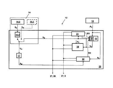
The safety equipment 12, which monitors the movement of the lift cage,
includes in a first
embodiment, as illustrated in Figure 3, a first movement sensor 13 for
detecting an
acceleration AS of the lift cage 2. This first movement sensor 13 is arranged
at the lift
cage 2 or fastened thereto so that it can detect at least the accelerations of
the lift cage in
vertical direction. An integration routine 15 calculates from this
acceleration an integrated
travel speed VS, wherein obviously the acceleration is corrected by the amount
of
gravitational acceleration.
In addition, the safety equipment 12 includes a second movement sensor 14,
which with
reference to Figure 1 is attached to one of the support means deflecting
rollers 5 and
which, in one embodiment, detects angular movements of the support means
deflecting
roller 5 by means of an incremental counter 14.2. With knowledge of the roll
diameter of ,
the support means deflecting roller 5 a travel distance SM is detected
therefrom and from
this travel distance SM a travel speed VM is derived by means of a distance
differential
computer 14.3. Alternatively, instead of the incremental counter 14.2 and the
distance
differential computer 14.3 use can be made of a tachometer 14.1 which directly
detects the
travel speed VM, as illustrated by dashed lines in Figure 3. In addition, a
differential
routine 17 calculates a derived acceleration AM from the travel speed VM
detected or
derived by the second movement sensor 14.
The signals of acceleration sensors, such as used for detecting accelerations
of the lift
cage 2, have small inaccuracies attributable to the system. This leads by way
of the
CA 02886754 2015-03-30
integration to summation of these inaccuracies, which over a longer period of
time leads to
falsification of the result. In order to compensate for these inaccuracies or
drift a new
integration cycle, with use of the travel speed VM detected by the second
movement
sensor as a start variable, is started at an interval in time if specific
travel events occur or if
a difference dV between the travel speed VM detected by the second movement
sensor
and the travel speed VS integrated by the first movement sensor exceeds a
defined
amount. For that purpose, a reset logic 16 is added to the integration routine
15. The
reset logic 16 controls the integration sequence of the integration routine 15
and supplies
the travel speed VM, which is detected by the second movement sensor 14, on
each
occasion as start variable of an integration cycle. In the embodiment of
Figure 3 for that
purpose a first comparison routine 21 compares the integrated travel speed VS
of the first
movement sensor 13 with the detected travel speed VM and generates a warning
signal
R1 at the reset logic 16 if a difference dV between the two travel speeds VS,
VM exceeds
a predetermined value of, for example, approximately 5% of a nominal speed. As
soon as
this warning level R1 is present at the reset logic 16 a new integration cycle
is started,
wherein then the travel speed VM detected by the second movement sensor is set
as start
variable of the new integration cycle. Continuous compensation is thus in
principle
provided for drift.
The comparison routine 21 in that case operates at long intervals in time of,
for example,
approximately 500 milliseconds. If the comparison routine 21 now establishes
that the
difference dV within this period of time is large, for example more than 10%
of the nominal
speed, a safety measure 27 is triggered. In a first step the lift safety
circuit 28 is thereby
interrupted and thus the lift installation stopped. If the difference dV
within this period of
time is even larger, for example more than 15% of the nominal speed, a brake
control 9 for
activation of the safety-brake devices is directly activated.
In addition to the first comparison routine 21 a second comparison routine 22
checks
correct functioning of the first and second movement sensors 13, 14 in that it
compares
the acceleration AM derived from the second movement sensor 14 with the
acceleration
AS detected by the first movement sensor 13 and obviously cleaned with respect
to
gravitational acceleration. This second comparison routine 22 operates, by
contrast to the
first comparison routine 21, at high cyclic frequencies. An operating time
interval of the
second comparison routine 22 is, for example, approximately 10 milliseconds.
As long as
the second comparison routine establishes approximate agreement of the two
CA 02886754 2015-03-30
11
accelerations AM, AS an OK signal R2 is issued at the reset logic 16. This has
the effect
that the integration routine 15 is continued. If the two accelerations AM, AS
significantly
differ from one another the OK signal is stopped, whereupon the reset logic 16
uses the
respective greater one of the two travel speeds VS, VM for a possible new
integration
cycle. At the same time the safety measure 27 is selectively initiated in that
depending on
the size of the difference between the two accelerations AM, AS merely the
lift safety
circuit 28 is interrupted or, possibly with a delay in time, the brake control
9 is activated.
The values indicated in the examples are merely by way of example. The time
values,
difference values and other values can be established in dependence on sensors
used,
travel speed, etc.
In addition, the safety equipment according to Figure 3 includes a first
monitoring module
18, which compares the integrated travel speed AS with a permissible limit
speed VG and
triggers the safety measure 27 if the permissible limit speed VG is exceeded.
Usually, as
a first safety measure 27 the lift safety circuit 28 is interrupted if the so-
called nominal
speed of the lift installation is exceeded by approximately 10% or the safety-
brake device 8
is actuated if the nominal speed is exceeded by more than 15%.
Thus, the functioning of the two movement sensors is checked and monitored by
means of
comparison of the accelerations AM, AS, compensation for drift of the
integrated travel
speed VS is provided by means of sporadic comparison of the travel speeds VM,
VS and
functioning of computation routines is checked. The travel speed of the lift
cage can thus
be reliably monitored.
In the example, the calculation routines 15, 17, 14.3, the comparison routines
21, 22 and
the monitoring module 18 are arranged on a circuitboard or on a processor unit
25. In
addition, the first movement sensor 13 can also be a component of this
processor unit 25
and the entire safety equipment 12 can be arranged in the region of support
means
deflecting rollers 5 (see Figures 1 and 2). The arrangements can obviously
also be
selected to be different. Thus, by way of example, the second movement sensor
14
together with the differential routine 17 can form a processor unit and the
remaining
components such as integration routine 15, the comparison routines 21, 22 and
the
monitoring module 18 can be combined in another processor unit.
CA 02886754 2015-03-30
12
In a further embodiment, as is illustrated in Figure 4, the safety equipment
12 comprises,
in addition to the safety equipment explained in the preceding, a second
monitoring
module 19 which compares the travel speed VM, which is detected or derived by
the
second movement sensor 14, with an allowable limit speed VG2 and, analogously
to the
first monitoring module 18, triggers the safety measure 27 if the allowable
limit speed is
exceeded. As a rule, the permissible limit speed VG2 is set to be identical
with the limit
speed VG. In addition, the safety equipment 12 includes a fourth comparison
routine 24,
which in partial analogy to the first comparison routine 21 compares the
travel speed VM
detected or derived by the second movement sensor 14 with the integrated
travel speed
VS of the first movement sensor 13. This fourth comparison routine 24
similarly triggers,
like the first comparison routine 21, a safety measure 27 if the difference
within a set time
interval is large.
In this embodiment the integration routine 15 with associated reset logic 16,
the first and
second comparison routines 21, 22 and the monitoring module 18 are arranged on
a first
processor unit 25. This first processor unit 25 is associated with the first
movement sensor
13 or the first movement sensor 13 is integrated in the first processor unit
25. The
remaining subassemblies such as the differential routine 17, the monitoring
module 19 and
the fourth comparison routine 24 are arranged on a second processor unit 26 in
connection with the distance sensor 14.2 and the distance differentiator 14.3
or the speed
tachometer 14.1. The security of this safety equipment with two processor
units 25, 26 is
particularly reliable, since important functions are processed in redundant
manner and the
two processor units 25, 26 can initiate safety measures 27 independently of
one another.
A further embodiment, as illustrated in Figure 5, further includes,
additionally by
comparison with the preceding embodiments, a third monitoring module 20, which
is
arranged at the first processor unit 25 and which compares the acceleration
AS, which is
detected by the first movement sensor 13, of the lift cage with at least one
predetermined
limit acceleration AG and triggers a safety measure 27 if the predetermined
limit
acceleration AG is exceeded. This third monitoring module 20 is provided
primarily for the
purpose of rapidly detecting a possible freefall or crashing down of a lift
cage.
Moreover, provided in this embodiment is a third comparison routine 23 which
is arranged
at the second processor unit 26 and which analogously to the second comparison
routine
22 checks correct functioning of the first and second movement sensors 13, 14
in that it
CA 02886754 2015-03-30
13
compares the acceleration AS, which is detected by the first movement sensor
13 and
obviously cleaned with respect to gravitational acceleration, with the
acceleration AM
derived from the second movement sensor 14 and triggers possible safety
measures if the
comparison reveals excessive deviations.
The illustrated embodiments can be varied by the expert. Depending on the
required
safety level, redundant comparison routines 23, 24 or the redundant monitoring
module 19
can be omitted. The entire safety equipment 12 can possibly be duplicated in
one of the
embodiments or a variation thereof so that one safety equipment is arranged at
a first
support means deflecting roller 5.1 and a second safety equipment is arranged
at a
second support means deflecting roller 5.2. Safety of the entire installation
is improved by
this redundant arrangement. In
addition, instead of the incremental sensors or
tachogenerators mentioned in the embodiments use can obviously also be made of
absolute position systems or other travel measuring systems. The method and
the safety
equipment are illustrated and explained in the embodiments in the application
with respect
to monitoring the movements of the lift cage. The method or equipment can
obviously also
be used in the same mode and manner at the counterweight.