Note: Descriptions are shown in the official language in which they were submitted.
CA 02886870 2015-04-01
BOTTLE WITH MULTIPLE COMPARTMENTS
The present application claims priority to United States Application Number
62/014,402 filed June 19,
2014, the contents of which are incorporated herein by reference.
FIELD OF THE INVENTION
[0001] This specification relates generally to containers for holding liquid,
and more particularly to a
bottle with multiple compartments for storing different constituent liquids
for mixed drinks that pours the
liquids at consistent ratios.
BACKGROUND
[0002] Mixed drinks such as juice mixtures and mixed alcoholic beverages are
commonly consumed in
modern society.
[0003] Mixed beverages are generally prepared using one of two methods. In a
first method, the
constituent liquids are mixed in a bottle at a bottling facility and are
provided in a pre-mixed state to a
retailer. An example of this method would be a blueberry iced tea drink. In
this example, blueberry juice
and iced tea are dispensed into the same bottle at the bottling facility so
that a consumer does not have to
mix the ingredients themselves. One deficiency of this method is that the
constituent ingredients will
generally have different densities, which leads to one of the liquids
remaining at the bottom of the bottle
and often forming a sediment layer. If a consumer pours the beverage without
mixing vigorously, it is
likely that the consumer will receive a significantly larger portion of one of
the constituent liquids than
was intended by the beverage provider given that the constituent liquids are
not mixed effectively.
Commonly artificial flavors and colors are added to these types of mixed
drinks so that the integrity of the
ingredients does not break down.
[0004] In a second method of preparing mixed beverages, a consumer must
purchase the constituent
ingredient liquids of the desired beverage, measure the constituent
ingredients, and pour accordingly.
This method can be cumbersome, especially when the consumer must buy many
different constituent
liquids that are required by the mixed drink recipe. Furthermore, the consumer
must measure each of the
ingredients precisely before pouring which is dependent on the size of the
glass being used to drink the
beverage. Many consumers do not know the proper drink recipes and therefore
have to conduct some
research first in order to obtain the desired mixing proportions.
Additionally, it can be dangerous if
alcohol is one of the ingredients in a drink recipe and the consumer includes
too high of a proportion of
alcohol in the mixed drink.
1
CA 02886870 2015-04-01
[0005] There is therefore a need for improved methods and products which
overcome or ameliorate one
or more of the defects of the prior art.
DESCRIPTION OF THE DRAWINGS
[0006] The invention will be better understood with reference to the drawings,
in which:
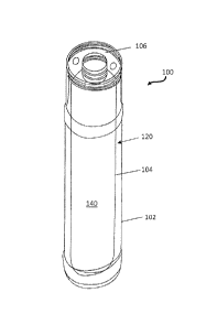
[0007] FIG. 1 is a front perspective view of a bottle having multiple
compartments, according to an
embodiment;
[0008] FIG. 2 is front view of the bottle of FIG. 1;
[0009] FIG. 3 is a top view of the bottle of FIG. I;
[00010]FIG. 4 is an exploded view of a bottle having multiple compartments and
including a cap,
according to an embodiment;
[00011]FIG. 5 shows a bottom view of a cap in accordance with an embodiment,
showing elements of the
cap that seal a multiple compartment bottle;
[00012]FIG. 6 shows a top-down cross-sectional view of a bottle having an
inner container positioned
within an outer container, according to an Linbodiment;
[00013]FIG. 7 shows a bottom perspective view of an embodiment of a collar;
[00014]FIG. 8 is a top perspective view of the collar of FIG. 7;
[00015]FIG 9 is a top view of a further embodiment of a collar;
[00016] FIG 10 is a bottom perspective view of the collar of FIG 9;
[00017]FIG 11 is a further top perspective view of the collar of FIG 9;
[00018]FIG. 12 is a front perspective view of a bottle having multiple
compartments according to a
further embodiment;
[00019]FIG. 13 is a top view of a collar for use with the embodiment of FIG.
12;
[00020]FIG. 14 is a side view of the collar of FIG. 13;
[00021]FIG. 15 is a bottom view of the bottle of FIG. 12;
2
CA 02886870 2015-04-01
[00022] FIG. 16 is an exploded view of the bottle of FIG. 12;
[00023] FIG. 17 is a bottom view of a cap in accordance with an embodiment of
the bottle of FIG. 12; and
[00024]FIG. 18 is a cross-sectional view of the bottle of FIG. 12.
[00025]For convenience, like reference numbers and designations in the various
drawings indicate like
elements and components.
DETAILED DESCRIPTION
[00026] A beverage bottle for efficiently mixing at least two liquids upon
pouring is provided. In an
embodiment, the bottle includes an outer container for holding a first liquid,
and at least one inner
container positioned within the outer container for holding a second liquid. A
collar is included for
securing the inner container within the outer container. The collar has an
outer surface for engaging with
the wall of the outer container, and an aperture for engaging with the spout
of the inner container. The
first and second liquids are kept separate until they are poured from the
bottle, at which time the liquids
are mixed at a predetermined ratio.
[00027] In another aspect, the collar is positioned at the top of the outer
container. The collar may include
a plurality of apertures positioned above the first liquid for pouring the
first liquid and for allowing
airflow into the outer container during toe pouring process. The ratio of the
larger collar aperture
(engaged with the inner container spout) and the smaller collar apertures
(positioned above the first
liquid) may be selected to pour the first and second liquids at a
predetermined ratio.
[00028] In an aspect, at least one of the inner and outer containers comprises
polyethylene terephthalate.
In another aspect, at least one of the inner and outer containers comprises
glass. In various aspects, the
inner and outer containers are transparent so that their respective liquids
may be viewed from the outside
of the bottle.
[00029]In yet another aspect, the largest distance between the walls of inner
container and the outer
container when the inner container is positioned within the outer container,
is at partly determined to
overcome any refraction of light through the inner container so that the first
and second liquids are
distinguishable from the outside of the bottle to a consumer.
[00030] In an embodiment, a beverage bottle for mixing at least two liquids
upon pouring is described.
The bottle includes an outer container for holding a first liquid. The outer
container includes a bottom, a
circumferential wall, and an open spout. The bottle includes at least one
inner container positioned within
3
CA 02886870 2015-04-01
the outer container for holding a second liquid. The inner container includes
a bottom, a circumferential
wall, and an open spout. The bottle further includes a collar engaging the
outer container and the inner
container and holding the inner container in a fixed position relative to the
outer container. The collar
defines a first aperture in fluid communication with the inner container and a
second aperture in fluid
communication with the outer container. A lateral distance 915 between a first
pouring edge 923 of the
first aperture 902 and a first pouring edge 921 of the second aperture 906 is
eight millimeters or less. The
first pouring edge 921 of the first aperture 902 is the edge of the aperture
902 that the liquid pours over
when and the first pouring edge 923 of the second aperture 906 is the edge of
the aperture 906 that the
liquid over. The pouring edges 921, 921 are generally the sides of the
aperture closest to the outside
perimeter of the collar 106.
[00031]Reference is first made to FIGS. 1 to 5 to describe a multiple
compartment bottle 100 according
to an example embodiment. FIG. 1 illustrates a perspective view of the bottle
100 and FIG. 2 illustrates a
front view of the bottle 100. FIG. 3 is a top view of the bottle 100 and FIG.
4 is an exploded view of the
bottle 100. In the embodiment of FIG. 4, the bottle 100 also includes a cap
108 which is not shown in
FIGs. 1 to 3.
[00032] The multiple compartment bottle 100 is adapted to hold, and keep
separate, at least two distinct
liquids to be mixed when a user pours the liquids with a cap 108 (not shown in
FIGs 1 and 2 but shown in
FIG. 5) removed from the bottle 100. In an embodiment, the multiple
compartment bottle 100 may store
and keep separate an alcoholic spirit (e.g. vodka) and juice (e.g. orange
juice) in separate compartments
(also referred to herein as containers) within the bottle 100. The multiple
compartment bottle 100 is
configured to mix the vodka and orange juice in another container such as a
glass as the vodka and orange
juice are poured out of their respective containers. The multiple compartment
bottle 100 is designed such
that a desired pour ratio is achieved when the liquids are poured, meaning
that the ratio between the
respective liquids is constant (within a predetermined range) when poured, no
matter how much of the
original volume of the liquids remains in the bottle.
[00033]In some embodiments, the multiple compartment bottle 100 has an outer
container 102 for
holding a first liquid 120 and at least one inner container 104 within the
outer container 102 for holding a
second liquid 140. The inner container 104 may also be referred to as an inner
bottle and the outer
container 102 may also be referred to as an outer bottle. The inner container
104 and the outer container
102 each include a bottom (which may also be referred to as a base), a
circumferential wall and an open
spout. More particularly, a base 116 (FIG. 2) of the outer container 102 and a
circumferential wall 107 of
the outer container 102 contain the first liquid 120 therebetween and an open
spout 112 is located at a top
4
CA 02886870 2015-04-01
end of the outer container 102. The open snout 112 is the open end of the
outer container 102.
[00034] Similarly, a base 118 (FIG. 2) of the inner container 104 and a
circumferential wall 109 of the
inner container 104 contain the second liquid 140 therebetween and an open
spout 114 is located at a top
end of the inner container 104. The open spout 114 is the open end of the
inner container 104.
[00035] As shown, the inner container 104 fits within the outer container 102,
meaning that the volume of
inner container 104 is less than the volume of outer container 102. However,
the volume of the liquid in
the inner container 104 could be more than the volume of the liquid in the
outer container 102 since the
outer container 102 is occupied, in part, by the inner container 104. As will
be described herein, the inner
container 104 may be secured within the outer container 102 using one or more
techniques. In various
embodiments, the rotational position of inner container 104 within the outer
container 102 may be
relevant, and various alignment mechanisms may be employed to ensure a desired
relative position of
inner container 104 with respect to outer container 102.
[00036]In various embodiments, a desired visual/aesthetic effect may be
achieved by selecting the
respective liquids 120,140 of various colors. For example, in some embodiments
the first liquid 120 is
colorless (e.g., vodka) and the second liquid 140 is colored (e.g., a juice
such as cranberry juice). In such
an arrangement, the inner container 104 may be visibly distinguishably from
the outer container 102 in an
aesthetically pleasing fashion. It will be appreciated that any combination of
colored and/or colorless
liquids may be selected depending on the effect and mixed drink combination
(after pouring) that is
desired.
[00037] In some embodiments, the distance between the wall of the outer
container 102 and the inner
container 104 is within a range of 0.1 to 2 inches (when the inner container
104 is positioned within the
outer container 102). Such a configuration may overcome the refraction effect
and allow the inner liquid
140 to be distinguishable from the outer liquid 120. Other ranges and
configurations may also provide
that the inner and outer liquids 140,120 are distinguishable.
[00038] Referring to FIGS. 1, 3 and 4, a collar 106 may be employed to secure
the inner container 104
within the outer container 102. The collar 106 may include a plurality of
apertures 302,304,306 (FIG. 3)
which are configured to achieve several purposes.
[00039] The collar engages the outer container 102 and the inner container 104
to hold the inner container
in a fixed position relative to the outer container. The collar is positioned
at a top end of the outer
container proximate the spout of the outer container.
CA 02886870 2015-04-01
[00040]The collar 106 may be threadably engaged with the outer container 102.
As shown, the perimeter
of collar 106 may have threads that can 1:),F engaged with corresponding
threads on an interior of a spout
114 (FIG. 5) of the outer container 102. Likewise, the aperture 306 of the
collar 106 may have an interior
wall that may be threadably engaged with a spout 112 (FIG. 5) of the inner
container 104. The collar 106
operates to secure the inner container 104 within the outer container 102. In
some embodiments, a thread
sealant such as an adhesive, thread tape, etc. may be used to further secure
the positioning of the collar
and inner container 104.
[00041] Other attachment techniques for attaching the collar 106 to the outer
container 102 and/or the
inner container 104 may also be used. For example, in some embodiments, the
collar 106 may friction fit
within the outer container 102. To facilitate such a fit, the interior of the
outer container 102 may include
one or more protrusions or other features at or near its spout 112 which may
exert a force on the collar
106 to hold it in place. Similarly, the collar may friction fit with the inner
container 104 at the spout 114
of the inner container 104. The collar 106 functions to secure the inner
container to the bottom of the
outer container by engaging with the collar.
[00042] In at least some embodiments, to provide additional rigidity to the
outer container and/or the inner
container, the inner or outer container may include one or more structural
and/or strengthening features.
For example, in an embodiment, the outer container may include one or more
ribs on or around the spout
112. The ribs or rings may provide additional rigidity to the bottle. In some
embodiments, the inner
container may include one or more vertical indentations along a side of the
inner container.
[00043]Furthermore, while the embodiment of FIGs. 1 to 5 illustrates a collar
106 which attaches to the
inner container 104 at an exterior perimeter surface of the inner container
104 (i.e. at the exterior side of
the spout 114), in other embodiments, the collar 106 may be inserted within
the spout 114 of the interior
and may be secured with threading or by a friction fit or another suitable
technique. Similarly, while the
embodiment of FIGs. 1 to 5 illustrates a collar 106 which attaches to the
outer container 102 at an interior
surface of the inner container 104 (i.e. at the interior side of the spout
112), in other embodiments, the
collar 106 may be attached to the exterior side of the spout 112.
[00044] The collar 106 may, in at least some embodiments, be referred to as a
ring. In some
embodiments, the collar 106 may be referred to as a first cap (as
distinguished from the cap 108, which
may be referred to as a second cap in such embodiments),In various
embodiments, the collar 106 may be
positioned near the top of the outer container 102 (as shown in the Figures),
at the bottom of outer
container 102, or anywhere along the length of outer container 102. In some
embodiments, more than one
collar 106 may be positioned within the outer container 102 to secure the
inner container in multiple
6
CA 02886870 2015-04-01
locations. As noted above, the collar 106 may be engaged within the outer
container using a threaded
connection as shown, using a friction fit, secured with an epoxy, or by any
suitable means. Likewise, the
inner container 104 may engage with the aperture 306 of the collar 106 using a
threaded connection as
shown, by way of a friction fit, or by any suitable means.
[00045] An aperture 306 (which may be referred to as a first aperture)
provided on the collar 106 is in
fluid communication with the spout 114 of the inner container. That is, the
first aperture 306 may form a
spout together with the spout 114 such that the fluid 140 within the inner
container 140 exits from the
aperture 306 and the spout 114 during pouring. As shown in FIG. 3, one or more
other apertures 302,304
are positioned on the collar 106 above the liquid 120 in the outer container
102. At least one of apertures
304, 302 is in fluid communication with the spout 112 of the outer container.
That is, at least one of these
other apertures allows for liquid 120 to exit the outer container 102. Another
one of the apertures 304,302
may allow airflow into the outer container 102 during pouring to increase the
effectiveness of the pouring
operation. This other aperture may act as and be refened to as a vent, in at
least some embodiments.
The vent is also in fluid communication with the spout to allow air to enter
the outer container 102.
[00046] In the example embodiment, the apertures 304, 302 that act as the vent
and the spout for the outer
container 102 are similar in configuration. More particularly, both of these
apertures are of the same size
and are of the same distance from the first aperture 306. Such a configuration
allows the apertures 304,
302 to be used interchangeably. However, in other embodiments (some examples
of which will be
discussed below), the apertures 304, 302 may be different from one another.
[00047]Referring to FIGS. 4 and 5, a cap 108 for sealing the multiple
compartment bottle 100 is shown.
In FIG. 4, the cap 108 is shown along with other components of the bottle 100.
In. FIG. 5, the cap 108 is
shown in isolation, and is illustrated from the bottom of the cap (i.e. the
side of the cap 108 that is
configured for attaching to the bottle 100 and sealing one or more of the
apertures 302, 304, 306.
[00048]In the example, the cap 108 includes an outwardly projecting
cylindrical wall 702 which is
configured to enter the first aperture 306 and seal the inner container spout
114. A further wall 704 is
configured to enclose and seal the spout 112 of the outer container 102 from
the outside. In this way, the
cap 108 is adapted to keep separated the first and second liquids and to
confine the liquids to their
respective containers while the cap is in place. The walls 702, 704 may engage
with their opposing
surfaces of inner container 104 and outer container 102 by way of friction,
threads, and the like. In some
embodiments, the cap 108 includes a locking mechanism for further securing the
cap 108 in place once it
is engaged tightly with inner and outer containers 104,102.
7
CA 02886870 2015-04-01
[00049] In one or more embodiments, the cap 108 can be used as a cup for
drinking. For example, the
configuration and size of the cap 108 can be such that, once removed, it
operates as a cup or container for
a drink. By way of further example, the cap can have a planar surface so that
it can rest on a table without
tipping over and the cap can have a depth substantial enough for holding a
suitable amount of beverage
for drinking.
[00050]Referring to FIG. 6, a top down cross sectional view of the multiple
compartment bottle 100 is
shown to illustrate shapes of the inner container and the outer container. In
the example, the outer
container 102 contains a transparent liquid 120 and the inner container 104
contains a colored liquid 140.
In some embodiments, the transparent liquid 120 is an alcoholic spirit (e.g.
vodka) and colored liquid 140
is a flavored beverage (e.g. juice). By placing a transparent liquid in the
outer container, the contents of
the inner container can be viewed. That is, the transparent liquid provided in
the outer container allows
for viewing of the non-transparent liquid contained in the inner container.
This can allow a user to easily
assess the amount of liquid in each container.
[00051] As illustrated, the outer container 102 cross sectional shape may be
substantially oval/elliptical
such that the circumference is not defined by a constant radius around the
center of the container. In the
embodiment illustrated, the inner container 104 cross sectional shape is
substantially circular such that the
circumference is defined by a substantially constant radius around the center
of the container. However,
in another embodiment, the inner container 104 cross sectional shape is
oval/elliptical such that the
circumference is not defined by a constant radius around the center of the
container
[00052] The distance between the outer container 102 and the inner container
140 may vary between a
distance L and a distance S. The two distances may be selected so that the
colored liquid 140 is clearly
distinguishable from the colorless liquid 120 when the bottle 100 is viewed
from the outside. Due to the
refraction of light passing through the bottle 100, a predetermined minimum
distance may enable a viewer
to distinguish between the outer and inner liquids 120,140. It should be
appreciated that with a suitable
geometry, the liquids 120,140 may be distinguishable as long as they are
different colors (or both are not
colorless). Also, the embodiments contemplated are not limited to the shapes
and configuration as shown
in the drawings, but rather, a multitude of shapes and configurations of
containers 102,104 are
contemplated.
[00053]In some embodiments, the ratio between the radii of the aperture 306
and the apertures 302,304
may be selected so that a desired ratio of liquids 120,140 is dispensed during
a pour, within an acceptable
margin of error. In some embodiments, the ratio between the larger aperture
306 and the smaller
apertures 302,304 is within a range of 2:1 to 5:1.. In some embodiments, the
ratio range may be
8
CA 02886870 2015-04-01
predetermined to correspond to a particular drink, such as a vodka and orange
juice drink with known
quantities of alcohol and juice. For example, a particular vodka and orange
juice drink (screwdriver) may
contain 2 oz. of vodka for every 5. oz. of orange juice. To achieve this
desired proportion, the ratio of the
larger aperture 306 to the smaller apertures 302, 304 is carefully selected so
that this constant ratio (2:5 of
vodka to orange juice) is poured from a multiple bottle 100, no matter how
much of the inner and outer
liquids 140,120 remain in the bottle 100.
[00054] In some embodiments, the bottle 100 includes an alignment mechanism
for ensuring that the
inner container and outer container are positioned in a desired position
relative to each other. The
alignment mechanism may include one or more protrusions on the bottom of (and
within) the outer
container 102, that are designed to fit into corresponding cavities
(indentations) on the outside of the base
118 of the inner container 104. In some embodiments the bases of the inner and
outer containers are
secured to each other such that the inner and outer containers cannot move
relative to each other. In other
embodiments, the alignment mechanism ensures that the inner container is
positioned relative to the outer
container in a general orientation, but the inner container is not secured to
the outer container via the base.
In various embodiments, the shapes of the outer container 102 and the inner
container 104 ensure that the
containers 102,104 are positioned relative to each other in a desired
configuration. For example, for an
embodiment in which both the outer container 102 and the inner container 104
have substantially
ellipsoid shapes, if the long axis of the inner container 104 is longer than
the short axis of the outer
container 102, then the inner container 104 may be generally positioned within
the outer container in a
desired orientation.
[0005.5] FIG. 7 and FIG. 8 are two views of an alternative embodiment of a
collar 106. The collar 106
shown in figures 7 and 8 defines twelve apertures 802 (only one is labelled
for clarity) arranged in a star
formation. However, it is understood that there may be numerous other
arrangements of apertures in the
collar 106. Six of the twelve apertures 802 are configured to be on an inner
portion of the collar 106 and
the remaining six apertures are configured to be on an outer portion of the
collar 106. When the collar 106
is attached to the bottle, the apertures in the inner portion of the collar
106 provide a passage from the
interior of the inner container to the exterior of the bottle 100. Similarly,
when the collar 106 is attached
to the bottle, the apertures in the outer portion of the collar 106 provide a
passage from the cavity between
the interior bottle and the exterior bottle and the exterior of the bottle.
The collar may also be configured
to have a spout on an undersurface which can operate to enhance a seal between
the two bottles (so that
the liquids to not mix prior to pouring). It will be appreciated that there
may be a greater or lesser number
of apertures that those shown in FIG. 8.
9
CA 02886870 2015-04-01
[00056]FIG. 9, FIG. 10, and FIG. 11 show three views of a further alternative
embodiment of a collar
106. In this embodiment, the collar includes a raised central platform through
which extend two apertures
902, 904. When the collar 106 is secured to the bottle the two apertures 902,
904 in the central platform
provide a fluid passage into the inner container 104. That is, the apertures
902, 904 are in fluid
communication with the inner container. When liquid is poured from the bottle
100 (with the collar 106
secured to the top opening of the bottle), the larger of the two apertures
902, 904 allows liquid to exit
from the inner container 104 and the smaller of the two apertures 902, 904
acts as a vent to allow air to
enter the bottle. It is understood that the two apertures 902, 904 can be in
different sizes and
configurations. The larger of the two apertures 902 may be referred to as a
first aperture (or a pouring
aperture) and the smaller of the apertures may be referred to as a first
venting aperture
[00057] With continued reference to the embodiment shown in Figures 9, 10, and
11, there can be two
outer apertures 906, 908 on the collar 106 in order to allow liquid to be
poured out of the outer container
102 and to allow air to pass into the outer container 102. The two outer
apertures 906, 908 in Figures 9,
10, and 11 are on opposite sides of the raised central platform. The two
apertures provide a passage into
the outer container 102 so that when the bottle is tipped, the liquid from the
outer container can pour out
of one aperture 906 and air can pass into the outer container 102 from the
other aperture 908. In the
embodiment shown in the figures, the outer apertures 906, 908 are aligned with
the inner apertures so that
the liquid from the inner container can be poured out at the same time as the
liquid from the outer
container. The larger of the two apertures 906. 908 may be referred to as a
second aperture (or a second
pouring aperture), to distinguish from the first pouring aperture for the
inner container. Similarly, the
smaller of the apertures 906, 908 may be referred to as a second venting
aperture.
[00058] The first pouring aperture and the second pouring aperture are
oriented along a common straight
line, which may be referred to as the pour line 913. More particularly, the
first pouring aperture and the
second pouring aperture are all centered along the pour line. In at least some
embodiments, both of the
inner apertures 902, 904 and both of the outer apertures 906, 908 are all
aligned along the pour line
(including the venting apertures). More particularly, the inner apertures 902,
904 and the outer apertures
906, 908 are all centered along the pour line 913. Pouring of the liquids from
the bottle 100 is achieved
by tipping the bottle 100 along the pour line 913.
[00059]To reduce the possibility of the first liquid 120 being poured without
the second liquid 140 also
being poured, the first pouring aperture 902 and the second pouring aperture
906 are placed very close
together. In at least some embodiment a lateral distance between a first
pouring edge of the first aperture
and a first pouring edge of the second aperture is eight millimeters or less.
CA 02886870 2015-04-01
[00060] More particularly, the first pouring aperture 902 and the second
pouring aperture 906 are both
located near a common wall of the spout 112 of the inner container, In an
embodiment, each of these
apertures are within three millimeters of this common wall of the spout 112.
[00061]To allow the second pouring aperture 906 to be close to the first
pouring aperture 902, the second
pouring aperture 906 may be an elongate aperture that is relatively long in
comparison to its width. The
width, w, of the aperture 906 is measures across the portion of the aperture
extending along the pour line
913 and the length, 1, is measured perpendicular to the pour line 913. In at
least some embodiments, the
width of the second pouring aperture 906 is five millimeters or less and the
length is seven millimeters or
more. In at least some embodiments, the ratio of the length to the width is at
least 2:1. The greater length
accommodates larger flow rates while the smaller width reduces the likelihood
that liquid can be poured
from the outer container without also pouring liquid from the inner container.
[00062]Referring now to FIGs. 12 to 18, a further example embodiment will now
be discussed. The
example embodiment of FIGs 12 to 18 includes many features in common with
those discussed above,
and those features will not be discussed at length. FIG. 12 illustrates a
perspective view of the bottle 100.
In the perspective view of FIG. 12, the collar 106 has been removed. A collar
106 may, however, be used
to hold the inner container in a fixed orientation relative to the outer
container.
[00063] The collar 106 used in the embodiment of FIGs. 12 to 18 may have
features that differ from the
collar described above. Referring now to FIG. 13, a top view of an example
collar 106 is illustrated. As
with the embodiment of FIGs. 9 to 11, the embodiment of FIG. 13 includes a
plurality of apertures 902,
904, 906, 908 configured to facilitate pouring. In this embodiment, the collar
106 includes a recessed
central platform 979 through which extend two apertures 902, 904. When the
collar is secured to the
bottle, the two apertures 902, 904 in the central platform are in fluid
communication with the inner
container 104. As with the embodiment of FIGs. 9 to 11, the larger of the two
apertures 902 is used for
pouring of the liquid from the inner container 104 and the smaller aperture
904 (the "first venting
aperture" or "air hole") is used to allow air to enter the inner container 104
to facilitate pouring.
[00064] The first venting aperture 904 may include one or more features which
prevent surface tension
from forming a meniscus that blocks air from returning into the inner
container 104. For example, in an
embodiment, the first venting aperture 904 may include one or more protrusions
which prevent or inhibit
such blockages. For example, in an embodiment the aperture 904 may cylindrical
and may have one or
more lines running down at least a portion of the height of the cylinder.
[00065]In some embodiments, to further prevent blockages, a top opening of the
aperture 904 may be
11
CA 02886870 2015-04-01
larger than a bottom opening of the aperture. That is, the aperture may be a
funnel-like shape in which
the diameter of the aperture at a portion near the liquid 140 is larger than
the diameter of the aperture at a
portion further from the liquid 140.
[00066] The recessed central platform 279 provided on the collar 106 may be
enclosed by a sidewall 980.
The sidewall 980 is cylindrical and the central platform 279 acts as a bottom
to the cylindrical sidewall
980. The cylindrical sidewall 980 and the central platform 279 define a cavity
into which a corresponding
plugging feature 1612 (FIG. 17) of the cap 108 may be inserted. More
particularly, the plugging feature
protrudes from the cap 108 and into the cavity defined by the cylindrical
sidewall 980 and the central
platform 279. The plugging feature 1612 (FIG. 17) may friction fit with the
cylindrical sidewall 980 to
form an inner container seal which seals the aperture 902.
[00067] The collar 106 also includes two outer apertures 906, 908, like in the
embodiment of FIGs. 9 to
11. These apertures 906, 908 allow liquid to be poured from the outer
container 102. More particularly, a
pouring aperture 906 (which is the larger of the apertures) is provided
through which the liquid 140 may
be poured. A venting aperture 908 (which may be referred to as a second
venting aperture or second air
hole) is provided at an end of the cavity that is opposite the pouring
aperture 906 to allow air to enter the
outer container 102.
[00068] The cavity includes a raised platform 999 surrounding the recessed
central platform 279. The
raised platform 999 is, in the example, a ring-shaped feature. The pouring
aperture 906 associated with
the outer container 102 is provided on the raised platform 999. The raised
platform 999 connects to a
tapering portion 997. The first pouring aperture 902 and the second pouring
aperture 906 are oriented
along the pour line 913, as are the venting apertures 904, 908.
[00069] To assist a user, the collar 106 may include indicia 950 indicate
where the user is to pour and/or
not pour from.
[00070] As can be seen from the exploded view of FIG. 16, the bottle 100 may
be assembled by placing
the inner container 104 inside the outer container 102 and attaching the
collar 106 and then the cap 108.
[00071] Referring now to FIG. 14, a bottom view of the bottle 100 is
illustrated. As noted previously, an
alignment mechanism may be used for ensuring that the inner container 104 and
the outer container 102
are positioned in a desired position relative to one another. For example, the
outer container 102 and the
inner container 104 may include male to female mating features which secure
the inner container 104
within the outer container and which prevent spinning of the inner container
relative to the outer container
102. For example, the outer container 102 may be equipped with a male
protrusion which is received
12
CA 02886870 2015-04-01
within a female recess provided by the inner container 104. In at least some
embodiments, the mating
features are non-circular to prevent spinning of the inner container relative
to the outer container. For
example, as illustrated in FIG. 14, the inner container 104 may have a female
diamond-shaped mating
feature 1400 and the outer container 102 may have a male diamond-shaped
feature that fits into the
female diamond-shaped feature to lock the bottles in place. Other shapes may
be used to achieve the same
locking or anchoring effect.
[00072]Referring now to FIG. 17, the cap 108 may include one or more container
seals for sealing one or
more of the apertures 902, 904, 906, 908 of the collar 106. For example, a
plugging feature 1612 may
form an inner container seal for sealing the aperture(s) 902 associated with
the inner container 104. An
outer container seal may also be provided for sealing the aperture(s) 906, 908
associated with the outer
container 102. The outer container seal may include a silicone ring which may
contact the top end of the
outer container to seal the outer container. The inner container seal and the
outer container seal prevent
cross-contamination of the liquids between the inner container and the outer
container when the cap is
engaged.
[00073] Referring now to FIG. 18, a cross section of the bottle 100 is
illustrated. The cross section
illustrates the inner container 104 and the outer container 102. In this
embodiment, both the inner
container 104 and the outer container 102 have an elliptical or ovular cross
section. However, the inner
container 104 and the outer container 102 are perpendicularly oriented so that
the major axes of the
containers 102, 104 are perpendicular to one another. That is, the longest
diameter of the cross section of
the inner container 104 is perpendicular to the longest diameter of the cross
section of the outer container
102. This orientation helps to maximize the distance, d, between the side of
the inner container and the
side of the outer container. This orientation can aid in allowing a user to
view the contents of the inner
container 104 when the outer container 102 is filled with a clear liquid.
[00074] Methods for assembling a multiple compartment bottle 100 which is
configured to keep a first
liquid separate from a second liquid until the liquids are poured into another
container such as a glass are
also provided. An outer container 102 is provided for holding a first (outer)
liquid 120, and an inner
container 104 is provided for holding a second (inner) liquid 140. A
supporting collar is provided for
securing the inner container within the outer container. The inner container
104 may be inserted into the
outer container 102 and positioned accordingly. The inner container 104 may be
secured within the outer
container 102 using the supporting collar, which may also involve positioning
the containers 102,104
relative to each other as desired. A cap may also be provided for sealing the
inner and outer containers
and keeping any liquids dispensed therein separate.
13
CA 02886870 2015-04-01
[00075] A first liquid may be dispensed into the first container (e.g., the
inner container 104) and a second
liquid may be dispensed into the second container (e.g., the outer container
102). Once the inner
container is positioned within the outer container and the first and second
liquids have been dispensed
into their respective containers, the collar is installed and the bottle 100
may be sealed using the cap. In
various embodiments, the steps of any method described herein may be performed
in a different order
than described.
[00076] In various embodiments described herein, the bottle 100 may include
several inner containers 104
for storing one or more liquids 140. The inner container 104 and the outer
container 102 may be made
from any suitable material such as glass, plastic, metal and the like. In
various embodiments, the outer
container 102 and the inner container(s) 104 are made from different
materials, such as the outer
container 102 comprising glass and the inner container 104 comprising plastic
(e.g. polyethylene
terephthalate). Such an arrangement may be suitable in certain embodiments in
which there may be
contact between the outer and inner containers 102,104 given that the plastic
may contact the glass
without breaking. One or both of the outer and inner containers 102,104 may be
made from a transparent
material so that a consumer can visually inspect the contents and be provided
with various visual effects.
[00077]In some embodiments, both the outer and inner containers 102,104 are
made from polyethylene
terephthalate.
[00078] The outer container 102 may include a label as will be appreciated for
branding purposes and to
inform the user of the contents of the bottle 100. In various exemplary
embodiments, the inner container
104 may include one or more labels, designs, etc. to provide information about
the contents 140 to the
user as well as to provide aesthetic qualities.
[00079] In various embodiments, the inner container 104 is integrally formed
with the outer container
102. In some embodiments, the inner container 104 is secured to the base 116
of the outer container 102
using various techniques as described herein.
[00080]In various embodiments, the inner spout 114 includes a flange (not
shown) so that the diameter of
the spout 114 increases towards the top of the bottle 100. The flange is
configured so that that the second
fluid 140 is directed at least partially outward during pouring.
[00081]In various exemplary embodiments, the multiple compartment bottle 100
may include any
number of inner containers 104 in any orientation and design. The inner
containers 104 fit within the
outer container 102 such that the containers 102,104 may be sealed by a
suitable cap. A collar may be
used to support each of the inner containers 104, and may include an aperture
for each inner container
14
CA 02886870 2015-04-01
spout, and two apertures for the outer container (i.e. one aperture for
pouring the first liquid and a second
aperture for allowing airflow).
[00082]In some embodiments, the inner container 104 may be anchored to the
outer container 102 at the
bottom, the middle and/or the top of the bottle 100. For the purposes of this
specification, the "bottom"
of the bottle is defined by the base 116, and the "top" of the bottle is
defined by the top of the spout 112
(i.e. where the cap 108 is engaged with the spouts 112,114). The inner
container 104 may be anchored
within the outer container 102 as an integrally formed component of the bottle
100 and/or may be
positioned using supports, guides, flaps, etc. within the outer container 102.
In some embodiments, the
outer container 102 comprises narrow sections that operate as guides to secure
inner container 104 in
place within the outer container 102.
[00083]In one embodiment (not shown), a bottle cap 108 is provided that may
include an adjustable
pouring mechanism, which allows the user to enjoy a consistent pour, all
alcohol or all juice (i.e. a
consistent selected ratio of the first liquid and the second liquid, only the
first liquid, or only the second
liquid). In various embodiments, the cap 108 includes one or more levers that
manipulate movable seals
on the top of the cap 108. One movable seal may be used to select the amount
of the first liquid 120 to be
poured (i.e. the proportion of the first liquid 120 in the volume dispensed)
and the second movable seal
may be used to select the amount of the second liquid 140 to be poured (i.e.
the proportion of the second
liquid 140 in the volume dispensed). The cap 108 may include various
indicators (such as lines) so that a
consumer may quickly switch between states (i.e. all first liquid 120, second
liquid 140, or various ratios)
to obtain the desired drink. In various embodiments, the cap 108 includes
discrete states provided by the
moveable seals. For example, in a first state the bottle pours only liquid
120. In a second state, the bottle
pours 25% liquid 120 and 75% liquid 140. In a third state, the bottle pours
50% liquid 120 and 50%
liquid 140. In a fourth state, the bottle pours 75% liquid 120 and 25% liquid
140. And in a final state, the
bottle pours only liquid 140. Any number of states and ratios may be
implemented in various
embodiments. The cap may include seals that click between the discrete states
as the movable seals are
rotated so that one of the discrete states is selected.
[00084] The cap 108 may be a reusable threaded twist on/off cap, a pop off
cap, a cork, and so forth to
efficiently seal the liquids 120,140.
[00085] The collar 106 and/or the cap 10S described herein may be constructed
of polypropylene, for
example.
[00086] As described herein, inner and outer containers 104,102 of various
shapes and sizes are used. For
CA 02886870 2015-04-01
example, one or both of the containers 102, 104 may be square, circular,
helix, and virtually any design
with the purpose to pour a consistent mixed beverage.
[00087] In one or more embodiments, the first liquid is an edible oil and the
second liquid is an edible
vinegar. In one or more embodiment, the first liquid is a first pharmaceutical
ingredient and the second
liquid is a second pharmaceutical ingredient.
[00088] While the invention has been described with respect to a limited
number of embodiments, those
skilled in the art, having benefit of the above description, will appreciate
that other embodiments may be
devised which do not depart from the scope of the present invention as
described herein. In addition, it
should be noted that the language used in the specification has been
principally selected for readability
and instructional purposes, and may not have been selected to delineate or
circumscribe the inventive
subject matter. Accordingly, the disclosure of the present invention is
intended to be illustrative, but not
limiting, of the scope of the invention, which is set forth in the claims.
= 16