Note: Descriptions are shown in the official language in which they were submitted.
CA 02887018 2015-04-07
WO 2014/084961 PCT/US2013/063079
TISSUE BIOPSY DEVICE WITH THUMBWHEEL AND SAMPLE HOLDER
[0001] This application claims priority to U.S. Application No. 13/800,502,
titled titled "TISSUE BIOPSY DEVICE WITH SELECTIVELY ROTATABLY LINKED
THUMBWHEEL AND TISSUE SAMPLE HOLDER," filed on March 13, 2013, which
claims priority to U.S. Provisional Application No. 61/711,026, titled "TISSUE
BIOPSY DEVICE WITH SELECTIVELY ROTATABLY LINKED THUMBWHEEL AND
TISSUE SAMPLE HOLDER," filed on October 8, 2012, the entirety of each is
hereby
incorporated herein.
BACKGROUND OF THE INVENTION
Field of the Invention
[0002] Aspects of the present invention relate in general to biopsy devices,
and more particularly to biopsy devices having the capability to store
multiple tissue
samples, such as in a spaced-apart, sequenced manner, within a portion of the
biopsy device.
Background
[0003] When a suspicious tissue mass is discovered in a patient's breast or
in another area through examination, ultrasound, MR1, X-ray imaging or the
like, it
may be necessary to perform a biopsy procedure to remove one or more samples
of
that tissue in order to determine whether the mass contains cancerous cells. A
biopsy may be performed using an open or percutaneous method. Medical devices
for obtaining tissue samples for subsequent sampling and/or testing are known
in the
biopsy art. For instance, biopsy instruments now marketed under the tradename
- 1 -
CA 02887018 2015-04-07
WO 2014/084961 PCT/US2013/063079
MAMMOTOME , including MAMMOTOME REVOLVETM are commercially available
from Devicor Medical Products for use in obtaining breast biopsy samples.
[0004] An open biopsy may be performed by making a large incision in the
breast and removing either the entire mass, called an excisional biopsy, or a
substantial portion of it, known as an incisional biopsy. An open biopsy is a
surgical
procedure that may be done as an outpatient procedure in a hospital or a
surgical
center, and may involve a high cost and a high level of trauma to the patient.
Open
biopsy may carry relatively higher risk of infection and bleeding than does
percutaneous biopsy, and the disfigurement that may result from an open biopsy
may make it difficult to read future mammograms. Further, the aesthetic
considerations of the patient might make open biopsy even less appealing due
to the
potential risk of disfigurement. Given that some biopsies show that the
suspicious
tissue mass is not cancerous, the potential downsides of the open biopsy
procedure
might render this method inappropriate in some cases.
[0005] Percutaneous biopsy may be less invasive than open biopsy.
Percutaneous biopsy may be performed using fine needle aspiration (FNA), core
needle biopsy, or otherwise. In FNA, a very thin needle may be used to
withdraw
fluid and cells from the suspicious tissue mass. This method may be low-pain,
so
low-pain that local anesthetic is not necessarily always used because the
application
of it may be more painful than the FNA itself. However, in some FNA
procedures,
only a small number of cells might be obtained through the procedure,
rendering it
relatively less useful in some situations in analyzing the suspicious tissue
and
making an assessment of the progression of the cancer less simple if the
sample is
found to be malignant.
- 2 -
CA 02887018 2015-04-07
WO 2014/084961 PCT/US2013/063079
[0006] During some core needle biopsy procedures, a small tissue sample
may be removed allowing for a pathological assessment of the tissue, including
an
assessment of the progression of any cancerous cells that are found.
[0007] The biopsy instruments marketed under the trade name
MAMMOTOME , including MAMMOTOME RESOLVETM are commercially available
from Devicor Medical Products generally retrieve multiple core biopsy samples
from
one insertion into breast tissue with vacuum assistance. In particular, a
cutter tube is
extended into a probe to cut tissue prolapsed into a side aperture under
vacuum
assistance, and then the cutter tube is fully retracted between cuts to
extract the
sample.
[0008] With a device having a relatively long cutter travel, the rate of
sample
taking may be limited not only by the time required to rotate or reposition
the probe
but also by the time needed to translate the cutter. As an alternative to
relatively
"long stroke" biopsy devices, a "short stroke" biopsy device is described in
the
following: U.S. Patent No. 7,419,472 issued September 2, 2008; and U.S. Patent
No.
7,740,597 issued June 22, 2010, both of which are incorporated herein by
reference.
The cutter can be cycled through a distance substantially equal to or slightly
greater
than the distance across the side aperture, reducing the sample time.
[0009] The following patent documents disclose various biopsy devices, and
are incorporated herein by reference in their entirety: U.S. Patent No.
8,803,687
issued Dec. 27, 2011; U.S. Pat. No. 6,273,862 issued Aug. 14, 2001; U.S. Pat.
No.
6,231,522 issued May 15, 2001; U.S. Pat. No. 6,228,055 issued May 8, 2001;
U.S.
Pat. No. 6,120,462 issued Sep. 19, 2000; U.S. Pat. No. 6,086,544 issued Jul.
11,
2000; U.S. Pat. No. 6,077,230 issued Jun. 20, 2000; U.S. Pat. No. 6,017,316
issued
Jan. 25, 2000; U.S. Pat. No. 6,007,497 issued Dec. 28, 1999; U.S. Pat. No.
- 3 -
CA 02887018 2015-04-07
WO 2014/084961 PCT/US2013/063079
5,980,469 issued Nov. 9, 1999; U.S. Pat. No. 5,964,716 issued Oct. 12, 1999;
U.S.
Pat. No. 5,928,164 issued Jul. 27, 1999; U.S. Pat. No. 5,775,333 issued Jul.
7, 1998;
U.S. Pat. No. 5,769,086 issued Jun. 23, 1998; U.S. Pat. No. 5,649,547 issued
Jul.
22, 1997; U.S. Pat. No. 5,526,822 issued Jun. 18, 1996; and US Patent
Application
Publication No. 2003/0199753 published Oct. 23, 2003 to Hibner et al. U.S.
Pat. No.
5,526,822, incorporated by reference above, discloses a tissue sample
cassette,
including a rotary sample casette that is belt driven. Other tissue sample
storage
devices are disclosed in U.S. Patent No. 7,740,596 issued June 22, 2010; and
U.S.
Patent No. 7,867,173 issued January 11, 2011, each of which is incorporated by
reference herein. Additionally, U.S. Provisional Application No. 61/682,418,
entitled
"BIOPSY SYSTEM WITH GRAPHICAL USER INTERFACE," filed on August 13,
2012, which is incorporated by reference herein, discloses a graphical user
interface
system and method used in conjunction with a biopsy system.
[0010] While a variety of biopsy devices have been made and used, and a
variety of tissue sample storage devices and techniques have been devised, the
above-listed references do not include a biopsy device where rotation of a
thumbwheel is selectively linked with rotation of a tissue sample manifold.
SUMMARY OF THE INVENTION
[0011] Aspects of the present invention provide, among other things, a
biopsy device comprising a probe, the probe having a rotatable needle portion,
a
rotatable thumbwheel coupled with the needle portion; and a rotatable tissue
sample
manifold. The biopsy device includes a holster removably coupled to the probe,
the
holster comprising a selective engagement mechanism configured to selectively
link
rotation of the thumbwheel with rotation of the tissue sample manifold.
- 4 -
CA 02887018 2015-04-07
WO 2014/084961 PCT/US2013/063079
[0012] In one example variation the holster includes a motor linked to the
tissue sample manifold and selectively linked with the thumbwheel.
[0013] In some variations, the selective engagement mechanism has a first
configuration where the thumbwheel is linked to the rotation of the tissue
sample
manifold and a second configuration where the thumbwheel is not linked to the
rotation of the tissue sample manifold.
[0014] In another variation, a computer controller may be configured to
control one or more of the rotation of the tissue sample manifold, actuation
of the
selective engagement mechanism, and rotation of the thumbwheel.
[0015] Additional advantages and novel features of various aspects of the
present invention will be set forth in part in the description that follows,
and in part
will become more apparent to those skilled in the art upon examination of the
following or upon learning by practice thereof.
BRIEF DESCRIPTION OF THE FIGURES
[0016] In the drawings:
[0017] FIG. 1 is a schematic view of a prior art biopsy system and biopsy
device;
[0018] FIG. 2 is a side cross-sectional exploded view of the prior art biopsy
device of FIG. 1;
[0019] FIG. 3 is a perspective view of a prior art stereotactic holster;
[0020] FIG. 4 is a perspective view of the prior art stereotactic holster with
components removed;
[0021] FIG. 5 is a perspective view of a stereotactic holster in accordance
with aspects of the present invention;
- 5 -
CA 02887018 2015-04-07
WO 2014/084961 PCT/1JS2013/063079
[0022] FIG. 6 is a perspective view of the stereotactic holster of FIG. 5,
with
components removed;
[0023] FIG. 7 shows a cut end perspective view of the stereotactic holster of
FIG. 5 in an engaged configuration, with components removed;
[0024] FIG. 8 shows a cut end perspective view of the stereotactic holster of
FIG. 5 in a disengaged configuration, with components removed;
[0025] FIG. 9 is a partial perspective view of a stereotactic holster in
accordance with another aspect of the present invention, with components
removed;
[0026] FIG. 10 is a partial perspective view of the stereotactic holster of
FIG.
5, with a top housing member omitted;
[0027] FIG. 11 presents an example system diagram of various hardware
components and other features, for use in accordance with aspects of the
present
invention; and
[0028] FIG. 12 is a block diagram of various example system components,
for use in accordance with aspects of the present invention.
DETAILED DESCRIPTION
[0029] The following description of certain examples of the invention should
not be used to limit the scope of the present invention. Other examples,
features,
aspects, embodiments, and advantages of the invention will become apparent to
those skilled in the art from the following description, which is by way of
illustration,
one of the best modes contemplated for carrying out the invention. As will be
realized, the invention is capable of other different and obvious aspects, all
without
departing from the invention. Accordingly, the drawings and descriptions
should be
regarded as illustrative in nature and not restrictive.
- 6 -
CA 02887018 2015-04-07
WO 2014/084961 PCT/US2013/063079
[0030] U.S. Patent No. 8,083,687 (herein after "the '687 patent") issued on
Dec. 27, 2011, which is expressly incorporated by reference herein,
illustrates
several examples of biopsy devices including a probe with various holsters.
FIG. 1
shows a conventional biopsy device 100, having a probe 105 coupled with a
holster
205. The biopsy device 100 may be operated in conjunction with a vacuum
control
module 500 via conduits 501. Vacuum control module 500 is operable to induce a
vacuum through vacuum canister 600, and such a vacuum may be communicated to
probe 105 via tubes 502, 504. Operation of the vacuum control module is
described
in detail in the '687 patent and is hereby incorporated by reference herein.
[0031] As shown in FIG. 2, the conventional probe 105 broadly generally
comprises a needle 10, a cutter 50, a needle orientation indicator 65,
thumbwheel
60, a vacuum manifold 70, a cutter rotation and translation mechanism 80, a
drive
member 84 including a drive gear 85, a sample holder 140 including a rotatable
manifold 144, and a holder gear 170. Other aspects of the probe 105 are shown
and
described in the '687 patent, which is incorporated by reference herein. The
conventional holster 205 generally comprises a recess 204, a cutter drive
mechanism 210, an intermediate driven gear 238, a tissue sample holder
rotation
mechanism 242, an encoder assembly 240, 253 and a holder drive gear 251, and a
drive cable 215. Other aspects of the conventiOnal holder 205 are shown and
described in the '687 patent, which is incorporated by reference herein. The
probe
105 couples to the holster 205 such that the thumbwheel 60 is received in the
recess
204, the drive gear 85 meshes with the driven gear 238, and the holder gear
170
meshes with the holder drive gear 251. Once engaged, rotational positioning of
the
manifold 144 is controlled by a piezoelectric motor 250. Software or control
logic is
used to automatically reposition manifold 144 after each tissue sample is
received
- 7 -
CA 02887018 2015-04-07
WO 2014/084961 PCT/US2013/063079
within an empty chamber and to align a fresh chamber. To acquire a tissue
sample,
the operator rotates thumbwheel 60 to rotate the needle 10 and the needle
orientation indicator 65. The cutter 50 is rotated and translated via the
cutter drive
mechanism 80, to sever tissue. A vacuum is then applied to tissue sample
holder
140 by tube 502, such that the severed tissue sample is drawn down a lumen of
the
cutter, into a tissue sample passage 54, and finally is deposited into the
aligned
tissue sample chamber. The details of the process, including operation of the
cutter
drive mechanism 80, cutter motor 530, motor control 540, and the idler shaft
encoder
assembly 240, 253, are described in detail in the '687 patent, which is
incorporated
by reference herein.
[0032] The '687 patent describes a holster 705, shown in FIGS. 3 and 4,
configured for use in a stereotactic setting, which is incorporated by
reference
herein. The holster 705 may be coupled with probe 105 (FIG. 2), with a probe
as
described in U.S. Patent No. 8,251,916 (hereinafter "the '916 patent) issued
on
August 28, 2012, the disclosure of which is incorporated by reference herein,
or with
any other suitable probe. Holster 705 comprises a top housing member 707, a
bottom housing member 708, and a needle firing fork 790. Needle firing fork
790 is
positioned on the distal end of a needle firing shaft 710, which extends
distally from
holster 705. Holster 705 further comprises hook members 714, which extend from
top housing member 707, and which may removably secure probe 105 to holster
705.
[0033] Top housing member 707 further comprises a recess 704 exposing a
thumbwheel gear 750. Thumbwheel gear 750 is configured to mesh with
thumbwheel 60 when probe 105 is coupled with holster 705. In particular,
thumbwheel gear 750 is operable to rotate in response to manual rotation of
= - 8 -
CA 02887018 2015-04-07
WO 2014/084961 PCT/11S2013/0631)79
thumbwheel 60 when probe 105 is coupled with holster 705. Thumbwheel gear 750
rotates in the opposite direction as the thumbwheel 60. A tissue sample holder
drive
gear 751 extends from a proximal end of holster 705. Gear 751 is configured to
mesh with gear 170 of tissue sample holder 140. In particular, gear 751 is
operable
to rotate manifold 144 of tissue sample holder 140 when probe 105 is coupled
with
holster 705.
[0034] As shown in FIG. 4, a linking mechanism 740 links thumbwheel gear
750 with gear 751. In particular, linking mechanism 740 is configured to cause
gear
751 to rotate in response to rotation of thumbwheel gear 750. Linking
mechanism
740 of this example comprises a shaft 720 extending proximally from thumbwheel
gear 750. Another gear 722 is fixed to shaft 720. Gear 722 thus rotates with
shaft
720 and with gear 750. Gear 722 also meshes with gear 724, which also meshes
with gear 726. Gear 726 thus rotates with gears 722, 724 and in the same
direction
as gear 722. A shaft 728 extends proximally from gear 726. Another gear 730 is
fixed to shaft 728. Gear 730 thus rotates with shaft 728 and with gear 726.
Gear 730
also meshes with gear 732. A shaft 734 extends proximally from gear 732.
Another
gear 736 is fixed to shaft 734 at the distal end of the holster 705. Gear 736
thus
rotates with shaft 734 and with gears 730, 732. Gear 736 also meshes with gear
738, which also meshes with gear 740. Gear 740 thus rotates with gears 736,
738
and in the same direction as gear 736. A shaft 742 connects gear 740 with gear
751.
Accordingly, thumbwheel gear 750 is coupled with gear 751 via gears 722, 724,
726,
730, 732, 736, 738, 740 and shafts 720, 728, 734, 742.
[0035] A cutter drive mechanism not shown is also provided within holster
705. In particular, the cutter drive mechanism is operable to rotate gear 238,
which is
exposed through top housing member 707. Gear 238 is configured to mesh with
- 9 -
CA 02887018 2015-04-07
WO 2014/084961 PCT/US2013/063079
gear 85 when probe 105 is coupled with holster 705. Accordingly, rotation of
gear
238 causes concomitant rotation and translation of cutter 50 when probe 105 is
coupled with holster 705. Exemplary components, features, configurations, and
methods of operation for a cutter drive mechanism such as the one in holster
705
are described in the '916 patent, the disclosure of which is incorporated by
reference
herein.
[0036] A needle firing mechanism (not shown) is also provided within holster
705. In particular, the needle firing mechanism is operable to cause shaft 710
and
fork 790 to translate longitudinally relative to holster 705. Fork 790 is
configured to
engage needle portion 10, such that needle portion 10 will translate
longitudinally
with shaft 710 and fork 790 when probe 105 is coupled with holster 705.
Suitable
modifications to probe 105 to permit needle portion 10 to translate
longitudinally
relative to other components of probe 105 will be apparent to those of
ordinary skill
in the art in view of the teachings herein. Alternatively, any probe disclosed
in the
'916 patent, the disclosure of which is incorporated by reference herein, may
have its
needle portion coupled with and translated by fork 790. In either case, such
firing of
needle portion 10 may be desired to forcibly urge needle portion 10 into
breast tissue
or other tissue. Exemplary components, features, configurations, and methods
of
operation for a needle firing mechanism such as the one in holster 705 are
described
in the '916 patent, the disclosure of which is incorporated by reference
herein.
[0037] The above structure described by the '687 patent, however, does not
allow for disengagement of the coupling of the thumbwheel gear 750 with gear
751.
Nor does it allow for linked motor controlled rotation of both the thumbwheel
gear
750 and the gear 751.
-10-
CA 02887018 2015-04-07
WO 2014/084961 PCT/US2013/063079
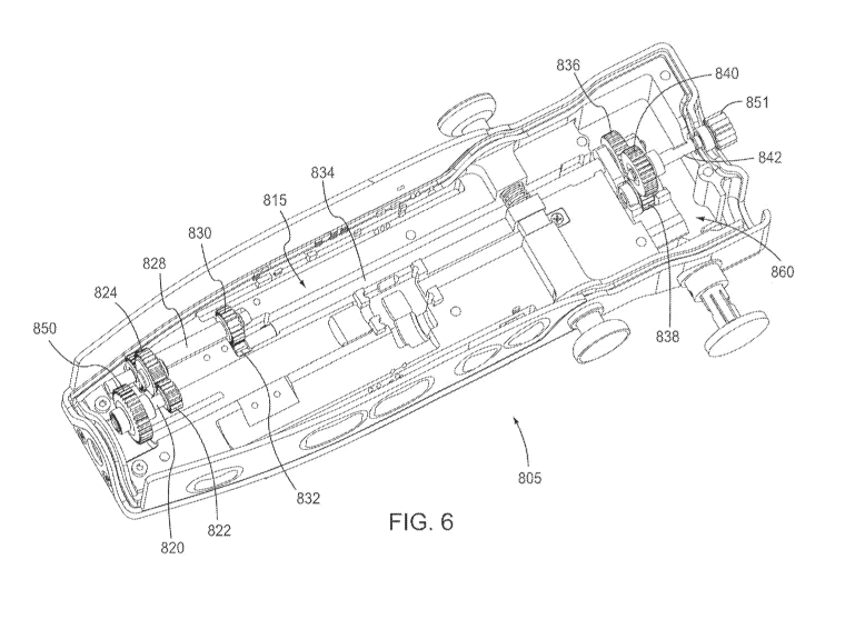
[0038] FIG. 5 shows an example holster 805 in accordance with aspects of
the present invention that allows for selective coupling of a thumbwheel of a
probe
with a holder drive gear. The holster 805 may be coupled with probe 105, with
a
probe as described in the '916 patent, the disclosure of which is incorporated
by
reference herein, or with any other suitable probe. Holster 805 comprises a
top
housing member 807, a bottom housing member 808, and a needle firing fork 890.
Needle firing fork 890 is positioned on the distal end of a needle firing
shaft 810,
which extends distally from holster 805. Holster 805 further comprises hook
members 814, which extend from top housing member 807, and which may
removably secure a probe to holster8.
[0039] Top housing member 807 further comprises a recess 804 exposing a
thumbwheel gear 850. Thumbwheel gear 850 is configured to mesh with
thumbwheel 60 when probe 105 is coupled with holster 805. In particular,
thumbwheel gear 850 is operable to rotate in response to manual rotation of
thumbwheel 60 when probe 105 is coupled with holster 805. A tissue sample
holder
drive gear 851 extends from a proximal end of holster 805. Gear 851 is
configured to
mesh with gear 170 of tissue sample holder 140. In particular, gear 851 is
operable
to rotate manifold 144 of tissue sample holder 140 when probe 105 is coupled
with
holster 805.
[0040] FIGS. 6 and 7 are perspective views of an example stereotactic 805
with components omitted to show an example linking mechanism and example
selective engagement mechanism. A linking mechanism 815 selectively links
thumbwheel gear 850 with gear 851. In particular, the linking mechanism 815,
having
a selective engagement mechanism 860, is configured to selectively cause gear
851
to rotate in response to rotation of thumbwheel gear 850. Linking mechanism
815 of
-11 -
CA 02887018 2015-04-07
WO 2014/084961 PCT/US2013/063079
this example comprises a shaft 820 extending proximally from thumbwheel gear
850.
Another gear 822 is fixed to shaft 820. Gear 822 thus rotates with shaft 820
and with
gear 850. Gear 822 also meshes with gear 824, which also meshes with gear 826.
Gear 826 thus rotates with gears 822, 824. A shaft 828 extends proximally from
gear
826. Another gear 830 is fixed to shaft 828. Gear 830 thus rotates with shaft
828 and
with gear 826. Gear 830 also meshes with gear 832. A shaft 834 extends
proximally
from gear 832. Another gear 836 is fixed to shaft 834. Gear 836 thus rotates
with
shaft 834 and with gears 830, 832. Gear 836 meshes with gear 838. Gear 838
selectively meshes with gear 840. When gear 838 is selected to mesh with gear
840,
gear 840 thus rotates with gears 836, 838. A shaft 842 connects gear 840 with
gear
851. Accordingly, when gear 838 is selected to mesh with gear 840, thumbwheel
gear 850 is coupled with gear 851 via gears 822, 824, 826, 830, 832, 836, 838,
840
and shafts 820, 828, 834, 842. However, when gear 838 is selected such that it
does not mesh with gear 840, thumbwheel gear 850 is not coupled with gear 851.
Accordingly, in the non-meshed configuration, motion of the thumbwheel 60 will
not
be linked to motion of the tissue sample holder 140 via the holder gear 851.
[0041] The selective meshing of the gear 838 with the gear 840 occurs by
actuating the selective engagement mechanism 860. As shown in FIGS. 6-8, the
selective engagement mechanism 860 may include a bracket 862 pivotally
connected to an end of the shaft 834. The bracket 862 may be attached to the
shaft
834 by passing the shaft 834 through receiving holes 866. A clip 868 may be
provided to ensure stable attachment of the bracket 862 to the shaft 834. The
bracket 862 includes a pair of troughs 864 adjacent to the gear 838 for
receiving a
pair of retaining features 870. The retaining features 870 and the gear 838
may be
attached to the shaft 872. The gear 838 may be located between the pair of
-12-
CA 02887018 2015-04-07
WO 2014/084961 PCT/US2013/063079
retaining features 870. The retaining features 870 rest within the troughs 864
but
may freely rotate along with the shaft 872 and the gear 838. Because gear 838
meshes with gear 836, rotation of the gear 836 causes the gear 838 to rotate.
The
selective engagement mechanism 860 further includes a plunger 878 having a
projection 876. The bracket includes a free end having a receiving portion 874
that
is matable with the plunger 878. As used herein, matable means that the
receiving
portion 874 and the plunger 878 each comprise a shape suitable to allow the
receiving portion 874 to mate with the plunger 878. For example, the receiving
portion 874 may be shaped to interact with the projection 876 of the plunger
878.
The selective engagement mechanism 860 may include a bracket biasing member
880 for biasing the bracket 862 into an engaged position. The plunger 878 may
include a plunger biasing member to bias the plunger 878 away from the bracket
862. In another aspect of the in .ntion, the bracket biasing member 880 is
sufficient
alone to bias the plunger projection 876 away from the bracket.
[0042] Operation of the selective engagement mechanism 860 will now be
described. As shown in FIG. 7, in the default position, the bracket biasing
member
880 biases the bracket 862 upwardly (i.e., in a direction toward the probe)
such that
the gear 838 is meshed with the gear 840. Also, as shown in FIG. 7, the
plunger 878
is fully retracted such that the plunger projection 876 is flush with the side
wall of the
holster 805. In this position, because the gear 838 is meshed with the gear
840,
movement of the thumbwheel 60 will transmit motion to the holder drive gear
851,
which in turn transmits motion to the tissue sample holder, in the manner
described
above. Thus, in the default position, the rotation of the thumbwheel is
directly linked
with the rotation of the sample holder. When the operator wishes to interrupt
the
linkage such that rotation of the thumbwheel is no longer linked with rotation
sample
-13-
CA 02887018 2015-04-07
WO 2014/084961 PCT/US2013/063079
holder, the operator pushes on the plunger 878. As the operator pushes on the
plunger 878, the plunger projection 876 moves away from the side wall of the
holster
and moves toward the receiving portion 874 of the bracket 862. This force may
include overcoming a plunger biasing mechanism that biases the plunger 878
toward
the retracted position. Once the plunger projection 876 contacts the
receiving
portion 874 the continued force against the bracket 862 imparts a downward
force
(i.e., away from the probe). For example, as shown in FIG. 7, the plunger
projection
876 and the bracket receiving portion 874 may be inclined such that the
forward
motion of the plunger 878 contacting the bracket receiving portion 874 imparts
the
downward force. Because one end of the bracket 862 is pivotally connected to
the
shaft 834, the downward force causes the bracket 862 to pivot about the shaft
834.
The retaining features 870, being disposed in the troughs 864 of the bracket
862,
along with the gear 838 being connected to the retaining features 870, also
move
with the pivoting of the bracket 862. Once the bracket 838 has been pivoted
the
gear 838 is no longer meshed with the gear 840. With the gears being in the
non-
meshed position, the thumbwheel 60 is no longer linked with the holder drive
gear
851 or the sample holder manifold 144. Thus, movement of the thumbwheel 60
will
not impart a rotational motion on the sample holder manifold 144. Similarly,
motor
rotation (discussed in detail below) of the tissue sample holder manifold 144
will not
impart rotational motion on the thumbwheel 60. Accordingly, the thumbwheel 60
can
be freely rotated without changing the compartment to which the sample will be
received and the tissue sample holder manifold 144 can be freely rotated
without
changing orientation of the thumbwheel 60 or needle 10. This position, where
the
plunger 878 is fully actuated, and the gear 838 is no longer meshed with gear
840 is
shown in FIG. 8.
- 14-
CA 02887018 2015-04-07
WO 2014/084961 PCT/US2013/063079
[0043] The plunger 878 may include a retaining mechanism 882 so that the
plunger 878 will remain in the depressed position even after the operator has
stopped applying force to the plunger 878. For example, the retaining
mechanism
882 may include a pin 884 and an L-shaped slot 886. After fully depressing the
plunger 878 the pin 884 will be located at the rear of the axial portion 888
of the L-
shaped slot 886 (e.g., where the axial portion 888 meets the circumferential
portion
890). Then, the operator may rotate the plunger 878 such that the pin 884 is
located
in the circumferential portion 890 of the L-shaped slot 886. Once located in
this
position, the pin 884 prevents any forward or backward movement of the plunger
878
until the operator rotates the plunger 878 back to the original position.
[0044] FIG. 9 shows another example selective engagement mechanism
960, in accordance with aspects of the present invention. The selective
engagement
mechanism 960 may include a bracket 962 slideably connected to an end of the
shaft 934. The bracket 962 may be attached to the shaft 934 by passing the
shaft
934 through receiving holes 966. The bracket 962 includes a pair of troughs
964
adjacent to the gear 938 for receiving a pair of retaining features 970. The
retaining
features 970 and gear 938 may be attached to the shaft 972. The gear 938 may
be
located between the pair of retaining features 970. The retaining features 970
rest
within the troughs 964 but may freely rotate along with the shaft 972 and the
gear
938. Because gear 938 meshes with gear 936, rotation of the gear 936 causes
the
gear 938 to rotate. The selective engagement mechanism 960 further includes a
plunger 978 having a projection 976. The bracket includes a free end having a
receiving portion 974, shaped to interact with the projection 976 of the
plunger 978.
The selective engagement mechanism 960 may include a bracket biasing member
980 for biasing the bracket 962 into an engaged position. As shown in FIG. 9,
the
-15-
CA 02887018 2015-04-07
WO 2014/084961
PCT/1JS2013/063079
biasing member 980 may surround the shaft 934 and abut a portion of the
bracket
962.
[0045] Operation of the selective engagement mechanism 960 will now be
described. The bracket biasing member 980 biases the bracket 962 forwardly
(i.e.,
in a direction toward the needle) such that the gear 938 is meshed with the
gear 940.
Also, as shown in FIG. 9, the plunger 978 is fully retracted such that the
plunger
projection 976 is flush with the side wall of the holster 905. In this
position, because
the gear 938 is meshed with the gear 940, movement of the thumbwheel 60 will
transmit motion to the tissue sample holder drive gear (not shown), which in
turn
transmits motion to the tissue sample holder, in the manner described above.
Thus,
in the default position, the rotation of the thumbwheel is directly linked
with the
rotation of the sample holder. When the operator wishes to interrupt the
linkage
such that rotation of the thumbwheel is no longer linked with for rotation of
the tissue
sample holder, the operator pushes on the plunger 978. As the operator pushes
on
the plunger 978, the plunger projection 976 moves away from the side wall of
the
holster and moves toward the receiving portion 974 of the bracket 962. This
force
may include overcoming a plunger biasing mechanism that biases the plunger 978
toward the retracted position. Once the plunger projection 976 contacts the
receiving portion 974 the continued force against the bracket 962 imparts a
rearward
force (i.e., away from the needle) to the bracket. For example, the plunger
projection
976 and the bracket receiving portion 974 may be inclined such that the
forward
motion of the plunger 978 contacting the bracket receiving portion 974 imparts
the
rearward force. Because one end of the bracket 962 is slideably associated
with the
shaft 934, the rearward force causes the bracket 962 to slide along the shaft
934 in
direction away from the needle. The retaining features 970, being disposed in
the
-16-
CA 02887018 2015-04-07
WO 2014/084961 PCT/US2013/063079
troughs 964 of the bracket 962, along with the gear 938 being connected to the
retaining features 970, also move with the sliding of the bracket 962. Once
the gear
938 has been translated toward the rear of the holster, the gear 938 is no
longer
meshed with the gears 940, 936. With the gears being in the non-meshed
position,
the thumbwheel 60 is no longer linked with the holder drive gear or the tissue
sample
holder manifold 144. Thus, movement of the thumbwheel 60 will not impart a
rotational motion on the tissue sample holder manifold 144. Similarly, motor
rotation
(discussed in detail below) of the tissue sample holder manifold 144 will not
impart
rotational motion on the thumbwheel 60. Accordingly, the thumbwheel 60 can be
freely rotated without changing the compartment to which the sample will be
received and the tissue sample holder manifold 144 can be freely rotated
without
changing orientation of the thumbwheel 60 or needle 10.
[0046] The plunger 978 may include a retaining mechanism 982 so that the
plunger 978 will remain in the depressed position even after the operator has
stopped applying force to the plunger 978. For example, the retaining
mechanism
982 may include a pin 984 and an L-shaped slot 986. After fully depressing the
plunger 978 the pin 984 will be located at the rear of the axial portion of
the L-shaped
slot 986 (e.g., where the axial portion meets the circumferential portion).
Then, the
operator may rotate the plunger 978 such that the pin 984 is located in the
circumferential portion of the L-shaped slot. Once located in this position,
the pin
984 prevents any forward or backward movement of the plunger 978 until the
operator rotates the plunger 978 back to the original position.
[0047] The selective engagement mechanism 860, 960 provides the
operator with the ability to select when the thumbwheel 60 should be linked to
the
tissue sample holder 140. This allows the operator the flexibility to have 1:1
linked
-17-
CA 02887018 2015-04-07
WO 2014/084961 PCT/US2013/063079
rotation of the thumbwheel 60 with the tissue sample holder manifold 144 and
when
desired, remove the linked rotation. For example, the operator can take
multiple
samples in the same tissue compartment (by disengaging the linkage while
continuing to take samples), or can return to a previous needle orientation,
without
rotating the tissue sample holder (by disengaging the linkage and then
rotating the
needle to a previous orientation). In another aspect, the operator can unlink
the
thumbwheel 60 from the tissue sample holder manifold 144 by depressing the
plunger 878, then rotating the tissue sample holder manifold 144 without
rotating the
needle 10 to inspect the quality of the sample within the tissue sample holder
manifold 144. The operator can then rotate the tissue sample holder manifold
144
back to the original (or any other position) while the plunger 878, 978
remains
depressed, and then allow the plunger 878 return to the unretracted position
to
reestablish the linkage.
[0048] As shown in FIG. 10, the tissue sample holder rotation may be
controlled by a motor 892, such as a piezoelectric motor, mounted in the
holster 805.
The motor 892 may have shaft 894 connected to a gear 896. The gear 896 meshes
with the gear 840. When the motor 892 is actuated, the shaft 894 rotates along
with
the gear 896. Because the gear 896 meshes with the gear 840, activation of the
motor 892 imparts rotation on the gear 840, causing rotation of the gear 851.
Thus,
when the probe is coupled with holster 805 to engage holder drive gear 851
with the
holder gear 170 and motor 892 is actuated, manifold 144 is rotated within
tissue
sample holder 140. When the selective engagement mechanism 860 is configured
such that gear 838 is meshed with the gear 840, activation of the motor 892
will
likewise cause rotation of the thumbwheel 60 and needle 10 through the linking
mechanism 815. Thus, through computer control of the motor 892, the rotation
of
- 18 -
CA 02887018 2015-04-07
WO 2014/084961 PCT/US2013/063079
the manifold 144 and the needle 10 may be fully automatically and
cooperatively.
When the selective engagement mechanism 860 is configured such that the gear
838 is not meshed with the gear 840, activation of the motor 892 will only
impart
rotation on the manifold 144, while the needle 10 will remain stationary,
unless
rotated separately via the thumbwheel 60. It should be understood that the
motor
may also be implemented in holster 905 in a similar manner as shown in FIG.
10.
[0049] Similarly, in an aspect of the present invention, actuation of the
selective engagement mechanism 860, 960 (i.e., the depression and/or rotation
of
the plunger 878, 978) may be performed via the computer controller. While not
shown, conventional methods of electromechanically depressing the plunger 878,
978 may be implemented. The software may allow the operator to actuate the
selective engagement mechanism 860, 960 by issuing a computer command.
Additionally, the software may be programmed to automatically actuate the
selective
engagement mechanism 860, 960 according predefined parameters. Accordingly,
by implementing computer software to control actuation of the motor 892, in
combination with selectively engaging and disengaging the linkage between the
thumbwheel 60 and the holder gear 851, a wide variety of sampling options are
available.
[0050] For example, in a first setting, the computer controller will maintain
selective engagement mechanism 860, 960 in a configuration where gear 838, 938
and the gear 840, 940 are meshed. In this setting, when the computer
controller
causes the motor to actuate, the rotation of the manifold 144 will match the
rotation
of the needle 1:1. This first setting would allow fully automatic sampling
where each
o'clock position of the needle 10 will automatically correspond with an
o'clock
-19-
CA 02887018 2015-04-07
WO 2014/084961 PCT/US2013/063079
position of the manifold. For example, at the one o'clock position of the
needle 10 a
sample will be taken and be stored in the one o'clock position of the
manifold.
[0051] As used herein, the "o'clock position" of the needle means the
orientation of the needle where the aperture of the needle is positioned to
take a
sample corresponding to the hour located on the face of an analog clock. For
example at the "twelve o'clock position" the aperture of the needle may be
facing
upwardly toward the patient's head. Then, when the needle is rotated clockwise
by
approximately 30 degrees from the "twelve o'clock position," the second
position
would be the "one o'clock" position. Each consecutive rotation of the needle
may
correspond to an o'clock position with 12 positions being defined within one
full
rotation of the needle. While the needle positions are generally referred to
herein as
o'clock position, it should be understood that any number of positions may be
defined by providing a smaller angle or greater angle between positions. For
example, if each consecutive position is defined by a 15 degree rotation, then
there
would be 24 consecutive positions around one full rotation of the needle.
Similarly, if
each consecutive position is defined by a 60 degrees rotation, there would be
6
consecutive positions within one full rotation of the needle. Furthermore, the
degree
of rotation between positions does not have to be uniform. For example, the
amount
of rotation between a first position and second position may be 15 degrees,
while the
amount of rotation between the second position and a third position may be 30
degrees. The manifold similarly may have a plurality of chambers having
"o'clock"
designation that correspond with the o'clock positions of the needle. For
example,
the chamber of the manifold designated as the 12 o'clock position would
correspond
to the 12 o'clock needle position. In this example, the needle aperture would
be
facing upward toward the head of the patient (i.e., the 12 o'clock position),
and the
- 20 -
CA 02887018 2015-04-07
WO 2014/084961 PCT/US2013/063079
chamber of the manifold positioned to receive the tissue taken from this
particular
needle position would be the 12 o'clock chamber. The manifold may have a
generally cylinder shape that is divided into a plurality of equally sized
chambers. As
the chambers correspond to the needle positions, the chambers may also be
designated by the same number of consecutive whole numbers. As with the needle
positions, the number of chambers in the manifold may be varied, but generally
match the number of needle positions. For example, if there are 24 defined
positions
of the needle, then the manifold may have 24 chambers.
[0052] As used herein, the "position of the manifold" means that the
particular tissue sample chamber associated with a given o'clock position is
aligned
with the sample tissue passageway to receive a vacuumed tissue sample. For
example, the "one o'clock position of the manifold" means that the tissue
sample
chamber associated with the one o'clock position is aligned with the sample
tissue
passageway and will receive the tissue sample once the vacuum is created. The
computer controller will then activate the motor to allow simultaneous
rotation of the
needle 10 and manifold 144 until both are in the two o'clock position. Next, a
new
sample will be taken. The process may continue automatically for as many
o'clock
(or other incremental steps) as necessary. Therefore, in this setting, samples
can be
taken automatically in sequential order (e.g., one o'clock, two o'clock, three
o'clock,
etc.)
[0053] In a second setting, where the computer controller also maintains
selective engagement mechanism 860, 960 in a configuration where gear 838, 938
and the gear 840, 940 are meshed, the computer controller may take samples at
particularly defined o'clock positions. For example, the operator may instruct
the
computer to take samples only at the odd o'clock intervals (e.g., 1, 3, 5,
etc), to take
- 21 -
CA 02887018 2015-04-07
WO 2014/084961 PCT/US2013/063079
samples only at the even o'clock intervals (e.g., 12, 2, 4, etc.), to take
samples first
at the odd o'clock intervals and then at the even o'clock intervals (e.g.,
first 1, 3, 5
etc. and then 12, 2, 4, etc.) or to take samples first at the even o'clock
intervals and
then at the odd o'clock intervals (e.g., first 12, 2, 4, etc. and then 1, 3,
5, etc.).
Because of the coupling of the rotation of the thumbwheel with the rotation of
the
manifold, the o'clock position of the needle 10 will always correspond to the
o'clock
position of the manifold, as the long as the selective engagement mechanism
860,
960 remain in the linked configuration.
[0054] In a third setting, the computer controller can selectively disengage
the gear 838, 938 from the gear 840, 940 as instructed by the software. This
will
allow for specific customization of which o'clock position of the needle 10
will
correspond to which o'clock position of the manifold 144. For example, the
operator
may instruct the computer via software to take samples only at the odd o'clock
positions (or just even, or odds then even, or even then odds) for the needle
10, but
to fill the manifold 144 in sequential order. In this example, if the first
sample is the
one o'clock needle 10 position, it would go in the one o'clock manifold 144
position.
The second needle 10 position would be the three o'clock (the next odd
o'clock),
while the manifold 144 would be in the two o'clock position. Similarly, the
third
needle 10 position would be in the five o'clock position, while the manifold
144 would
be in the three o'clock position, and so on.
[0055] The above operation can be controlled by the computer in several
ways. In a first method, starting from the one o'clock position of the needle
10 and
the manifold 144, a sample would be taken. Then the computer would actuate the
selective engagement mechanism 860, 960 to decouple the gear 838, 938 from the
gear 840, 940. While still decoupled, the computer controller would actuate
the
-22-
CA 02887018 2015-04-07
WO 2014/084961 PCT/US2013/063079
motor 892 which would cause only rotation of the manifold 144. The computer
controller will continue to rotate the manifold 144 until the two o'clock
position is
positioned two positions away from the position aligned with the tissue sample
passage. Once in position, the computer controller will stop activating the
motor 892
and will release the selective engagement mechanism 860, 960 to mesh the gear
838, 938 with gear 840, 940, thereby restoring the linkage between the needle
10
and the manifold 144. Next, the computer controller will reactivate the motor
892,
while rotating the needle 10 (thumbwheel 60) and the manifold 144
simultaneously.
After rotating the needle 10 and the manifold two o'clock positions, the
computer
controller will cease activation of the motor. Because the needle 10 was in
the one
o'clock position when the rotation started, it will end at the three o'clock
position.
Because the manifold 144 was two o'clock positions away from the tissue sample
passage, the two o'clock position of the manifold 144 will be aligned with
tissue
sample passage. Thus, when the vacuum begins, the needle 10 is at the three
o'clock position, while the manifold 144 is in the two o'clock position. The
above
steps can be repeated as necessary to place the tissue sample taken at the
five
o'clock needle 10 position into the three o'clock manifold chamber, the tissue
sample
taken at the seven o'clock position in the four o'clock manifold chamber, and
so on.
The same technique can be used to put any tissue sample of a given o'clock
needle
position into any desired o'clock manifold chamber.
[0056] Another method achieves the same result without any decoupling of
the gear 838, 938 from the gear 840, 940. The method involves first cutting
the
sample at the desired o'clock position of the needle 10, but before initiating
the
vacuum, rotating the needle 10 and manifold 144 together until the desired
manifold
144 position is acquired. For example, starting from the one o'clock position
of the
- 23 -
CA 02887018 2015-04-07
WO 2014/084961 PCT/US2013/063079
needle 10 and the one o'clock position of the manifold 144, it may be
desirable to
take a tissue sample at the three o'clock position of the needle 10 but insert
that
sample into the two o'clock chamber of the manifold 144. First, the computer
controller would activate the motor until both the needle 10 and the manifold
144 are
at the three o'clock position. After terminating the rotation, the cutter
would be
actuated to cut the sample. Next, before the vacuum is initiated, the computer
controller will activate the motor to cause both the needle 10 and the
manifold 144 to
rotate to the two o'clock position. Then, the vacuum is initiated, to bring
the already
cut tissue sample into the two o'clock chamber of the manifold 144. The above
steps can be repeated as necessary to place the tissue sample taken at the
five
o'clock needle 10 position into the three o'clock manifold chamber, the tissue
sample
taken at the seven o'clock position in the four o'clock manifold chamber, and
so on.
The same technique can be used to put any tissue sample of a given o'clock
needle
position into any desired o'clock manifold chamber.
[0057] In another aspect of the present invention a separate motor may
independently control the needle 10. The needle motor would likewise be
controlled
by the computer controller and would operate directly on the needle 10. When a
needle motor is present, the o'clock position of the needle 10 can be selected
independently of the o'clock position of the manifold 144. For example, when
it is
desirable to put the tissue sample taken at the three o'clock position in the
two
o'clock chamber of the manifold 144, the computer controller would first
decouple the
gear 838, 938 from the gear 840, 940 by actuating the selective engagement
mechanism 860, 960. Then, the computer controller would independently control
the
manifold motor 892 and the needle rotation motor until the needle 10 is in the
three
o'clock position and the manifold 144 is in the two o'clock position. The
above steps
- 24 -
CA 02887018 2015-04-07
WO 2014/084961 PCT/US2013/063079
can be repeated as necessary to place the tissue sample taken at the five
o'clock
needle 10 position into the three o'clock manifold chamber, the tissue sample
taken
at the seven o'clock position in the four o'clock manifold chamber, and so on.
The
same technique can be used to put any tissue sample of a given o'clock needle
10
position into any desired o'clock manifold chamber.
[0058] In another aspect of the present invention a combination of automatic
and manual actuation may be used to obtain the desired tissue sample in the
desired
manifold chamber. For example, when it is desirable to put the tissue sample
taken
at the three o'clock position in the two o'clock chamber of the manifold 144,
the
computer controller will first decouple the gear 838, 938 from the gear 840,
940 by
actuating the selective engagement mechanism 860, 960. Alternatively, the
operator
can manually disengage the gears by pressing and/or rotating the plunger 878,
978.
Once decoupled, the user can manually rotate the thumbwheel 60 until the
needle
is in the three o'clock position, while the computer controller will activate
the
motor to rotate the manifold 144 until it is in the two o'clock position.
Then, the
sample can be taken. The above steps can be repeated as necessary to place the
tissue sample taken at the five o'clock needle 10 position into the three
o'clock
manifold chamber, the tissue sample taken at the seven o'clock position in the
four
o'clock manifold chamber, and so on. The same technique can be used to put any
tissue sample of a given o'clock needle 10 position into any desired o'clock
manifold
chamber.
[0059] In another aspect of the present invention, the operator may wish to
rotate the manifold 144 so that collected tissue sample may be collected. To
do
this, the operator may manually (or automatically via the computer controller)
unlink
the thumbwheel 60 from the manifold 144 by depressing the plunger. Once
- 25 -
CA 02887018 2015-04-07
WO 2014/084961 PCT/US2013/063079
unlinked, the computer controller can activate the motor 892 to rotate the
manifold
144 until the particular o'clock position is viewable by the operator. After
the
inspection is completed, the computer controller will activate the motor to
either
return the sample chamber just viewed back to the previous position (or any
other
position). Once returned, the operator can allow the link between the
thumbwheel
and the manifold 144 to return by manually (or automatically via the computer
controller) allowing the plunger to retract.
[0060] An encoder 253, illustrated in FIG. 2, and described in detail in the
'687 patent, may be used in conjunction with the motor 892 and computer
controller
to sense rotational movement of the piezoelectric motor and to indirectly
measure
movement of the manifold 144 within the tissue sample holder.
[0061] In another aspect, the user may implement the above-described
functionality via a computer having a graphical user interface (GUI). For
example,
the user may select a configuration on the graphical user interface that
allows the
system to perform the above-described steps to deposit tissue into
programmable
chambers such that certain o'clock positions are skipped. For example, the GUI
may
be configured such that after receiving the user's input, the samples are
taken at
only odd o'clock positions and deposited in their corresponding manifold
chamber by
following the above-described steps or similar steps that provide the same
result. A
computer system and communication system, including computer logic, for
providing
the GUI and for implementing the user's instructions are discussed below. An
example GUI is disclosed in U.S. Provisional Application No. 61/682,418,
entitled
"BIOPSY SYSTEM WITH GRAPHICAL USER INTERFACE," filed on August 13,
2012, which is incorporated by reference herein.
- 26 -
CA 02887018 2015-04-07
WO 2014/084961 PCT/US2013/063079
[0062] In another aspect, the user would enable the configuration as per
above, but the system would deposit the samples in sequential chambers, such
that
odd numbered clock positions would be deposited in sequentially numbered
chambers."
[0063] In some variations, aspects of the present invention may be directed
toward one or more computer systems capable of carrying out the functionality
described herein. An example of such a computer system 1100 is shown in Fig.
11.
[0064] Computer system 1100 includes one or more processors, such as
processor 1104. The processor 1104 is connected to a communication
infrastructure
1106 (e.g., a communications bus, cross-over bar, or network). Various
software
aspects are described in terms of this example computer system. After reading
this
description, it will become apparent to a person skilled in the relevant
art(s) how to
implement the invention using other computer systems and/or architectures.
[0065] Computer system 1100 can include a display interface 1102 that
forwards graphics, text, and other data from the communication infrastructure
1106
(or from a frame buffer not shown) for display on a display unit 1130.
Computer
system 1100 also includes a main memory 1108, preferably random access memory
(RAM), and may also include a secondary memory 1110. The secondary memory
1110 may include, for example, a hard disk drive 1112 and/or a removable
storage
drive 1114, representing a floppy disk drive, a magnetic tape drive, an
optical disk
drive, etc. The removable storage drive 1114 reads from and/or writes to a
removable storage unit 1118 in a well-known manner. Removable storage unit
1118, represents a floppy disk, magnetic tape, optical disk, etc., which is
read by and
written to removable storage drive 1114. As will be appreciated, the removable
-27-
CA 02887018 2015-04-07
WO 2014/084961 PCT/US2013/063079
storage unit 1118 includes a computer usable storage medium having stored
therein
computer software and/or data.
[0066] In alternative aspects, secondary memory 1110 may include other
similar devices for allowing computer programs or other instructions to be
loaded into
computer system 1100. Such devices may include, for example, a removable
storage unit 1122 and an interface 1120. Examples of such may include a
program
cartridge and cartridge interface (such as that found in video game devices),
a
removable memory chip (such as an erasable programmable read only memory
(EPROM), or programmable read only memory (PROM)) and associated socket, and
other removable storage units 1122 and interfaces 1120, which allow software
and
data to be transferred from the removable storage unit 1122 to computer system
1100.
[0067] Computer system 1100 may also include a communications interface
1124. Communications interface 1124 allows software and data to be transferred
between computer system 1100 and external devices. Examples of communications
interface 1124 may include a modem, a network interface (such as an Ethernet
card), a communications port, a Personal Computer Memory Card International
Association (PCMCIA) slot and card, etc. Software and data transferred via
communications interface 1124 are in the form of signals 1128, which may be
electronic, electromagnetic, optical or other signals capable of being
received by
communications interface 1124. These signals 1128 are provided to
communications interface 1124 via a communications path (e.g., channel) 1126.
This path 1126 carries signals 1128 and may be implemented using wire or
cable,
fiber optics, a telephone line, a cellular link, a radio frequency (RF) link
and/or other
communications channels. In this document, the terms "computer program medium"
- 28 -
CA 02887018 2015-04-07
WO 2014/084961 PCT/1JS2013/063079
and "computer usable medium" are used to refer generally to media such as a
removable storage drive 1114, a hard disk installed in hard disk drive 1112,
and
signals 1128. These computer program products provide software to the computer
system 1100. The invention is directed to such computer program products.
[0068] Computer programs (also referred to as computer control logic) are
stored in main memory 1108 and/or secondary memory 1110. Computer programs
may also be received via communications interface 1124. Such computer
programs,
when executed, enable the computer system 1100 to perform the features of the
present invention, as discussed herein. In particular, the computer programs,
when
executed, enable the processor 1110 to perform the features of the present
invention. Accordingly, such computer programs represent controllers of the
computer system 1100.
[0069] In an aspect where the invention is implemented using software, the
software may be stored in a computer program product and loaded into computer
system 1100 using removable storage drive 1114, hard drive 1112, or
communications interface 1120. The control logic (software), when executed by
the
processor 1104, causes the processor 1104 to perform the functions of the
invention
as described herein. In another aspect, the invention is implemented primarily
in
hardware using, for example, hardware components, such as application specific
integrated circuits (ASICs). Implementation of the hardware state machine so
as to
perform the functions described herein will be apparent to persons skilled in
the
relevant art(s).
[0070] In yet another aspect, the invention is implemented using a
combination of both hardware and software.
- 29 -
CA 02887018 2015-04-07
WO 2014/084961 PCT/US2013/063079
[00711 Fig. 12 shows a communication system 1200 involving use of various
features in accordance with aspects of the present invention. The
communication
system 1200 includes one or more assessors 1260, 1262 (also referred to
interchangeably herein as one or more "users") and one or more terminals 1242,
1266 accessible by the one or more accessor 1260, 1262. In one aspect,
operations
in accordance with aspects of the present invention is, for example, input
and/or
accessed by an accessor 1260 via terminal 1242, such as personal computers
(PCs), minicomputers, mainframe computers, microcomputers, telephonic devices,
or wireless devices, such as personal digital assistants ("PDAs") or a hand-
held
wireless devices coupled to a remote device 1243, such as a server, PC,
minicomputer, mainframe computer, microcomputer, or other device having a
processor and a repository for data and/or connection to a repository for
data, via, for
example, a network 1244, such as the Internet or an intranet, and couplings
1245,
1264. The couplings 1245, 1264 include, for example, wired, wireless, or
fiberoptic
links. In another aspect, the method and system of the present invention
operate in
a stand-alone environment, such as on a single terminal. The communication
system may include the graphical user interface disclosed in U.S. Provisional
Application No. 61/682,418, entitled "BIOPSY SYSTEM WITH GRAPHICAL USER
INTERFACE," filed on August 13, 2012, which is incorporated by reference
herein.
[0072] While this invention has been described in conjunction with the
example aspects outlined above, various alternatives, modifications,
variations,
improvements, and/or substantial equivalents, whether known or that are or may
be
presently unforeseen, may become apparent to those having at least ordinary
skill in
the art. Accordingly, the example aspects of the invention, as set forth
above, are
intended to be illustrative, not limiting. Various changes may be made without
- 30 -
CA 02887018 2015-04-07
WO 2014/084961 PCT/US2013/063079
departing from the spirit and scope of the invention. Therefore, the invention
is
intended to embrace all known or later-developed alternatives, modifications,
variations, improvements, and/or substantial equivalents.
- 31 -