Note: Descriptions are shown in the official language in which they were submitted.
CA 2887148 2017-05-04
ABRASIVE ARTICLE INCORPORATING AN INFILTRATED ABRASIVE
SEGMENT
This patent application is a divisional of Canadian Patent Application No.
2,785,572 filed December 31, 2010.
TECHNICAL FIELD
The following is generally directed to abrasive tools and processes for
forming
same, and more particularly, to abrasive tools utilizing infiltrated abrasive
segments
attached to a base and methods of assembling such tools.
to BACKGROUND ART
Tools necessary for furthering infrastructure improvements, such as building
additional roads and buildings, are vital to the continued economic expansion
of
developing regions. Additionally, developed regions have a continuing need to
replacing aging infrastructure with new and expanded roads and buildings.
The construction industry utilizes a variety of tools for cutting and grinding
of
construction materials. Cutting and grinding tools are required for to remove
or
refinish old sections of roads. Additionally, quarrying and preparing
finishing
materials, such as stone slabs used for floors and building facades, require
tools for
drilling, cutting, and polishing. Typically, these tools include abrasive
members
bonded to a base element, such as a plate or a wheel. Breakage of the bond
between
the abrasive member and the base element can require replacing the abrasive
member
and/or the base element, resulting in down time and lost productivity.
Additionally,
the breakage can pose a safety hazard when portions of the abrasive member are
ejected at high speed from the work area. As such, improved bonding between
the
abrasive member and the base element is desired.
DISCLOSURE OF INVENTION
According to one aspect of the present invention there is provided An abrasive
article comprising: a base; an abrasive member including abrasive particles
bound to a
metal matrix, the abrasive member further comprising a network of
interconnected
- 1 -
CA 2887148 2017-05-04
pores substantially filled with an infiltrant comprising a metal infiltrant
material; a
backing region between the abrasive member and the base, the backing region
comprising a network of interconnected pores substantially filled with an
infiltrant
comprising a metal infiltrant material, the backing region being a region
distinct from
the base and a region distinct from the abrasive member; and a welding joint
at the
backing region bonding the base and the abrasive member together, wherein the
metal
infiltrant material of the abrasive member is the same metal infiltrant
material of the
backing region, wherein the metal infiltrant material comprises a bronzing
material,
and wherein the bronzing material comprises a metal alloy including copper and
tin.
BRIEF DESCRIPTION OF THE DRAWINGS
The present disclosure may be better understood, and its numerous features and
advantages made apparent to those skilled in the art by referencing the
accompanying
drawings.
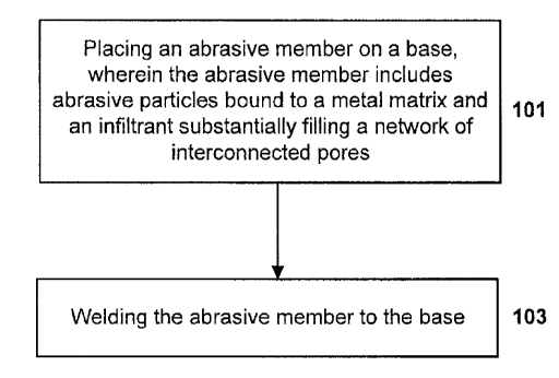
FIG. 1 includes a flow chart of a method of forming an abrasive article in
accordance with an embodiment.
FIG. 2 includes an illustration of an abrasive article in accordance with an
embodiment.
FIGs. 3A and 3B include cross-sectional images of portion of an abrasive
article including a portion of a backing region in accordance with an
embodiment.
FIG. 4 includes a cross-sectional image of a conventional hot pressed abrasive
article having a backing region exhibiting stones.
The use of the same reference symbols in different drawings indicates similar
or
identical items.
DESCRIPTION OF THE PREFERRED EMBODIMENT(S)
According to an embodiment, the abrasive articles herein can include a base
element and an abrasive member. The abrasive article can be a cutting tool for
cutting
construction materials, such as a saw for cutting concrete. Alternatively, the
abrasive
- 2 -
CA 2887148 2017-05-04
article can be a grinding tool such as for grinding concrete or fired clay or
removing
asphalt.
FIG. 1 includes a flow chart providing a method of forming an abrasive article
according to an embodiment. As illustrated, the process can be initiated at
step 101
- 2a -
CA 02887148 2015-04-01
by placing an abrasive member on a base. It will be appreciated that the
abrasive
member can be initially formed before being placed on the base for attachment.
In
particular, the abrasive member can be an infiltrated abrasive segment having
abrasive
particles bound to a metal matrix, and further comprising a network of
interconnected
pores, wherein at least a portion of the pores are filled with an infiltrant
made of a
metal infiltrant material.
The base element can be in the form of a ring, a ring section, a plate, or a
disc
depending upon the intended application of the abrasive article. The base
element can
be made of a metal or metal alloy. For instance, the base can be made of a
steel, and
particularly, a heat treatable steel alloys, such as 25CrMo4, 75Cr1, C60, or
similar
steel alloys for base elements with thin cross sections or simple construction
steel like
St 60 or similar for thick base elements. The base element can have a tensile
strength
of at least about 600 N/mm2. The base element can be formed by a variety of
metallurgical techniques known in the art.
Notably. the base material can be a low-carbon type material, which will
facilitate a welding process according to embodiments herein. The base
material can
have less than about 10% carbon content, such as less than about 8%, less than
about
6%, less than about 4%, less than about 2%, and even less than about 1%, to
facilitate
the forming process.
In an exemplary embodiment, an abrasive member includes abrasive particles
embedded in a metal matrix having a network of interconnected pores. The
abrasive
particles can include an abrasive material having a Mobs hardness of at least
about 7.
In particular instances, the abrasive particles can include a superabrasive
material,
such as diamond or cubic boron nitride. The abrasive particles can have a
particle
size of not less than about 400 US mesh, such as not less than about 100 US
mesh,
such as between about 25 and 80 US mesh. Depending on the application, the
size
can be between about 30 and 60 US mesh.
The abrasive particles can be present in an amount between about 2 vol% to
about 50 vol%. Additionally, the amount of abrasive particles may depend on
the
application. For example, an abrasive member for a grinding or polishing tool
can
include between about 3.75 vol% and about 50 vol% abrasive particles of the
total
- 3 -
CA 02887148 2015-04-01
volume of the abrasive member. Alternatively, an abrasive member for a cutting-
off
tool can include between about 2 vol% and about 6.25 vol% abrasive particles
of the
total volume of the abrasive member. Further, an abrasive member for core
drilling
can include between about 6.25 vol% and about 20 vol% abrasive particles of
the total
volume of the abrasive member.
The metal matrix can include a metal element or metal alloy including a
plurality of metal elements. For certain abrasive segments, the metal matrix
can
include metal elements such as iron, tungsten, cobalt, nickel, chromium,
titanium,
silver, and a combination thereof. In particular instances, the metal matrix
can
include a rare earth element such as cerium, lanthanum, neodymium, and a
combination thereof.
In one particular example, the metal matrix can include a wear resistant
component. For example, in one embodiment, the metal matrix can include
tungsten
carbide, and more particularly, may consist essentially of tungsten carbide.
In certain designs, the metal matrix can include particles of individual
components or pre-alloyed particles. The particles can be between about 1.0
micron
and about 250 microns.
As noted above, the abrasive member can be formed such that an infiltrant is
present within the interconnected network of pores within the body of the
abrasive
member. The infiltrant can partially fill, substantially fill, or even
completely fill the
volume of the pores extending through the volume of the abrasive member. In
accordance with one particular design, the infiltrant can be a metal or metal
alloy
material. For example, some suitable metal elements can include copper, tin,
zinc,
and a combination thereof.
In particular instances, the infiltrant can be a bronzing material made of a
metal
alloy, and particular a copper-tin metal alloy, such that it is particularly
suited for
welding according to embodiments herein. For example, the bronzing material
can
consist essentially of copper and tin. Certain bronzing materials can
incorporate
particular contents of tin, such as not greater than about 20%, not greater
than about
15%, not greater than about 12%, or even not greater than about 10% of the
total
amount of materials within the composition. In accordance with an embodiment.
the
- 4 -
-
CA 02887148 2015-04-01
bronzing material can include an amount of tin within a range between about 5%
and
about 20%, such as between about 8% and about 15%, or even between about 8%
and
about 12%.
Moreover, certain bronzing materials can be used as infiltrant material, and
can
have an amount of copper of at least about 80%, at least about 85%, or even at
least
about 88% of the total amount of materials within the composition. Some
bronzing
materials can utilize an amount of copper within a range between about 80% and
about 95%, such as between about 85% and about 95%, or even between about 88%
and about 93%.
Additionally, the bronzing material may contain a particularly low content of
other elements, such as zinc to facilitate proper formation of the abrasive
article
according to the forming methods of the embodiments herein. For example, the
bronzing material may utilize not greater than about 10%, such as not greater
than
about 5%, or even not greater than about 2% zinc. In fact, certain bronzing
materials
can be essentially free of zinc.
The abrasive member may be manufactured, such that abrasive particles can be
combined with a metal matrix to form a mixture. The metal matrix can include a
blend of particles of the components of the metal matrix or can be pre-alloyed
particles of the metal matrix. In an embodiment, the metal matrix can conform
to the
formula (WC),,WxFeyCr,X( 1 -w-x-y-z). wherein 0<w<0.8, 0<x<0.7, 0<y<0.8,
0<z<0.05,
w+x+y+z<1, and X can include other metals such as cobalt and nickel. In
another
embodiment, the metal matrix can conform to the formula (WC)õWõFeyCrzAg,X0,-,-
x-y-z), wherein 0<w<0.5, 0<x<0.4, 0<y<1.0, 0<z<0.05, 0<v<0.1, v+w+x+y+z<1, and
X
can include other metals such as cobalt and nickel.
The mixture of metal matrix and abrasive particles can be formed into an
abrasive preform by a pressing operation, particularly a cold pressing
operation, to
form a porous abrasive member. The cold pressing can be carried out at a
pressure of
between about 50 kN/cm2 (500 MPa) to about 250 kN/cm2 (2500 MPa). The
resulting
porous abrasive member can have a network of interconnected pores. In an
example,
the porous abrasive member can have a porosity between about 25 and 50 vol%.
- 5 -
CA 02887148 2015-04-01
The resulting porous abrasive member can then be subject to an infiltration
process, wherein the infiltrant material is disposed within the body of the
abrasive
member, and particularly, disposed within the interconnected network of pores
within
the body of the abrasive member. The infiltrant may be drawn into the pores of
the
cold pressed abrasive member via capillary action. After the infiltration
process, the
resulting densified abrasive member can be not less than about 96% dense. The
amount of infiltrant that infiltrates the abrasive member can be between about
20 wt%
and 45 wt% of the densified abrasive member.
The abrasive member can include a backing region, disposed between the
abrasive member and the base, which facilitates the joining of the abrasive
member
and the base. According to one embodiment, the backing region can be a
distinct
region from the abrasive member and the base. Still, the backing region can be
initially formed as part of the abrasive member, and particularly may be a
distinct
region of the abrasive member that has particular characteristics facilitating
the
joining of the abrasive member and the base. For example, according to one
embodiment, the backing region can have a lesser percentage (vol%) of abrasive
particles as compared to the amount of abrasive particles within the abrasive
member.
In fact, in certain instances, the backing region can be essentially free of
abrasive
particles. This may be particularly suitable for forming methods utilizing a
beam of
energy (e.g., a laser) used to weld the abrasive member to the base.
At least a portion of the backing region can include a bonding composition.
The bonding composition can include a metal or metal alloy. Some suitable
metal
materials can include transition metal elements, including for example,
titanium,
silver, manganese, phosphorus, aluminum, magnesium, chromium, iron, lead,
copper,
tin, and a combination thereof.
In particular instances, the bonding composition can be similar to the
infiltrant,
such that the bonding composition and the infiltrant are different from each
other by
not greater than a single elemental species. In even more particular
instances, the
bonding composition can be the same as the infiltrant. For example, the
bonding
composition can be a bronzing material, and more particularly, can consist
essentially
of a bronzing material as described herein.
- 6 -
CA 02887148 2015-04-01
According to embodiments herein, the bonding composition can be related to
the infiltrant composition in having a certain degree of commonality of
elemental
species. Quantitatively, an elemental weight percent difference between the
bonding
composition and the infiltrant composition may not be greater than about 20
wt%.
Elemental weight percent difference is defined as the absolute value of the
difference
in weight content of each element contained in the bonding composition
relative to the
infiltrant composition. Other embodiments have closer compositional
relationships
between the bonding composition and the composition of the infiltrant. The
elemental
weight percent difference between the bonding composition and the infiltrant
composition may, for example, not exceed 15 wt%, 10 wt%, 5 wt%, or may not
exceed 2 wt%. An elemental weight percent difference of about zero represents
the
same composition making up the backing region and the infiltrant. The
foregoing
elemental values may be measured by any suitable analytical means, including
microprobe elemental analysis, and ignores alloying that might take place
along areas
in which the infiltrant contacts the metal matrix.
The backing region can have a particular content of porosity. For example, the
backing region can have a porosity that is less than the porosity of the
abrasive
member. In fact, the amount of porosity in the backing region can be
significantly
less as compared to the amount of porosity within the abrasive member. In some
cases, the backing region comprises at least 2% less porosity as compared on a
volume percent basis between the two regions. In other instances, the
difference can
be greater, such as at least about 4% less porosity, at least about 5% less,
at least
about 7% less, at least about 10% less, or even at least about 15% less
porosity than
the abrasive member. The difference in porosity can facilitate proper
infiltration of
the backing region and abrasive member.
The backing region can have not greater than about 40 vol% porosity for the
total volume of the backing region. In other instances, the amount of porosity
within
the backing region can be not greater than about 38 vol%, not greater than
about 34
vol% or even not greater than about 30 vol%. Still, the amount of porosity
within the
backing region can be at least about 7 vol%, at least about 8 vol%, at least
about 10
vol%, at least about 12 vol%, or even at least about 15 vol% infiltrant. The
porosity
- 7 -
CA 02887148 2015-04-01
content of the backing region can be within a range between any of the minimum
and
maximum percentages noted above.
It will further be appreciated that a significant portion of the total
porosity
within the backing region can be interconnected porosity. That is, at least a
majority,
or even at least about 75%, at least about 80%, at least about 90%, at least
about 95%,
or essentially all of the porosity can be interconnected porosity.
The backing region can include at least about 5 vol% infiltrant for the total
volume of the backing region. In other instances, the backing region can
include at
least about 7 vol%, at least about 8 vol%, at least about 10 vol%, at least
about 12
vol%, or even at least about 15 vol% infiltrant. Still, the amount of
infiltrant can be
limited, such that it is not greater than about 40 vol%, not greater than
about 38 vol%,
not greater than about 34 vol% or even not greater than about 30 vol%. The
amount
of infiltrant can be within a range between any of the minimum and maximum
percentages noted above.
Accordingly, the backing region can include a network of interconnected pores
formed between a matrix metal, and wherein the infiltrant material
substantially fills
the interconnected pores. The backing region can contain similar amounts of
matrix
metal and infiltrant. Notably, the backing region may be essentially free of
abrasive
particles. In such embodiments wherein the backing region includes
interconnected
pores substantially filled with the infiltrant, the infiltrant material can
act as a
bronzing material in forming a joint (e.g., a welded joint) between the base
and the
abrasive member.
Accordingly, the formation the backing region, and particularly, control of
the
nature and size of porosity within the backing region can be controlled to
facilitate
proper infiltration. Proper infiltration ensures proper material
characteristics of the
backing region and formation of a suitable welding joint region between the
backing
region and the base. For example, the backing region is formed such that the
average
pore size of the pores within the backing region are not greater in size, and
more
particularly smaller in size, than the average pore size of the pores within
the abrasive
member. Such a distinction can facilitate full and proper infiltration of the
backing
region and formation of a strong welding joint region.
- 8 -
CA 02887148 2015-04-01
In certain instances, the average pore size of the pores within the backing
region
is at least about 1% smaller than the average pores size of the pores within
the
abrasive member. In other embodiments, the difference in average pore size can
be
greater, such as at least about 3%, at least about 5%, at least about 10%, or
even at
least about 20% smaller. Still, the difference can be limited, such that it is
not greater
than about 80%, not greater than about 70%, not greater than about 50%, or
even not
greater than about 40%. The difference in average pore size can be within a
range
between any of the minimum and maximum values.
Control of the nature and size of the porosity within the abrasive member and
the backing region can include the application of highly uniform application
of
pressure during formation of the abrasive article including the abrasive
member and
the backing region. The uniform pressure across the entire length and volume
of the
two components can facilitate homogenous compression of the bodies and
substantially uniform pore sizes. Powder sizes of the powder material used to
form
the abrasive member and backing region may be particularly selected to further
control the pore size.
In one embodiment, the backing region can include a particular bronzing
material that facilitates a welding operation to join the abrasive member and
the base.
In fact, certain backing regions can consist essentially of a copper-tin
bronzing
material. Some suitable bronzing materials can include at least about 80%
copper,
such as at least about 82% copper, at least about 85% copper, at least about
87%
copper, at least about 88% copper, at least about 90% copper, at least about
93%
copper, or even at least about 95% copper. As such, the bronzing material can
include
a balance amount of tin, such that suitable bronzing materials can include not
greater
than about 20% tin, not greater than about 18% tin, not greater than about 15%
tin, not
greater than about 13% tin, not greater than about 12% tin, not greater than
about 10%
tin, not greater than about 8% tin, not greater than about 5% tin.
After placing the abrasive member on the base at step 101, the process can
continue at step 103 by welding the abrasive member to the base. In particular
instances the welding process includes impinging a beam of energy at the base,
and
more particularly, can include impinging a beam of energy at the backing
region
between the abrasive member and the base. In particular instances, the beam of
- 9 -
CA 02887148 2015-04-01
energy can be a laser, such that the abrasive segment is attached to the base
via a laser
welded bond joint. The laser may be a Roffin laser source commonly available
from
Dr. Fritsch.
FIG. 2 illustrates an exemplary abrasive article 200 including a densified
abrasive member 202 bonded to a base 204. The densified abrasive member 202
includes metal matrix particles 206 and abrasive particles 208 bonded to each
other,
and an interconnected network of pores extending between the metal matrix
particles
206 that is filled with an infiltrant 210. As further illustrated, the
abrasive article can
include a backing region 212 disposed between the abrasive member 202 and the
base
204. The backing region 212 can include a bonding composition that can be
continuous with the composition of the densified abrasive member 202.
In accordance with one embodiment, the backing region of the abrasive article
is formed such that the backing region 212 can include a first phase and a
second
phase uniformly distributed within each other. F1Gs. 3A and 3B include cross-
sectional images of portion of an abrasive article including a portion of a
backing
region in accordance with an embodiment. As illustrated, the image of FIG. 3A
includes a portion of a base 301, a portion of a backing region 302, and a
portion of an
abrasive segment 303. As further illustrated in FIG. 3B, the backing region
302 can
include discrete phases, particularly a first phase 305 and a second phase 306
that are
substantially uniformly intermixed.
Moreover, the first phase 305 and the second phase 306 can have discrete
regions as illustrated in the magnified image. The discrete regions can be
polycrystalline regions that have an average size of not greater than about 50
microns
as measured along the longest dimension in a similiary magnified image. This
may be
facilitated by the use of a metal material having a particular average powder
size and
having a substantially spherical shape. In certain embodiments, the discrete
regions
of the first and second phases 305 and 306 can be smaller, such as on the
order of not
greater than about 40 microns, not greater than about 30 microns, not greater
than
about 25 microns, or even not greater than about 20 microns. In particular
instances,
the discrete regions of the first and second phases 305 and 306 can have an
average
size within a range between about 1 micron and about 50 microns, such as
between
-10-
CA 02887148 2015-04-01
about 5 microns and about 50 microns, such as between about 10 microns and
about
40 microns, or even between about 10 microns and about 30 microns.
As illustrated, the first and second phases 305 and 306 can be finely
intermixed
with each other and finely marbled. Moreover, the distinct regions identifying
the
first phase 305 can be defined by an elongated, fibrous, and/or dendritic
morphology,
wherein fibrous strands can extend through the second phase 306 and even
become
intertwined with each other.
Additionally, the backing region 302 can include fine closed pores 307, which
may be uniformly spaced apart from each other throughout the entire volume of
the
DJ backing region 302. In particular instances, the closed pores 307 can
have particularly
rounded shapes, and generally, the average pore size is less than about 50
microns,
such as less than about 40 microns, less than about 25 microns, or even less
than
about 15 microns.
The backing region can have an average thickness of not greater than about 400
microns, such as on the order of not greater than about 300 microns, not
greater than
about 200 microns. The average backing region may be measured by taking at
least
about 10 different measurements using magnified images such as illustrated in
FIG.
3A along a length of the interface of the backing region and abrasive member
of at
least about 1 mm. In other instances, the backing region 302 can be formed to
have
an average thickness of at least about 50 microns, such as at least about 100
microns,
at least about 150 micron, or even at least about 175 microns. Still,
particular designs
may utilize a backing region having an average thickness within a range
between
about 50 microns and about 400 microns, such as between about 100 microns and
about 300 microns.
Moreover, the backing region 302 can be essentially free of stones, which may
be common in more conventional abrasive articles (e.g., hot pressed abrasive
segments bonded to the base via welding). Stones are generally identified as
regions
of non-homogenous composition as compared to the surrounding region, and can
present regions that are more prone to induce failure of fracture through the
region.
FIG. 4 includes a cross-sectional image of a conventional abrasive article
having a
backing region 401 exhibiting stones 403, which are present as large and
rounded
-11-
CA 02887148 2015-04-01
particles that are surrounded by a distinct, second phase 404. Moreover, the
backing
region 401 exhibits pores 405 that are not uniformly dispersed throughout the
volume
of the backing region, but are concentrated in particular regions, such as in
regions
proximate to the stones 403, and even more particularly, at the interfaces
between the
stones 403 and the distinct second phase 404 surrounding the stones 403.
Abrasive article formed according to embodiments herein may have particular
mechanical characteristics, and particularly suitable strength of bonds and
consistency
in the strength of bonds between the abrasive segment and the base as measured
at the
backing region. For example, according to one embodiment, the abrasive article
can
have an average break strength at the backing region of at least about 600
N/mm2,
which can be measured according to European standard testing procedures
outlined in
EN13236. In certain instances, the average break strength can be at least
about 600
N/mm2, such as at least about 700 N/mm2, at least about 800 N/mm2, at least
about
925 N/mm2, such as at least about 950 N/mm2, or even at least about 975 N/mm2.
In
still more particular embodiments, the abrasive article can have an average
break
strength within a range between about 600 N/mm2 and about 1400 N/mm2, between
about 700 N/mm2 and about 1400 N/mm2, and even between about 800 N/mm2 and
about 1400 N/mm2. In certain embodiments, the abrasive article can have an
average
break strength with a range between about 900 N/mm2 and about 1400 N/mm2, such
as between about 925 N/mm2 and about 1350 N/mm2, between about 950 N/mm2 and
about 1300 N/mm2, or even between about 975 N/mm2 and about 1250 N/mm2.
Moreover, the abrasive articles of embodiments herein can exhibit consistent
break strength as measured by the break strength variation, which is
calculated as the
standard deviation of at least 100 measurements. The abrasive articles of the
embodiments herein can have a break strength variation of not greater than
about 150,
such as not greater than about 125, not greater than about 120, or even not
greater
than about 110. In certain instances, the break strength variation can be
within a
range between about 25 and about 150, such as between about 25 and about 125,
or
even between about 25 and about 110.
The abrasive articles of embodiments herein can have certain performance
features. For example, the abrasive articles can have an average cut speed of
at least
about 1000 cm2/min for 50 cuts through a paving slabs made of concrete
aggregate
- 12 -
CA 02887148 2015-04-01
used in paving roads and having a thickness of 4 cm and a length of 30 cm. In
fact,
certain abrasive articles can have an average cut speed of at least about 1050
cm2/min,
such as at least about 1100 cm2/min, or even at least about 1125 cm2/min.
Particular
embodiments herein may utilize and abrasive article having an average cut
speed
within a range between about 1000 cm2/min and about 1400 cm2/min, such as
between about 1050 em2/min and about 1400 cm2/min, or even between about 1100
cm2/min and about 1300 cm2/min.
Examples
Four samples are formed and tested. Sample 1 is an infiltrated part formed
initially through cold pressing at approximately 1000 MPa, and thereafter
infiltrated
with a particular bronze material. The abrasive member includes a tungsten
carbide-
based metal matrix (may include other metals of cobalt and nickel) and
abrasive
particles of diamond. The abrasive article of sample 1 also includes a backing
region
that is essentially free of abrasive particles. The infiltrant is a 80/20
copper/tin bronze
material having an average particle size of less than about 45 microns.
Sample 2 is formed according to the process of sample 1, except that the
bronze
material is a 85/15 copper/tin bronze material having an average particle size
of less
than 63 microns.
Sample 3 is formed according to the process of sample 1, except that the
bronze
material is a 90/10 copper/tin bronze material having an average particle size
of less
than 45 microns.
Sample 4 is formed according to the process of sample 1, except that the
bronze
material is a 95/5 copper/tin bronze material having an average particle size
of less
than 74 microns.
Speed and life tests were conducted on Samples 1-4, the results of which are
summarized in Table 1 below.
Table 1
Sample Sample Sample Sample
1 2 3 4
Speed 960 1029 864 900
- 13 -
CA 02887148 2015-04-01
(cm2imin)
Life (m2/mm) 0.387 0.492 0.527 0.373
As noted above, the speed of cutting and life of the abrasive articles formed
according to samples 1-4 demonstrated industry standard capabilities. The
speed for
samples 1-4 was greater than certain conventional industry standard hot
pressed
pieces. The life was also improved as compared to certain conventional
articles.
Furthermore, many parts were formed according to the samples above (Samples
1-4). In fact, 16 segments were formed for each of the samples (i.e., samples
1-4),
which were laser welded to low carbon steel. The welding strength of each of
the
samples, and the average break strength and standard deviation are provided
below in
Table 2, based on the measured torque necessary to break the segment from the
base.
lo Table 2
Sample Sample Sample Sample
1 2 3 4
Average (N m) 21.7 20.5 22.9 19.6
Standard
1.75 1.71 0.83 1.93
Deviation
As can be seen, the segments for samples 1-4 demonstrated suitable average
break strength for industry use. Perhaps more remarkable, is that the standard
deviation for all samples tested was significantly low, particularly as
compared to
conventional parts, wherein the standard deviations are typically much higher.
Sample 5 and 6 are formed according to the embodiment of sample 2 above.
Samples 5 and 6 each include 16 independent cold pressed and infiltrated
segments
that are laser welded to a low-carbon steel base. The average break strength
and
break strength variation are measured for each of the 16 segments for samples
5 and
6. The results are summarized below.
- 14 -
CA 02887148 2015-04-01
Table 3
Sample Sample
6
Average (N/mm2) 998 1131
Break Strength
Variation 75.7 106.5
The average break strength recorded for sample 5 and 6 meets industry
standards. More particularly, the break strength variation is better than
other
conventional samples, which were tested and typically had values of greater
than 120,
5 if not 150. Clearly, the combination of laser welding and infiltrated
abrasive articles
facilitates a strongly bonded article, having a more consistent joint
interface at the
base, leading to fewer catastrophic failures and breakage of abrasive segments
bonded
to the base.
According to an embodiment, the abrasive tool includes a carrier element and
an abrasive component. The abrasive tool can be a cutting tool for cutting
construction materials, such as a saw for cutting concrete. Alternatively, the
abrasive
tool can be a grinding tool such as for grinding concrete or fired clay or
removing
asphalt. In particular, the following embodiments have formulated a method for
the
welding of infiltrated abrasive segments onto a base for use in an abrasive
article.
Certain references in the art have generally recognized welding as a suitable
joining
process. Some references have even made grand statements that an infiltrated
piece
may be joined to a base by a variety of processes, and randomly list welding
as one of
many processes. However, these references are not even remotely directed to
welding
of infiltrated pieces and such a process or article is not enabled by the
references. The
inventors of the present application, as experts in the field, note that
welding of
infiltrated articles is not a trivial process. Moreover, based on their
knowledge, no
article in the industry is based on successfully welded infiltrated parts.
With the
success of the abrasive article demonstrated by the Applicants, industry
demand for
such an article has grown. Moreover, certain problems needed to be identified
and
overcome in order to form a commercially successful product according to the
embodiments herein. Certain combination of features lending to this success
include
the size and shape of the raw materials used to form the backing region, the
composition of the backing region, the type, wavelength, and power of beam
used for
- 15-
CA 02887148 2015-04-01
welding, the type and positioning of abrasive grains within the abrasive
segment.
Moreover, the abrasive segments of the embodiments herein demonstrated
unexpected
mechanical characteristics and performance properties.
In the foregoing, reference to specific embodiments and the connections of
certain components is illustrative. It will be appreciated that reference to
components
as being coupled or connected is intended to disclose either direct connection
between
said components or indirect connection through one or more intervening
components
as will be appreciated to carry out the methods as discussed herein. As such,
the
above-disclosed subject matter is to be considered illustrative, and not
restrictive, and
the appended claims are intended to cover all such modifications,
enhancements, and
other embodiments, which fall within the true scope of the present invention.
Thus, to
the maximum extent allowed by law, the scope of the present invention is to be
determined by the broadest permissible interpretation of the following claims
and
their equivalents, and shall not be restricted or limited by the foregoing
detailed
description.
The Abstract of the Disclosure is provided to comply with Patent Law and is
submitted with the understanding that it will not be used to interpret or
limit the scope
or meaning of the claims. In addition, in the foregoing Detailed Description
of the
Drawings, various features may be grouped together or described in a single
embodiment for the purpose of streamlining the disclosure. This disclosure is
not to
be interpreted as reflecting an intention that the claimed embodiments require
more
features than are expressly recited in each claim. Rather, as the following
claims
reflect, inventive subject matter may be directed to less than all features of
any of the
disclosed embodiments. Thus, the following claims are incorporated into the
Detailed
Description of the Drawings, with each claim standing on its own as defining
separately claimed subject matter.
- 16-