Note: Descriptions are shown in the official language in which they were submitted.
CA 02887594 2015-04-07
Wind Power Installation and Method for Injecting Electrical Energy
The present invention relates to a method for injecting electrical energy and
a device, in
particular a wind power installation, for performing such injection.
Nowadays, electric grids, which may be hereinafter also simply referred to as
electric nets
or electric networks, are increasingly supplied by regenerative sources of
energy, such as
wind power installations or wind farms exhibiting a different electrical
behavior than
common large-scale power plants, which employ at least one large-scale
generator for
injecting current. This means that such large-scale generators are being
increasingly
replaced with other injection units, such as cyclo-inverters. This is also
referred to by
experts as substitution. Countries like Germany, in particular, have a
comparatively high
degree of substitution, which means that comparatively many generators are
replaced
with other injection units. This may also have fundamental effects on the
grid. The main
concerns are that the possible balancing effects of the former injecting
generators might
be lost or at least weakened with an increasing degree of substitution.
This is why the proposed European Network Directive ENTSO-E provides for
network
operators to be able to demand an asymmetrical current injection. Here, the
notion of
symmetry or asymmetry relates to the correlation of the three phases of a
three-phase
grid to each other. Especially in the case of an asymmetrical disturbance in
the grid, for
example a short circuit between two phases or a short circuit of one phase to
ground, it is
provided to inject the electrical energy in as compensatory a manner as
possible. A
disturbance is to be assumed, in particular, if the actual voltage in the grid
of at least one
phase departs by more than 10 % from its set point value and/or its rated
value.
Initial objectives do exist, but they may not be reaching far enough.
CA 02887594 2015-04-07
- 2 -
The German Patent and Trademark Office has researched the following prior art
in the
priority application: DE 10 2006 054 870 Al; US 7 423 412 B2; ANDERSSON, G.:
El-
ektrische Energiesysteme - Vorlesungsteil Energieubertragung, p. 127 - 147,
EEH -
Power Systems Laboratory, ETH Zurich, September 2009; Symmetrische
Komponenten,
in Wikipedia, Die freie Enzyklopadie (Wikipedia, the free encyclopedia),
Version of 23
April 2012, URL:
http://de.wikipedia.org/w/index.php?title=Symmetrische_Komponenten&oldid=102361
863
[called up on 29 July 2012].
The object of the present invention is thus to address at least one of the
above problems.
The present invention is, in particular, to propose a solution for improving
grid quality or,
at least, for making a contribution so that the grid quality does not become
worse or
significantly worse. It shall at least propose one alternative solution to
already known
concepts.
What is thus proposed according to the invention is a method for injecting
electrical
energy into an electrical three-phase grid according to Claim 1.
Hence, electrical current is injected into the three-phase grid by means of an
injection unit
at a grid connection point. In addition, an asymmetry is recorded in the grid,
which can be
done, in particular, by recording a negative sequence component. An
asymmetrical
current portion is injected into the grid in answer thereto, in order to
compensate for at
least part of the recorded asymmetry. In this context, it is proposed to
inject this asym-
metrical current portion such that the injection unit behaves like a consumer
in the area of
the so-called negative sequence. The targeted injection of the asymmetrical
current
portion, i.e. the targeted asymmetrical injection, takes place by means of a
corresponding
definition of such consumer. This type of solution is based on the idea of
seeing the
injection unit's behavior as part of the grid and considering it in the
overall behavior of the
grid.
The consumer is preferably referred to as impedance Z- and defined by means of
the
following equation:
= eZ ____________
n k_
CA 02887594 2015-04-07
- 3 -
Impedance Z- is thus defined by the value of rated impedance 4, adjustment
phase
angle (0- and scalar adjustment factor k- .
The value of rated impedance Zn can be defined through the following equation:
V2
Z= .
n sn
This value of impedance Zn is thus calculated from line voltage Vn, which here
goes
quadratically into the numerator, and from the injected apparent power Sn,
which here
goes in the denominator of the quotient. Solely by way of precaution, it is
pointed out that
Zn is referred to as the value of the rated impedance for the purpose of
better illustration.
For, in fact, the value of impedance Z- does also depend on the adjustment
factor k-
w and on the adjustment phase angle co- .
The value of the negative impedance can thus be adjusted via the adjustment
factor k-
and the adjustment phase angle q)- , and is hence presettable as needed. It is
moreover
proposed to preset the adjustment phase angle as needed. The idea is thus to
go further
and to not merely provide, for example, a reactance, i.e. an impedance with an
adjust-
ment phase angle of 900 or, respectively, -90 , whereby the angle - like the
amplitude - is
also set as needed.
According to one embodiment, it is proposed to set the adjustment factor k-
and the
adjustment phase angle co- of the impedance based on at least one net
property. Thus,
the specification or setting of such impedance is not only geared to current
conditions
within the grid, which is basically also referred to as a net to simplify
matters, but it also
takes into account net properties, i.e. properties of the grid. The voltage
level in the grid,
an existing asymmetry, or even a disturbance in the grid are examples of grid
conditions.
The grid reactance to resistance ratio, which is also referred to as the X/R
ratio, is an
example of a grid property. This and other net properties must be seen in
particular in
relation to the grid connection point. Therefore, such grid properties
regularly also depend
on the geographical position of the grid connection point, at any rate in
relation to the grid
concerned.
CA 02887594 2015-04-07
- 4 -
It is thus proposed to not only look at the current grid conditions but also
at the grid prop-
erties.
The adjustment phase angle co is preferably set within a range of 00-900. The
bigger the
grid reactance to resistance ratio at the grid connection point - i.e. the
bigger the X/R ratio
- the bigger such angle will be set. In the case of a large X/R ratio, for
example in a range
of 10-15, the adjustment phase angle may be set close to 900. If that ratio is
smaller, for
example having a value of 2, the aforementioned angle may be proposed to be
set in a
range of 500-600. Hence, this grid property, which may be also a net feature,
can be
considered in addition to the conditions within the grid.
Preferably, an equivalent circuit diagram of the grid will be prepared for the
injection point
to serve as a basis for adjusting the consumer, in particular the impedance.
In particular,
the adjustment phase angle p- and/or the adjustment factor k- will be adjusted
based
on the identified equivalent circuit diagram. Such equivalent circuit diagram,
which in
particular is supposed to reflect relevant grid properties, may even be
prepared once or at
least rarely at the grid connection point or in relation to the grid
connection point. Such
equivalent circuit diagram reflecting the grid properties thus is not subject
to any, or is
subject only to minor changes, like the described grid properties. In any
event, the grid
properties will basically change more rarely or slowly than the grid
conditions.
The asymmetry of the grid is preferably identified by identifying or
determining a grid
negative sequence component of the voltage within the grid. This means that
the voltages
of the three phases are identified and broken down into a positive and
negative sequence
according to the method of symmetrical components. For the sake of
completeness, it is
pointed out that the zero sequence, which is also included in the theory of
the method of
symmetrical components, is to be regularly disregarded. Asymmetry thus can be
easily
considered by looking at the negative sequence component. According to one
embodi-
ment, it is moreover or additionally proposed that the asymmetrical current
portion be
specified or injected as a negative sequence component. A negative sequence
compo-
nent is thus not only used for measuring, but also for concrete injection or
at least preset
for injection.
CA 02887594 2015-04-07
- 5 -
An inverter is preferably used as an injection unit. At any rate, the
injection unit compris-
es such an inverter and uses it to a significant degree for injection. The use
of such an
injection unit allows for the injection of regeneratively generated electrical
energy into the
grid under consideration of grid requirements. By means of such an inverter,
the current
to be injected may be basically also adjusted dynamically according to value,
frequency
and phase. In this way, the inverter that is used as an injection unit may be
set to exhibit
the behavior of a consumer or to show impedance as a property, as desired.
Preferably, the proposed method also includes checking the grid for an
asymmetrical
system incident. Asymmetrical injection, as described in at least one of the
above embod-
iments, is proposed in the case that no asymmetrical system incident has been
detected.
This means that the injection unit is to behave like a consumer, in particular
impedance, if
there is no asymmetrical system incident. These methods, as described, are
hence
provided in particular to consider - and especially enhance - grid quality
during normal
operation of the electric grid.
According to one embodiment, current is injected into a medium-voltage grid,
and to this
end the adjustment phase angle (0- is set to a value in the range of 400-700,
in particular
500-600. When it comes to medium-voltage grids, one must reckon with a
comparatively
small X/R ratio, for example in the range of 2. It is thus proposed to set a
corresponding
impedance that, due to the aforementioned adjustment phase angle, is better
adapted to
the nature of such a medium-voltage grid than when using a different
adjustment phase
angle, especially a larger adjustment phase angle.
What is further proposed is a wind power installation for injecting electrical
energy gener-
ated from wind energy, which is prepared for the application of a method
pursuant to at
least one of the above-described embodiments. Such wind power installation for
injecting
current will, in particular, feature an inverter as an injection unit.
With such inverter or other injection unit, a counter current component is
injected and
thus the impedance of the negative sequence is specified.
CA 02887594 2015-04-07
- 6 -
The invention is described in more detail below based on embodiments with
reference to
the accompanying figures.
Figure 1 shows a wind power installation in a perspective view.
Figures
2a to 2c explain the concept of asymmetrical current injection.
Figure 3 explains the proposed injection method according to one
embodiment.
Fig. 1 shows a wind power installation 100 with a tower 102 and a nacelle 104.
A rotor
106 with three rotor blades 108 and a spinner 110 is located on the nacelle
104. When in
operation, the rotor 106 is set into rotation by the wind and thereby drives a
generator in
the nacelle 104.
The following is explained with reference to figures 2a, 2b and 2c.
The fundamental frequency content of voltages (and currents) is represented
via phasors
in symmetrical components
va = -5Va cos(27rft + (ova Va = VaeiNa
vb = -5Vb cosOnft + covb V b = Vbej9Vb
b = Jvc cos(27rft + co)tic =V = tic e iC13Vc
and transformed as usual:
_Vco 1 1 1 ¨Va
1 / J4/ IT
V - 1 e e _Vh
3 j=4/ z j 2/,
V 1 e (3 e 73 v
The unbalancing level used as a metric for unbalancing is given by the ratio
of the magni-
tudes of the negative respective zero and positive sequence phasor:
V_ / V+ respectively Vo /
CA 02887594 2015-04-07
- 7 -
Grid connected inverters can be interpreted by typical (time and state
dependent) equiva-
lents with respect to fundamental frequency and (quasi-) steady state
operation condi-
tions. One option applicable for non-isolated operation conditions of the
inverter is an
impedance equivalent (Figure 2a). Due to the vector group of the transformer
in the test
power system a zero sequence equivalent is not of relevance for the inverter
operated.
The positive sequence impedance is determined by the standard power control
layer of
the inverter FACTS-control architecture, the negative sequence impedance is
controlled
by additional ACI-control (Figure 2c).
Both sequence impedances influence the physical behaviour simultaneously. They
de-
l() pend on actual terminal sequence voltages and the actual magnitude and
reference of
the currents of the inverters which are independently controlled for positive
and negative
sequence (Figure 2b). Negative real parts of the impedances indicate injection
of active
power in the grid, for reactive power negative imaginary parts respectively.
Interpretation
of this representation is limited to non-isolated operation conditions of the
inverter.
With respect to the magnitudes of the sequence-voltages the power exchange
between
inverter and grid during normal operation condition will be absolutely
dominated by the
positive sequence. Positive sequence impedance during normal operation
condition
therefore can be interpreted as consequence from actual total inverter-power
and actual
positive sequence terminal voltage.
Negative sequence impedance specified from independent ACI-considerations will
be
achieved via negative sequence inverter-currents depend on actual negative
sequence
terminal voltage. This functionality provides an additional ACI control-module
which
belongs therefore to the power control layer of the architecture of inverter-
control applied
(Figure 2 right). Vector control generates the input signal for PWMcontrol as
usual.
The abbreviation ACI stands for "Asymmetrical Current Injection". Solely by
way of pre-
caution, it is pointed out that FACTS stands for "Flexible AC Transmission
System," a
term also commonly used in German language professional circles.
Figure 2a hence illustrates the layout of the control unit of an inverter 2
according to one
embodiment such that it is broken down into the control and injection of
portion 4 in the
positive sequence and the control and thus injection of portion 6 in the
negative se-
quence. This means that, for the positive sequence, an impedance Z+ is
controlled,
which has a real portion that is negative and which can be defined by the
values /+V+
CA 02887594 2015-04-07
- 8 -
Accordingly, the negative sequence uses the impedance 2- and thus the
electrical
values 1-V- .
The meaning of these two impedances 2+ and 2- is shown on a complex level in
the
diagram of Figure 2b.
Figure 2c shows by means of a wiring diagram, part of which is shown as a
block dia-
gram, how injection takes place according to one embodiment.
At the three-phase grid 8, which has phases marked with letters a, b and c,
the voltage
v(t) of all three phases is recorded at measuring point 10 and supplied to
breakdown
block 12. Breakdown block 12 breaks down the thus recorded three-phase system
into
113 the positive sequence component of voltage v+ and the negative sequence
component
of voltage v- . The result, along with the positive and negative sequence
components of
the voltage, is delivered to injection default block 16 via yet another
calculation block 14,
which determines required values, such as the reactive power Q. Injection
default block
16 then determines the positive and negative sequence portions that are to be
injected of
the current that is to be injected, and to this end determines a d-portion and
a q-portion
each for the positive sequence current and for the negative sequence current.
This may
be also indicated in abbreviated form as d-, q-, d+ and q+. Information on the
DC link
voltage Vdc may also be delivered to injection default block 16. Calculation
block 14 and,
in particular, injection default block 16 thus form power control block 18.
The values gathered from power control block 18, in particular from injection
default block
16, are supplied to vector control block 20, which in negative sequence block
22 or,
respectively, in positive sequence block 24 determines the corresponding
vectors for
controlling the respective phase to be injected. In addition, negative
sequence block 22
and positive sequence block 24 exchange information with breakdown block 12.
To this
end, conversion block 26 converts the two vectors of the positive and negative
sequence
of the current to be injected into the concrete parameters of the phase
currents to be
injected and supplies this information to phase blocks 28a, 28b or,
respectively, 28c. To
this end, block 26 determines the individual currents aref, ibref or,
respectively, icref pursuant
to the following calculation:i
-aref==-aref i+aref+; ibref=i-bref i+bref or,
respectively,
=cref==-cref
i+cref= These values are then delivered to tolerance band control blocks 30a,
30b or,
respectively, 30c in inverter block 32. Tolerance band control blocks 30a, 30b
or, respec-
CA 02887594 2015-04-07
- 9 -
tively, 30c then perform concrete actuation of the inverter bridges of
inverter 34 via a
known tolerance band control and may, in the process, consider the actual
current i(t).
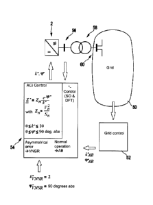
Figure 3 shows grid 15 as the starting point of control according to one
embodiment. Grid
50 acts in particular through measurements onto a very general control, which
is marked
as grid control block 52. In order to adjust an impedance Z- , such general
grid control
may specify values for the adjustment factor k- or, respectively, kA-B and for
the ad-
justment phase angle yo- or, respectively, y0A-B . Here, index AB means normal
operation
of grid 50, i.e. operation without any system incidents. But there may be
certain asymme-
tries.
Figure 3 also suggests that in the case of an asymmetrical disturbance, a
constant value,
such as 2, is set for adjustment factor k- or, respectively, kv-AisR . In such
case, an
absolute value of 900 is specified for adjustment phase angle yo- or,
respectively,
yovNsR= VNSR here means "Voltage Negative Sequence Reactance," whereby for the
negative sequence a reactance is specified in the case of a disturbance. In
such case of
an asymmetrical disturbance in the grid, no variable adjustment phase angle co-
is used;
instead, a pure reactance is applied as a consumer.
Inverter control block 54 controls inverter 2 accordingly. Here, inverter 2
corresponds to
that in Fig. 2a, and reference sign 54 for an inverter control block 54 has
also been used
in Fig. 2a. However, Fig. 2a and Fig. 3 are schematic illustrations and may
differ in terms
of their details.
The controlling of inverter 2 by inverter control block 54, as shown in Fig.
3, comprises
various control processes, and reference is therefore again made to the
control process
explained in Fig. 2c. However, when it comes to illustrating the aspect of how
the imped-
ance is specified, Fig. 3 illustrates only the delivery or rather action of
adjustment factor
k- and adjustment phase angle yo- onto inverter 2. But inverter control is not
limited to
only specifying such values.
CA 02887594 2015-04-07
- 10 -
The dashed arrow also indicates a possible reaction of inverter 2 or of
factors existing at
inverter outlet 56 onto inverter control block 54 and thus onto the inverter
control. Finally,
inverter 2 releases a three-phase, asymmetrical current for injection at its
inverter outlet
56 and injects it into grid 50 at grid connection point 60 via the illustrated
transformer 58.