Note: Descriptions are shown in the official language in which they were submitted.
CA 02887986 2015-04-13
WO 2014/081413
PCT/US2012/066052
- 1 -
CLOSURE HAVING A LINER AND PULL RING
TECHNICAL FIELD
This invention relates to container closures. The invention is more
particularly related
to a closure for use with a container wherein a tearable membrane (e.g.,
thermoplastic coated
foil liner) is interposed between the container and a portion of the closure.
BACKGROUND OF THE INVENTION
AND
TECHNICAL PROBLEMS POSED BY THE PRIOR ART
Various contents, including baby formula, food items, granules, liquids,
creams,
powders, small articles, etc., may be conventionally packaged in a container
having a closure
that can be opened. The container with the closure mounted thereon and the
contents stored
therein may be characterized as a "package."
The inventor of the present invention has discovered a novel structure for a
container
closure, and has also discovered a novel method for making the closure wherein
the closure
includes advantageous features not heretofore taught or contemplated by the
prior art.
SUMMARY OF THE INVENTION
According to the present invention, a closure is provided for a container that
has an
opening to the container interior wherein contents may be stored. A tearable
membrane (e.g.,
"liner") is initially provided as part of the closure so that the membrane can
be located to extend
across at least a portion of the container opening when the closure is mounted
on the container.
The membrane is preferably initially secured by thermal bonding (i.e., heat
sealing or plastic
welding) in, and as part of, the closure, and the membrane is also preferably
subsequently
secured by thermal bonding to a container to provide a hermetic seal initially
over the entire
opening of the container. However, in some applications, a hermetic seal of
the membrane to
the container (by thermal bonding or otherwise) may not be required or
desirable, and the
closure may also be designed to be completely removable from the container.
Depending
upon the application, the closure may also include a lid.
More specifically, according to the broad aspects of one form of the
invention, the
closure includes a closure body for mounting on a container that has an
opening to the
CA 02887986 2015-04-13
WO 2014/081413
PCMJS2012/066052
- 2 -
container interior wherein contents may be stored. The closure body defines an
opening
through the closure body. A membrane is attached to the closure body and
extends across at
least a portion of the closure body opening.
In one preferred form of the invention, the membrane is imperforate and
extends across
the entire closure body opening to initially occlude the closure body opening.
In another form of the invention, the membrane need not extend completely
across the
closure body opening, and, for example, the membrane may define one or more
small orifices
that extend through the membrane and that are initially occluded by an
auxiliary structure that
(1) is attached to one side of the membrane over the small orifice or
orifices, and (2) can be
subsequently opened.
In either form of the invention, a pull ring is provided separately from the
closure body
and is attached to the membrane at the closure body opening. A user can pull
the pull ring to
tear at least a portion of the membrane away from the closure body to provide
either access, or
increased access, through the closure body opening.
The inventive closure permits the user to conveniently and easily open the
membrane.
To this end, the closure pull ring that is attached to the membrane has (a) a
reduced pull force,
and (b) a consistent pull force (i.e., substantially the same pull force from
package to package).
A feature of the invention is that the pull ring is molded separately from the
closure
body and is separately attached to the membrane. The novel closure structure
acconunodates
the molding of the closure body from thermoplastic material while (a) avoiding
the prior art
problem of trying to force the molten plastic through small frangible bridges
to form a pull ring
unitary with the closure body, and (b) avoiding, or at least minimizing, the
creation of molded
plastic knit lines in the pull ring.
If the various components of the closure (e.g., closure body and pull ring
(and optional
utensil, if employed)) are attached to the membrane by adhesive instead of
thermal bonding,
then there is no need to have a metallic layer in the membrane for generating
thermal bonding
heat by an electric field.
In some applications, the membrane need not be hermetically sealed to the top
of the
container (e.g., if air ingress can be tolerated). In such a case, the
membrane, (although either
adhesively sealed or thermally bonded (i.e., heat-sealed), to and across the
inside of, the
overlying closure body), can be merely clamped against the top of the
container by the closure
CA 02887986 2015-04-13
WO 2014/081413
PCT/US2012/066052
=
- 3 -
body using a snap-fit attachment of the closure body to the container.
However, if
removability of the closure, per se, is desirable, then the closure body could
be merely screwed
on to the container or bayonet-mounted to the container.
The molding of the pull ring and the optional utensil each as a separate
component not
unitary with the closure body permits the pull ring and utensil to be
positioned on the
membrane in an optional, overlapping relationship for a compact arrangement.
Such an
overlapping relationship of the pull ring and utensil would not be possible if
the pull ring and
utensil are molded together as a unitary part of the closure body.
Molding the pull ring and optional utensil each separately from the closure
body also
permits the utensil to be attached to the underside of the membrane in an
alternate
embodiment¨something not possible if the pull ring and utensil are molded
together unitary
with the closure body. Attachment of the utensil to the underside of the
membrane can reduce
the overall height of the closure because the utensil will then be located in
the head space over
the product in the container. Such a reduction of closure height may be
desirable in some
applications.
By molding the pull ring separately, and not as a unitary part of the closure
body with
frangible bridge attachments, the magnitude of the pull force required to
remove the pull ring,
and the variability of the required pull force, is much reduced unit-to-unit.
This provides a
better repeatability of the opening process unit-to-unit. This provides a more
consistent
manufactured article unit-to-unit.
Molding the pull ring separately from the closure body eliminates the need for
frangible
bridges, and thus the user does not ever encounter broken stubs of frangible
bridges which are
employed in prior art closures and which might cause scratching or discomfort.
Further, molding the pull ring separately from the closure body to eliminate
the need for
frangible bridges necessarily eliminates the potential problems that can arise
with prior art
closures when molding a pull ring through a small volume of frangible bridges,
and this
eliminates or minimizes the flow knit lines that can occur as a result of the
molten plastic
having to flow through small volume frangible bridges.
Molding the pull ring (and optional utensil) separately permits a different
color
thermoplastic material to be used for the pull ring (and/or utensil) compared
to the closure
body.
CA 02887986 2015-04-13
WO 2014/081413
PCT/US2012/066052
- 4 -
Molding the pull ring (and optional utensil) separately from the closure body
allows the
mold for the closure to be greatly simplified, and that can result in a less
costly mold for the
closure body. The cost reduction can be greater than the added cost required
for a separate
mold for the pull ring (and optional utensil).
The closure inhibits tampering with the package, and provides evidence of
tampering if
the membrane has been breached before the intended first user receives the
package.
The closure does not necessarily require a lid or overcap on the closure body
over the
membrane (e.g., where the closure is part of a "one-time use" package.
The closure can be provided with a design that accommodates efficient, high
quality,
large volume manufacturing techniques with a reduced product reject rate.
In accordance with the present invention, a method of making a closure for a
container
that has an opening comprises the step of providing a closure body for
mounting on the
container, with the closure body defining an opening through the closure body.
The present
method further contemplates providing a membrane, and providing a pull ring
that is separate
from the closure body.
In accordance with the present method, the membrane is attached to the closure
body so
that the membrane extends across at least a portion of the closure body
opening. The present
method further entails attaching the pull ring to the membrane at the closure
body opening,
whereby a user can pull the pull ring to tear a portion of the membrane away
from the closure
body, to thereby provide access or increased access through the closure body
opening.
In one disclosed method for practicing the present invention, the step of
attaching the
membrane to the closure body is performed prior to the step of attaching the
pull ring to the
membrane. In accordance with the illustrated embodiment, the closure includes
the lid having
an internal, resilient spud, with the step of attaching the pull ring to the
membrane including
engaging the spud with the pull ring.
In an alternate method of practice of the present invention, the step of
attaching the pull
ring to the membrane is performed prior to the step of attaching the membrane
to the closure
body. In this aspect of the present invention, the pull ring is attached to a
web from which the
membrane is formed, with the membrane cut from the web with the pull ring
attached to the
membrane. The membrane with the pull ring attached thereto is thereafter
attached to the
closure body so that the membrane extends across at least a portion of the
closure body
81786705
- 5 -
opening.
The closure can optionally be designed to accommodate its use with a variety
of
conventional or special containers having a variety of conventional or special
container
finishes, including conventional threaded, or snap-fit, attachment
configurations. Numerous
other advantages and features of the present invention will become readily
apparent from the
following detailed description of the invention, from, the claims, and from
the accompanying
drawings.
In some embodiments of the present invention, there is provided a closure for
a
container that has an opening to the container interior wherein contents may
be stored, said
.. closure comprising: a closure body for mounting on said container, said
closure body defining
an opening through said closure body; a membrane attached to said closure body
and
extending across at least a portion of said closure body opening; and a pull
ring that is
separate from said closure body and that is attached to said membrane at said
closure body
opening whereby a user can pull said pull ring to tear at least a portion of
said membrane
away from said closure body to provide either access or increased access
through said closure
body opening; said membrane includes at least one metallic layer and said pull
ring is formed
from a thermoplastic material that is thermally bonded to said membrane.
In some embodiments of the present invention, there is provided a method of
making a closure for a container that has an opening to the container interior
wherein contents
.. may be stored, comprising the steps of: providing a closure body for
mounting on said
container, said closure body defining an opening through said closure body;
providing a
membrane; said membrane includes at least one metallic layer; providing a pull
ring that is
separate from said closure body; said pull ring is formed from a thermoplastic
material;
attaching said membrane to said closure body so that said membrane extends
across at least a
portion of said closure body opening; and attaching said pull ring to said
membrane at said
closure body opening, whereby a user can pull said pull ring to tear at least
a portion of said
membrane away from said closure body to provide either access or increased
access through
CA 2887986 2018-10-16
81786705
- 5a -
said closure body opening, wherein said step of attaching said pull ring to
said membrane
includes thermally bonding said pull ring to said membrane.
BRIEF DESCRIPTION OF IRE DRAWINGS
In the accompanying drawings forming part of the specification, in which like
numerals are employed to designate like parts throughout the same,
FIG. 1 is a fragmentary, isometric view of a first embodiment of the closure
of the
present invention in the form of a separate dispensing closure according to a
preferred form of
the invention, and the closure is shown installed on a container with the
closure lid closed;
FIG. 2 is a fragmentary, side elevational view of the components shown in FIG.
1;
FIG. 3 is a top, plan view of the closed closure shown in FIG. 1;
FIG. 4 is a cross-sectional view taken generally along the plane 4-4 in FIG.
3;
FIG. 5 is a greatly enlarged, fragmentary, cross-sectional view of a portion
of the
structure enclosed in the circle designated "FIG. 5" in FIG. 4, and in FIG. 5
the thickness
ofthe membrane is exaggerated for ease of illustration and clarity;
FIG. 6 is an isometric view of the closure with the lid open;
FIG. 7 is an isometric view like FIG. 5, but FIG. 7 shows the closure after
the pull
ring and portion of the foil liner have been torn away to provide access to
the container
interior;
FIG. 8 is an isometric view of the closure alone in the as-molded condition as
viewed from above with the lid open and prior to closing the lid, and prior to
installing the foil
liner and pull ring;
FIG. 9 is an isometric view of the as-molded closure in FIG. 8, but FIG. 9
shows
the closure from the bottom;
CA 2887986 2018-10-16
81786705
- 5b -
FIG. 10 is a fragmentary, isometric view of the pull ring alone in the as-
molded
condition as viewed from above;
FIG. 11 is an isometric view of the as-molded pull ring in FIG. 10, but FIG.
11
shows
CA 2887986 2018-10-16
CA 02887986 2015-04-13
WO 2014/081413
PCT/US2012/066052
- 6 -
the pull ring from the bottom;
FIG. 12 is a somewhat diagrammatic view of one form of a process or method by
which
a plurality of pull rings can be positioned and secured to a web strip or web
of material from
which the closure membrane is defined, and FIG. 12 shows how such individual
membranes
are defined on the web, and how each membrane receives a pull ring attached
thereto, and how
each assembly of the pull ring and membrane is subsequently separated from the
web;
FIG. 13 is an isometric view of the closure as viewed from underneath the
closure prior
to installation of the closure on a container, and FIG. 13 shows a portion of
the membrane
broken away to illustrate details of the closure above the membrane, and FIG.
13 also shows
the closure with the lid closed in a configuration that the closure would have
prior to
installation on a container;
FIG. 14 is an isometric view from above of an alternate embodiment of the
closure
shown in the as-molded condition with the lid open, and in this alternate
embodiment the
closure includes a utensil in the form of a food item spear which is attached
to the upper surface
of the membrane beneath the finger pull loop of the pull ring;
FIG. 15 shows yet another embodiment of the closure, and FIG. 15 is an
isometric view
of the underside of the closure with the lid open and with a portion of the
membrane broken
away to better illustrated interior detail, and FIG. 15 shows the attachment
of a utensil in the
form of a food item spear attached to the bottom surface of the membrane;
FIG. 16 is an isometric view, as viewed from above, of yet another embodiment
of the
closure, and in FIG. 16 the closure is shown with the lid in the open
condition;
FIG. 17 is a view similar to FIG. 16, but FIG. 17 shows the closure after
removal of a
removable small dispensing orifice cover disc;
FIG. 17A is an isometric view similar to FIG 16, but FIG. 17A shows yet
another
embodiment of the closure, and in FIG. 17A the closure is shown with the lid
in the open
condition;
FIG. 17B is a view similar to FIG. 17A, but FIG. 1711 shows the closure after
removal
of a removable small dispensing orifice cover disc;
FIG. 17C is a plan view of the closure shown in FIG. 17A prior to removal of
the small
dispensing orifice cover disc;
FIG. 17D is a cross-sectional view taken generally along the plane 17D-17D in
FIG.
CA 02887986 2015-04-13
WO 2014/081413
PCT/US2012/066052
- 7 -
17C;
FIG. 17E is a greatly enlarged, fragmentary, cross-sectional view of a portion
of the
structure enclosed in the circle designated "FIG. 17E" in FIG. 17D, and in
FIG. 17E the
thickness of the membrane is exaggerated for ease of illustration and clarity;
FIG. 18 is an exploded, isometric, diagrammatic view showing a low volume
production process for assembling the first embodiment of the closure of the
present invention
illustrated in FIGS. 1-13;
FIG. 19 is a view similar to FIG. 18, but in FIG. 19 the membrane is shown
placed on
the nest of a first thermal bonding machine;
FIG. 20 is a view similar to FIGS. 18 and 19, but in FIG. 20, the closure has
been
lowered onto the membrane on the nest of the first thermal bonding machine;
FIG. 21 is a view similar to FIGS. 18-20, but FIG. 21 shows the pressure pad
of the
thermal bonding machine lowered against the closure on the nest of the thermal
bonding
machine;
FIG. 22 is a diagrammatic plan view of the first thermal bonding machine and
closure
components shown in FIG. 21;
FIG. 23 is a diagrammatic, cross-sectional view taken generally along the
plane 23-23
in FIG. 22;
FIG. 24 is a greatly enlarged, fragmentary, cross-sectional view of a portion
of the
structure enclosed in the circle designated "FIG. 24" in FIG. 23, and in FIG.
24 the thickness of
the membrane is exaggerated for ease of illustration and clarity, and in FIG.
24 the closure
components and the first thermal bonding machine are shown wherein the closure
lid interior
spud is pressed against the top surface of a portion of the pull ring (causing
deformation or
flexing of the spud) so as to insure good contact between the bottom surface
of the pull ring and
the top surface of the membrane during the induction heating step of the
process;
FIG. 25 is an exploded isometric view of a partially completed first
embodiment of the
closure positioned in relation to a second thermal bonding machine;
FIG. 26 is a view similar to FIG. 25, but in FIG. 26 the closure with the
thermally
bonded membrane has been placed on top of the open nest of the second thermal
bonding
machine with a non-stick or non-thermal bonding absorptive tape barrier (not
visible) located
on the underside of the closure membrane over the nest of the second thermal
bonding
CA 02887986 2015-04-13
WO 2014/081413
PCT/US2012/066052
- 8 -
machine;
FIG. 27 is a view similar to FIG. 26, but in FIG. 27, the pull ring has been
positioned on
top of the upwardly facing surface of the closure membrane within the closure
body;
FIG. 28 is a view similar to FIG. 27, but FIG. 28 illustrates a further step
in the process
wherein the closure lid has been closed;
FIG. 29 is a view similar to FIG. 28, but FIG. 29 shows a further step in the
process
wherein the pressure pad of the second thermal bonding machine has been
lowered against the
closed closure, and wherein the induction heating system has been energized or
excited to
create or fuse of the thermoplastic material at the innerface of the membrane
and pull ring;
FIG. 30 is a diagrammatic, plan view of the components and machine in FIG. 29;
FIG. 31 is a cross-sectional view taken generally along the plane 31-31 in
FIG. 30;
FIG. 32 is a greatly enlarged, fragmentary, cross-sectional view of a portion
of the
structure enclosed in the circle designated "FIG. 32" in FIG. 31, and in FIG.
32 the thickness of
the membrane and non-thermal bondable absorptive tape is exaggerated for ease
of illustration
and clarity, and in FIG. 32 the closure components and the second thermal
bonding machine
are shown wherein the closure lid interior spud is pressed against the top
surface of a portion of
the pull ring (causing deformation or flexing of the spud) so as to insure
good contact between
the bottom surface of the pull ring and the top surface of the membrane during
the induction
heating step of the process; and
FIG. 33 is an exploded, isometric, diagrammatic view showing a step in a high-
volume
process for assembling the embodiment of the closure illustrated in FIGS. 16
and 17;
FIG. 34 is a view similar to FIG. 33, but in FIG. 34 the pull ring is placed
on the web of
membrane material on a thermal bonding machine;
FIG. 35 is a view similar to FIG. 34, but in FIG. 35 the web of membrane
material with
the pull ring welded thereto is advanced to a next location on the thermal
bonding machine;
FIG. 36 is a view similar to FIG. 35, but in FIG. 36 the small orifice
structure has been
placed and thermally bonded to the web of membrane material;
FIG 37 is a view similar to FIG. 36, but in FIG. 37 the web of membrane
material with
the pull ring and small dispensing orifice structure welded thereto has been
advanced to another
position;
FIG. 38 is a view similar to FIG. 37, but in FIG. 38 the circular disc
membrane has been
CA 02887986 2015-04-13
WO 2014/081413
PCT/US2012/066052
- 9 -
punched from the web of membrane material with the small dispensing orifice
structure and
pull ring welded thereto, and the circular disc membrane has been elevated
with the small
dispensing orifice structure and pull ring mounted thereon;
FIG. 39 is a view similar to FIG. 38, but in FIG. 39 the closure body with the
closed lid
has been lowered onto the nest of the first thermal bonding machine over the
circular disc
membrane to which is attached the small dispensing orifice structure and pull
ring;
FIG. 40 is a view similar to FIG. 39, but in FIG. 40 the thermal bonding
machine weld
head is closed to thermally bond the circular membrane to the inside of the
closure body; and
FIG. 41 is an isometric view of another altemate embodiment of a closure of
the present
invention.
DESCRIPTION OF THE PREFERRED EMBODIMENTS
While this invention is susceptible of embodiment in many different forms,
this
specification and the accompanying drawings disclose only some specific forms
as examples
of the invention. The invention is not intended to be limited to the
embodiments so described,
however. The scope of the invention is pointed out in the appended claims.
For ease of description, many of the figures illustrating the invention show
the
embodiments of the closure as including a separate, closure in the typical
orientations that the
closure would have at the top of a container when the container is stored
upright on its base, and
terms such as upper, lower, horizontal, etc., are used with reference to this
position. It will be
understood, however, that the closure of this invention may be manufactured,
stored,
transported, used, and sold in an orientation other than the orientations
described.
The closure of this invention is suitable for use with a variety of
conventional or special
containers, the details of which, although not fully illustrated or described,
would be apparent
to those having skill in the art and an understanding of such containers. The
particular
container, per se, that is illustrated and described herein forms no part of,
and therefore is not
intended to limit, the present invention, It will also be understood by those
of ordinary skill that
novel and non-obvious inventive aspects are embodied in the described
exemplary closure
alone.
A first embodiment of a closure of the present invention is illustrated in
FIG. 13 and is
designated generally therein by reference number 20 in FIG. 1. In the first
embodiment
CA 02887986 2015-04-13
WO 2014/081413
PCT/US2012/066052
- 10 -
illustrated, the closure 20 is provided in the form of a separate closure 20
which is adapted to be
mounted or installed on a container 22 that would typically contain contents
such as a product
or products consisting of articles or fluent material. The container 22
includes a portion
extending upwardly to define an opening 24 (FIG. 4) to thc container interior.
The first
embodiment of the closure 20 is particularly suitable for use with a container
22 that is formed
from polyethylene.
A membrane 26 in the form of a tamper-evident foil liner 26 is disposed within
the
closure 20 to be located across the top of the container over the opening 24.
Hereinafter the
terms "membrane" and "liner" will be used interchangeably. FIG. 6 shows the
liner 26 before
part of it has been tom away, and FIG. 7 shows the opened closure 20 after a
user has torn away
a part of the liner coextensive with an access orifice or opening defined in
the closure 20 by a
surrounding orifice wall 25.
The membrane 26 may be of any special or conventional type. In the preferred
embodiment illustrated in FIG. 5, the membrane 26 is a commercially available
foil liner sold
under the trade designation "LAMINATE 150MDPE/0.001/100CPP" by Coflex
Packaging
having an office at 1970 John-Yule Street, Chambly, Quebec, J3L 6W3, Canada
(Website:
www.deluxepaper corn). This liner 26 consists of a layer of 25 micron thick
aluminum foil
27 bonded with adhesive to a top layer of 25 micron thick cast polypropylene
29 and bonded
with adhesive to a bottom layer of 38 micron thick medium density polyethylene
28. The liner
26 has a total thickness of about 94 microns and has a total basis weight of
about 132 grams per
square meter. The particular composition and structural details of the liner
26 form no part of
the broad aspects of the present invention.
In one preferred embodiment form of a package employing the closure of the
present
invention illustrated in FIGS. 1-13, the liner 26 is initially attached to the
closure 20 to portions
of the downwardly facing, interior surface or surfaces of the closure 20. The
liner 26 is also
preferably subsequently attached to the top of the container 22. The
particular type of liner 26
described above can be readily attached to the closure 20 by thermally bonding
(i.e., heat
sealing) the polypropylene top surface to the closure 20 if the closure 20 is
molded from
polypropylene, and later the bottom polyethylene surface of the liner 26 can
be readily
thermally bonded to a polyethylene container 22.
The illustrated first embodiment of the closure 20 is adapted to be used with
a container
CA 02887986 2015-04-13
WO 2014/081413
PCT/US2012/066052
- -
22 having an opening 24 to provide access to the container interior and to a
product contained
therein (after a portion of the liner 26 is tom away). The closure 20 can be
used on containers
holding various substances, including, but not limited to, baby formula,
powders, liquids,
suspensions, mixtures, pieces of solid food, discrete articles, etc. The
container 22 may have a
flexible wall or walls (or a rigid wall or walls) which can be grasped by the
user.
The container 22 may have any suitable configuration, The container 22, per
se, does
not form a part of the broadest aspects of the present invention, per se. The
closure 20 is a
completely separate article or unit (e.g., a closure 20) which can comprise
multiple pieces, and
which is adapted to be removably, or non-removably, installed on a previously
manufactured
container 22 that has an opening 24 to the container interior.
It is presently contemplated that many applications employing the closure 20
will
conveniently be realized by molding a main portion of the closure 20 from
suitable
thermoplastic material as a unitary structure. However, not all of the
portions of the closure
are molded together as a unitary structure, In the illustrated first
embodiment, at least some of
the portions of the closure are molded from a suitable thermoplastic material,
such as, but not
limited to, polypropylene. The closure portions which are separately molded
may be molded
from different materials. The materials may have the same or different colors
and textures.
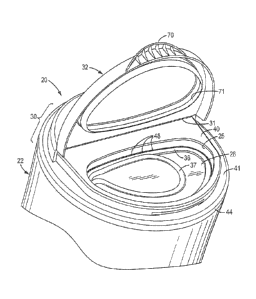
As can be seen in FIG. 6, the first embodiment of the closure 20 includes a
number of
basic components, (1) a unitary molded body 30 and lid 32 connected together
with an attached
hinge 31, (2) a membrane 26 (such as a foil liner) attached to the closure
body 30 (e.g., by
thermal bonding or adhesive), and (3) a pull ring 36 attached to the membrane
26 (e.g., by
thermal bonding or adhesive). The pull ring 36 includes an offset (elevated)
finger pull loop
37.
In some applications, the lid 32 may be omitted altogether. In the preferred
form of the
first embodiment of the invention, the lid 32 is provided to be closed over,
and cover, a portion
of the closure body 30. The lid 32 can be moved to expose the upper part of
the body 30 (FIG.
6). The lid 32 is movable between (1) a closed position over the body 30 (as
shown in FIG. 1),
and (2) an open position (as show in FIG. 6). In the illustrated first
embodiment, the lid 32 is
hinged to the body 30 so as to accommodate pivoting movement of the lid 32
between the
closed position and open position. In an alternative design (not illustrated),
the lid 32 may be
a separate component which is completely removable from the closure body 30,
or the lid 32
CA 02887986 2015-04-13
WO 2014/081413
PCT/US2012/066052
- 12 -
may be tethered to the body with a strap. In another alternative design (not
illustrated), the lid
could be omitted altogether.
In a presently preferred form of the first embodiment of the closure 20, the
unitary
closure body 30 and lid 32 are molded from polypropylene sold under the
designation 3727W
by Total Petrochemical USA, Inc., 120 Louisiana Street, Suite 1800, Houston TX
77002,
U.S.A.
As can be seen in FIG. 6, the closure body 30 includes a raised deck 40,
peripheral
shoulder 41, and a skirt 44. The skirt 44 extends downwardly from the
periphery of the deck
40 (as shown in FIG. 5) to surround the liner 26. As can be seen in FIG. 5,
the orifice wall 25
extends downwardly from the deck 40 to define the closure body access opening.
The lower edge of the orifice wall 25 defines a plurality of downwardly
pointing
pyramid shaped teeth 48 (FIGS. 5-9 and 13) which are spaced apart around the
opening defined
by the orifice wall 25.
As can be seen in FIG. 5, the interior of the closure 20 can be secured to the
top of the
container, preferably by thermal bonding of the liner 26 to the top of the
container 22.
Alternatively, or in addition, the container 22 and closure 20 could be
provided with
another connecting means, such as a snap-fit bead or groove arrangement (not
illustrated).
Also, the closure body 20 could instead be attached to the container 22 by
means of a bayonet
mount or threaded attachment.
The closure body 30 may have any suitable configuration for receiving or
otherwise
accommodating an upwardly projecting portion of the container 22 or for
accommodating any
other portion of a container received within the particular configuration of
the closure body
30--even if a container does not have a reduced size upper open end. The main
part of the
container 22 may have a different cross-sectional shape than the upper portion
of the container
that defines the container opening.
In the illustrated first embodiment, where a lid 32 is provided and where the
lid 32 is
connected to the closure body 30 with a hinge 31, the hinge 31 may be of any
suitable type.
One form of a hinge 31 that may advantageously be used is a conventional
reduced-thickness
living hinge as illustrated. Other types of hinges could be used. In some
applications, the
hinge could be omitted altogether, and the lid 32 need not be connected as a
unitary part of the
body 30. In other applications, it may be desirable to omit the lid 32
entirely.
CA 02887986 2015-04-13
WO 2014/081413
PCT/US2012/066052
- 13 -
Where a lid, such as the lid 32, is employed as shown in FIG. 5, it may be
desirable to
provide a conventional latch bead 60 along a portion or portions of the lower
edge of the lid 32,
and to provide a cooperating conventional latch groove 62 around a portion or
portions of the
closure body 30 below the deck 40 and above the shoulder 41. When the lid 32
is closed, the
lid latch bead 60 overrides the edge of the body deck 40 and establishes a
latched engagement
in the body latch groove 62. To facilitate opening of the lid 32, the lid 32
includes a finger or
thumb lift 68 (FIGS. 1-8).
The lid 32 includes an internal, resilient spud 71 (FIGS. 4-9). In the first
embodiment
of the closure 20 is illustrated in FIGS. 1-13. The spud 70 seals against the
inside surface of
the orifice wall 25 when the lid 32 is closed. As shown in FIG. 5, the lower
edge of the spud
71 initially also contacts the upper surface of the periphery of the pull ring
36 when the lid 32 is
closed.
In some applications, the teeth 48 could be omitted, but the teeth 48 are
preferred in
many applications. Also, the liner 26 need not be thermally bonded or
otherwise attached to
the downwardly facing surface of the closure body 30 at the pointed ends of
the teeth 48.
Rather, in some applications, the liner 26 could be attached to the downwardly
facing surface
of the closure body 30 at locations spaced some distance laterally outwardly
from the orifice
wall 25 and teeth 48. However, in the preferred embodiment of the closure 20
shown in FIGS.
1-13, the liner 26 is bonded to the underside of the closure body 30 to
provide a hermetic seal
that is continuous around the periphery of the closure body opening at or
adjacent the teeth 48.
The pull ring 36 is preferably attached to the liner 26 over a substantial
portion of a path
around the interior of the orifice wall 25 and teeth 48. In the first
embodiment illustrated in
FIGS. 1-13, the pull ring 36 defines a continuous path or loop in contact
with, and attached to,
the liner 26. As shown in FIGS. 5 and 11, the underside (i.e., bottom surface)
of the pull ring
36 defines a downwardly projecting rib 52 which contacts only a small portion
of the upwardly
facing surface of the membrane 26. In the first embodiment of the closure 20
illustrated in
FIGS. 1-13, the pull ring 36 is attached to the membrane 26 along the rib 52.
In the preferred
embodiment, the pull ring 36 is thermally bonded to the membrane 26, and the
rib 52 functions
as a "weld concentrator" for facilitating the thermal bonding of the pull ring
36 to the
membrane 26.
FIG. 12 illustrates one way in which the pull ring 36 is oriented on a
membrane 26 on a
CA 02887986 2015-04-13
WO 2014/081413
PCT/US2012/066052
- 14 -
strip or web of membrane material 26. Each membrane 26 has a circular
configuration which
can be stamped or cut from the web material 26' after a pull ring 36 has been
molded and
adhered to the upper surface of the membrane material 26' in the appropriate
orientation.
Alternatively, each membrane 26 can be first cut or stamped from a strip or
web of the
membrane material 26', and a pull ring 36 can be subsequently attached to the
top surface of the
membrane 26. In preferred methods of making the closure 20, the pull ring 36
and membrane
26 are thermally bonded together, and the membrane 26 is thermally bonded to
the closure
body 30¨the particular method steps for such a thermal bonding process, and
variations of
such steps, being discussed hereinafter in detail following descriptions of
alternate
embodiments of the closure 20.
When the closure 20 is initially completed by the manufacturer with the lid 32
in closed
condition as shown in FIG. 13, the closure 20 can be provided to a packager,
and the packager
can install the closure on the container 22 as shown in FIGS. 1-5.
Subsequently, a user who acquires the package can initially open the package
by
opening the lid 32 (to the configuration illustrated in FIG. 6) so as to
provide access to the pull
ring 36. The user can then lift up and pull on the finger pull loop 37 to
exert a force on the pull
ring 36 and on the attached portion of the membrane 26. When the user applies
a sufficient
force to the pull ring 36, the membrane 26 is torn around the inside periphery
of the closure
body opening at the lower edge of the wall 25. If the closure 20 includes
teeth 48 as in the first
embodiment illustrated in FIGS. 1-13, then such teeth 48 assist in the tearing
of the membrane
26. The torn away portion of the membrane 26 and the attached pull ring
36 can then be
discarded, and the user can remove some or all of the contents from the
container 22 through
the opening that has been created.
A preferred method or methods of making the first embodiment of the closure 20
illustrated in FIGS. 1-13 are discussed hereinafter following a description of
some alternate
embodiments of the closure.
FIG. 14 illustrates an alternate form or embodiment of the closure, and in
FIG. 14, the
alternate closure is designated generally by the reference number 120. The
closure 120
includes a closure body 130 and a hinged lid 132. The closure 120 also
includes a membrane
126 to which is attached a pull ring 136 having a finger pull loop 137. The
closure body 130,
lid 132, pull ring 136, and membrane 126 are identical, or substantially
identical, to the
CA 02887986 2015-04-13
WO 2014/081413
PCT/US2012/066052
- 15 -
analogous components of the first embodiment of the closure 20 described above
in detail with
reference to FIGS. 1-13.
Also attached to the membrane 126 is a utensil in the form of a food item
spear 160.
The spear 160 is molded separately from closure body 130, lid 132, and pull
ring 136.
Typically, the spear 160 would be molded from the same thermoplastic material
as the pull ring
136. The spear 160 has a pointed or barbed spear tip 162 and a handle portion
164. The spear
tip 162 and part of the handle portion 164 extend under, and are overlapped
by, the finger pull
loop 137. The handle portion 164 of the spear 160 includes an outwardly
extending
attachment portion 166 which is attached to the membrane 126. In a preferred
form of the
alternate embodiment of the closure illustrated in FIG. 14, the attachment
portion 166 of the
spear 160 is thermally bonded to the top surface of the membrane 126.
FIG. 15 illustrates yet another embodiment of the closure, and this embodiment
is
designated generally by the reference number 220 in FIG. 15. The closure 220
includes a
closure body 230, a lid 232, a membrane 226 (partially broken away in FIG.
15), and a pull ring
236 that includes a finger pull loop 237. These elements are identical, or
substantially
identical, to the analogous elements of the first embodiment of the closure 20
described above
in detail with reference to FIGS. 1-13.
The alternate embodiment of the closure 220 illustrated in FIG. 15 also
includes a
utensil, in the form of a food item spear 260, but the spear 260 is attached
to the bottom surface
of the membrane 226. As with the embodiment of the closure 120 shown in FIG.
14 and
described above, the spear 260 in the embodiment shown in FIG. 15 includes a
point or barbed
spear tip 262, a handle portion 264, and an attachment portion 266. In the
preferred form of
the closure 220, the spear 260 is attached to the underside of the membrane
226 by thermally
bonding the attachment portion 266 to the membrane 226.
FIGS. 16 and 17 show yet another embodiment of the closure of the present
invention,
and in FIGS. 16 and 17 the closure is designated generally by the reference
number 320. The
closure 320, including a closure body 330, has a configuration which is
identical, or
substantially identical, to that of the first embodiment of the closure 20
described above with
reference to FIGS. 1-13. The closure 320 differs only in that a small
dispensing orifice
structure 372 is provided on the membrane 326 within the pull ring 336. The
small dispensing
orifice structure 372 includes an annular base 373 mounted on, and attached
to, the membrane
CA 02887986 2015-04-13
WO 2014/081413
PCT/US2012/066052
-16-
326 (by thermal bonding, or otherwise) and an upwardly extending annular wall
374. The
structure 372 also includes a pull tab 376 and a removable cover disc 378, the
underside of
which is thermally bonded to the membrane 326.
As explained in detail hereinafter, the small dispensing orifice structure 372
can be
opened first and used to drain off some liquid contents of a package prior to
pulling off the
main pull ring 336 to completely open the closure 320. For example, if the
package contains
fruit pieces in a liquid, then the user might want to pour off the liquid
first through a smaller
orifice defined by the small dispensing orifice structure 372 before pulling
off the main pull
ring 336 and creating the larger access opening to the container. However, the
user would not
be required to open the small orifice dispensing structure 372 at all. The
user could instead
initially only pull out the main pull ring 336 along with the attached portion
of the membrane
326 to which is mounted the structure 372 (and that action would cause the
closure body
opening to be exposed upon tearing away the occluding portion of the membrane
326), and that
would initially provide only a large access opening.
As can be seen in FIG. 17, the disc 378 is disposed at one end of the tab 376
in the
annular base 373. The disc 378 includes a plurality of frangible bridges 380
which are initially
molded unitary with the base 373 and which can be broken when sufficient force
is exerted on
the tab 376 by the user.
The underside of the disc 378 is attached (e.g., by theunal bonding or
otherwise) to the
top surface of the membrane 326. Teeth 379 (FIG. 17) are preferably provided
on the
downwardly facing bottom surface of the dispensing orifice structure base 373
just radially
beyond the peripheral edge of the disc 378 to facilitate tearing away of a
small circular portion
of a membrane 326 from inside the dispensing orifice structure 372 to create a
small dispensing
orifice 381 (FIG. 17). In this form of the closure 320 illustrated in FIGS. 16
and 17, the
structure 372 is separately molded apart from the large pull ring 336. In
another form of the
closure 320 (not illustrated), an outer edge of the base 373 is connected to
the inner edge of the
large pull ring 336 so that the entire small dispensing orifice structure 372
can be molded
unitary with the pull ring 336.
After the user has finished dispensing the desired amount of contents through
the small
dispensing orifice, the user may then pull the large pull ring 336 to tear
away the rest of the
membrane 326 from the closure body opening to provide increased access through
the closure
CA 02887986 2015-04-13
WO 2014/081413
PCT/US2012/066052
- 17 -
body (as with a scoop or spoon, or by pouring).
FIGS. 17A, 17B, 17C, 17D, and 17E illustrate yet another embodiment of the
closure of
the present invention, and in FIGS. 17A-17D the closure is designated
generally by the
reference number 320A. The closure 320A has a configuration which is identical
to that of the
embodiment of the closure 320 described above with reference to FIGS. 16 and
17 except that
the closure 320A has a somewhat different small dispensing orifice structure
372A (FIG. 17A)
which is next described in detail. The small dispensing orifice structure 372A
includes an
annular base 373A mounted on, and attached to, the membrane 326A (by thermal
bonding, or
otherwise), and the structure 372A further includes an annular wall 374A
extending upwardly
from the base 373A.
The structure 372A also includes a pull tab 376A extending from a circular,
removable
cover disc 378A. As can be seen in FIG. 17E, the periphery of the disc 378A is
attached at the
bottom of the annular wall 374A to a generally cylindrical surrounding portion
of the structure
372A by a frangible, reduced-thickness portion of material 380A. The disc 378A
is spaced
above the membrane 326A. When the user exerts sufficient force on the tab
376A, the disc
' 378A can be broken away (as illustrated in FIG. 17B).
hi the initial condition as provided to the user, the removable cover disc
378A is located
over a portion of the membrane 326A, and the portion of the membrane 326A that
underlies the
removable cover disc 378A defines a plurality of small dispensing orifices,
apertures, or
openings 381A. The small dispensing orifices 381A are, of course, not exposed
until the user
opens the lid and pulls the tab 376A to tear away the disc 378A. Such a small
dispensing
orifice structure 372A might be useful for initially sprinkling the product
(e.g., salt, pepper,
sugar, etc.) prior to opening the main, larger opening of the closure to
provide increased access
for removing larger amounts or bulk amounts of the product (as with a scoop or
spoon, or by
pouring).
In the embodiment shown in FIGS. 17A-17E, wherein the membrane defines the
pre-formed small dispensing orifices or openings 381A, the membrane 378A may
be
characterized as extending across at least a portion of the closure body
opening.
FIG. 41 illustrates yet another embodiment of the closure of the present
invention, and
in FIG. 41 the closure is designated generally by the reference number 420.
The closure 420
includes a closure body 430 and a lid 432 that present a different exterior
aesthetic design
CA 02887986 2015-04-13
WO 2014/081413
PCT/US2012/066052
- 18 -
configuration than does the previously described first embodiment of the
closure 20 described
above with reference to FIGS. 1-13. The body 430 and lid 432 each has a
generally oval
configuration instead of the circular configuration employed in the first
embodiment of the
closure 20. Also, in the alternate embodiment of the closure 420 illustrated
in FIG. 41, the lid
432 is hinged at the rear of the lid (the hinge not being visible in FIG. 41).
The closure 420
also differs from the closure 20 in that the front of the lid 432 of the
closure 420 does not
include an outwardly projecting thumb lift like the thumb lift 70 of the
closure 20 (FIG. 1), and
the closure body 430 instead includes an inwardly concave finger recess 431.
Despite the
differences with respect to (1) the shape of the closure 420, (2) the location
of the lid hinge, and
(3) the use of thumb recess 431 instead of a projecting thumb lift on the lid,
the functional
features of the internal structures (not visible in FIG. 41) of the closure
420 are functionally
analogous to the internal functional features of the closure 20 described
above in detail with
reference to FIGS. 1-13, and the closure 420 employs internal components and
elements
analogous to the internal components and elements, respectively, of the
closure 20 described
above in detail with reference to FIGS. 1-13.
The present invention is further directed to a method of making a closure
embodying
the principles of the present invention, wherein the closure includes a
closure body for
mounting on an associated container, with a tearable membrane attached to the
closure body,
and a pull ring, separate from the closure body, in turn, attached to the
membrane. As will be
further described, in one aspect of the present invention, it is contemplated
that the method of
making the present closure is effected by attaching the membrane to the
closure body prior to
attaching the pull ring to the membrane. In an alternative method of making
the present
closure, the pull ring is attached to the membrane, such as by attachment to a
membrane-making web, with subsequent cutting of the membrane from the web, for
attachment of the membrane and pull ring to the associated closure body.
With reference to FIGS. 18-32, the first method of making a closure embodying
the
principles of the present invention will now be described. As will be further
described, FIGS.
18-24 illustrate attachment of a membrane 26 to a closure body 30, configured
in accordance
with the previously described embodiment illustrated in FIGS. 1-11 and 13.
FIGS. 25-32
illustrate attachment of a pull ring 36 to membrane 26 previously attached to
the closure body
30.
CA 02887986 2015-04-13
WO 2014/081413
PCT/US2012/066052
- 19 -
With particular reference to the exploded, isometric, diagrammatic view of
FIG. 18,
therein is illustrated an induction welder 500 for effecting thermal bonding
and attachment of
membrane 26 to closure body 30. The induction welder 500 includes a nest 502
for receiving
the membrane 26, with the nest 502 configured to position the membrane 26 in
contact with the
underside of closure body 30 when the closure body 301s positioned on the nest
502, on top of
the membrane 26.
The induction welder 500 includes an induction coil 504, with an associated
pressure
pad 506 moveable relative to the induction welder nest 502 for applying
pressure to the closure
body 30 during the induction welding process.
An exemplary induction welder for practice of the present invention is an
Ambrell Easy
Heat, Bapco Number WS2/4 and Number WS1/1, supplied by Ameritherm Induction
Heating
=
Limited, Saxon Way, Cheltenham, Gloucestershire, UK GL52 6RU.
With particular reference to FIG. 19, the present method is initiated by
positioning
membrane 26 on nest 502 of the induction welder 500 with the nest 502 having a
shape which
corresponds to, but is slightly smaller than, the membrane 26. Thereafter, as
illustrated in
FIG. 20, the closure body 30, with the lid 32 closed, is placed on the nest
502 of the induction
welder 500, such that the membrane 26 is positioned against the underside of
closure body 30.
Pressure pad 506 is next moved relative to the induction welder 500 as
illustrated in
FIGS. 21-24, whereby pressure is applied to the closed lid 32 which transfers
force to the
closure body 30, urging the closure body 30 into intimate contact with the
membrane 26
positioned therebeneath. Induction welding is initiated by activation of
induction coil 504,
whereby the membrane 26 thermally bonded and is attached to the closure body
30 in sealing
relationship.
hi accordance with the presently preferred practice of the present invention,
pressure
applied to the closure lid 32 and body 30 by pressure pad 506 can be provided
at between about
60 to 90 pounds. Induction current of 135-165 amperes is provided to the
induction coil 504,
with an induction time of the order of 0.910 1.5 seconds. This is followed by
a cooling time of
1.0 seconds, with the resultant temperature of the laminate structure of the
membrane 30
reaching between about 230 to 270 F.
By induction welding of the membrane 2610 closure body 30, the membrane is
attached
to the closure body 30 so that the membrane 26 extends across at least a
portion of the closure
CA 02887986 2015-04-13
WO 2014/081413
PCT/US2012/066052
- 20 -
body opening (the opening being defined by the wall 25 as can be seen in FIG.
6). As
illustrated in FIG. 24, the periphery of the membrane 26 is sealingly attached
to the underside
of the closure body 30, with the membrane 26 positioned for engagement and
piercing by the
teeth 48 of the closure body.
After the membrane 26 has been attached to the closure body 30, the assembled
closure
body and membrane are removed from the induction welder 500 for subsequent
attachment of
pull ring 36 to the membrane 26.
With particular reference to FIGS. 25-32, attachment and thermal bonding of
the pull
ring 36 to membrane 26 is effected by an induction welder 510 having a nest
512 upon which
the assembled closure body and membrane are positionable. The induction welder
510
includes an induction coil 514, with an associated pressure pad 516 positioned
in operative
association with the induction welder nest 512 in order to apply pressure to
pull ring 36 for
attachment to membrane 26.
For practice of this aspect of the present invention, induction welder 510 may
comprise
a model MIT2 Induction Welder (Serial No. 4128), supplied by Relco UK Ltd.,
Imperial Way,
Watford, England WD24 4JP.
For practice of this aspect of the present invention, an absorptive tape 518,
having
suitably non-adherent surfaces, is positioned on nest 512 of the induction
welder 510. As
shown in FIG. 26, the closure body 30 is next positioned on top of absorptive
tape 518, with a
lid 32 of the closure in the open configuration to expose, and provide access
to, the upper
surface of membrane 26.
As shown in FIG. 27, the pull ring 36 is next positioned on top of the
membrane 26
within the opening defined by closure body 30. Thereafter, as shown in FIG.
28, the lid 32 of
the closure 20 is closed, thus urging resilient spud 71 into engagement with
the pull ring 36
positioned generally within the closure body 30 (see FIG. 32). The pressure
pad 516 is then
moved relative to the induction welder nest 512 and closure 20 to force the
lid 32 against the
closure body 30. Then, the induction coil 514 activated to inductively heat
the laminate of the
membrane 26 to create a thermal bond between the membrane 26 and the pull ring
36. As will
be appreciated, the spud 71 of lid 32 has been particularly configured to
provide the desired
interference with the pull ring 36. The force of the pad 516 on the lid 32
deforms and deflects
the spud 71 so that the spud 71 transfers pressure to the pull ring 36. As
previously described,
CA 02887986 2015-04-13
WO 2014/081413
PCT/US2012/066052
=
- 21 -
the pull ring 36 preferably defines a rib 52 (FIG. 32) which functions as a
"weld concentrator"
for facilitating thermal bonding of the pull ring 36 to the membrane 26.
For practice of this aspect of the present invention, pressure pad 516 is
configured to
exert pressure between about 60 to 180 pounds on the closure lid 32 and body
30. An
induction current of 135 to 165 amperes can be supplied to the induction coil
514, with an
induction time 0.9 to 1.5 seconds, followed by a cooling time of 1.0 seconds.
It is
contemplated that as a result of induction welding in this manner, the
laminate of the
membrane 26 will reach a temperature of between about 230 to 270 F.
While engagement of spud 71 with pull ring 36 is illustrated, contact between
pull ring
36 and membrane 26 can be effected in other ways, such as by leaving lid 32 of
the closure
open, and using a pressure pad shaped to fit inside the closure body opening
for directly
contacting the pull ring.
After the assembled closure 20 has cooled sufficiently, the pressure pad 516
can be
moved relative to the induction welder 510 to permit the assembled closure 20
to be removed
from the induction welder. The absorptive tape 518 is separated from the lower
surface of the
membrane 26 to complete the manufacture of the closure 20 with the separately
molded pull
ring 36 now attached to the membrane 26.
With reference now to FIGS. 33-40, therein is diagrammatically illustrated an
alternative method for making a closure embodying the principles of the
present invention,
including a tearable membrane and pull ring separate from the body of the
closure. In
accordance with this aspect of the present invention, it is contemplated that
higher rates of
production can be achieved by attachment of the pull ring to the tearable
membrane, prior to
attachment of the membrane to the associated closure body. It is further
contemplated that
this can be achieved by attaching the pull ring to a web from which the
membrane can be cut,
then cutting the membrane, and thereafter attaching the membrane along with
the pull ring to
the associated closure body.
With particular reference to FIG. 33, therein is illustrated an exploded,
isometric,
diagrammatic view showing an arrangement for a high-volume process for making
closures
embodying the principles of the present invention. While it will be understood
that practice of
this aspect of the method of the present invention can be employed for making
any of the
previously-described embodiments of the present closure, this aspect of the
method of the
CA 02887986 2015-04-13
WO 2014/081413
PCT/US2012/066052
-22 -
present invention will be described in association with the previously
described closure 320
which is illustrated in FIGS. 16 and 17, and which includes a small dispensing
orifice structure
372 provided on membrane 326 within the associated pull ring 336.
As illustrated in FIG. 33, practice of this aspect of the invention can be
effected by use
of an induction welding apparatus 600, which defines a generally elongated
membrane guide
region 602 along with a membrane web 26 can be positioned and moved for
manufacture of
the closure 320. The welding apparatus 600 includes an induction coil 604 and
membrane die
cutter 608, and a cooperating, vertically moveable membrane punch. Welding
apparatus 600
is configured to effect thermal bonding of the pull ring 336 to the membrane
web 26' from
which the membrane 326 is cut and formed.
As illustrated in FIG. 33, an induction welder 610, having induction coil 614
is further
provided for making the closure 320. Induction welder 610 is operable to bond
the membrane
326 (cut from membrane web 26'), together with the pull ring 336 and the
dispensing orifice
structure 372, to the closure body 330.
FIG. 34 illustrates positioning of the pull ring 336 on the membrane web 26'
in
operative association with the induction coil 604 of welding apparatus 600.
When the pull
ring 336 is properly positioned on the web 26' relative to the induction coil,
activation of the
coil effects the thermal bonding of the pull ring 336 to the membrane web. A
suitable pressure
pad (not shown) or like structure can be provided generally above the welding
apparatus 600
for engagement with pull ring 336, to hold the pull ring 336 in the desired
contact with
membrane web 26' during the induction welding process, whereby the pull ring
is thermally
bonded to the membrane web.
Concurrently with, or subsequent to, bonding of pull ring 336 to membrane web
26',
dispensing orifice structure 372 can be similarly thermally bonded to the
upwardly facing
surface of the membrane web 26'. As illustrated in FIG. 36, dispensing orifice
structure 372 is
positioned generally within pull ring 336 on the membrane web 26', with
activation of
induction coil 604 effecting the desired thermal bonding of the dispensing
orifice structure 372
to the membrane web 26.
Indexed motion of the membrane 26' relative to the welding apparatus 600
advances the
web such that the pull ring 336 and dispensing orifice structure 372 are
positioned generally
beneath, and in operative association with, membrane die cutter 608 as shown
in FIG. 37.
CA 02887986 2015-04-13
WO 2014/081413
PCT/US2012/066052
- 23 -
Notably, die cutter 608 is configured to receive and support the associated
closure body 330.
As illustrated diagrammatically in FIG. 38, a membrane punch is actuated so
that
vertical movement of the punch causes it to cooperate with die cutter 608,
thereby cutting the
membrane web 26, and severing a discrete membrane 326 from the web. Continued
vertical
motion of the membrane punch acts to position the now-cut membrane 326, with
pull ring 336
and dispensing orifice structure 372 bonded thereto, into position for
attachment to the
underside of the closure body 330.
As illustrated in FIG. 39, closure body 330 can now be positioned generally on
top of
membrane die cutter 608 such that membrane 326 is in contact with the
downwardly facing
surface of the closure body 330.
Formation of the closure 320 is completed by relative movement of the
induction
welder 610 with respect to the die cutter 608 as shown in FIG. 40, whereby the
closure body
330 and membrane 326 are positioned in operative association with the
induction welder 612
for attachment of the membrane to the closure body. Activation of an induction
coil 614
effects the desired thermal bonding of the membrane to the closure body,
whereby formation of
the closure 320 is completed. As noted, this embodiment of the present
invention includes a
dispensing orifice structure 372 attached to the upper surface of the membrane
326 generally
within the associated pull ring 336. Relative movement of the induction welder
610 away
from membrane die cutter 608 permits the completed closure to be removed from
the apparatus
600.
Utensils, such as the utensils 160 and 260 previously described, can also be
provided
and bonded to the membrane along with the pull ring.
It will be readily observed from the foregoing detailed description of the
invention and
from the illustrations thereof that numerous other variations and
modifications maybe effected
without departing from the true spirit and scope of the novel concepts or
principles of this
invention.