Note: Descriptions are shown in the official language in which they were submitted.
CA 02887992 2015-04-14
WO 2014/078953 PCT/CA2013/050733
TOOTHBRUSH HOLDER APPARATUS
Technical Field
This invention relates to toothbrush enclosures, and in particular to a tidy
toothbrush
holder apparatus for sanitary storage of a toothbrush.
Background
There is a growing need for providing a tidy sanitary toothbrush enclosure.
One type of
toothbrush enclosure provides tidiness by affixing a toothbrush enclosure to a
wall. In
this regard, a number of attempts have been made for storing conventional
toothbrushes.
WO 1998/35585A1 describes a toothbrush rack generally having three parts: back
plate
for affixing the rack to a wall, a holder for engaging a toothbrush head from
the sides
and a shell to provide an enclosure. The toothbrush is secured in the rack by
three
point retention between fingers of the holder and prevented from rotating by
resting on
the back plate. Unfortunately such racks are less sanitary than desired
because the
back plate which touches the toothbrush cannot be readily removed for
cleaning. Also
more modern toothbrush designs incorporating soft materials tend to get lodged
in
which requires disassembly of the rack for removal of the toothbrush.
US 4,396,238 describes a two part enclosure. A box includes: a back plate for
mounting to a wall, side panels and a bottom opening into which a toothbrush
handle is
inserted. A wedge shaped lid is hinged to the side walls such that its center
of gravity
causes the lid to rest on the box. Unfortunately, increased dexterity is
required to feed
the toothbrush handle through the bottom opening from the top. Not all
toothbrush
handles can be accommodated by a single bottom opening design. As above, the
toothbrush rests against the box which is not readily removable from the wall
for
cleaning therefore resulting in a less than sanitary solution.
1
CA 02887992 2015-08-17
US 5,332,107 describes a snap cap enclosure having a back, sides and top
walls, a
bottom slot and a hinged door. A toothbrush neck is engaged in the slot. While
the
entire snap cap enclosure is removable from a plate attached to the wall, the
toothbrush
head can freely touch the inside of the snap cap enclosure requiring very
frequent
cleaning thereof. Also repeated snap action tends to wear the parts out very
fast
making this proposal impractical.
US 3,977,743 describes a similar enclosure as the snap cap above made from a
single
molded piece lodged in a wall bracket. The enclosure has a back part with a
back wall
and a slotted bottom wall, a cover part having top, front, side and partial
bottom walls
and hinge integral to the back and cover part. The slot is shaped to hold a
toothbrush
by its neck with the partial bottom wall impinging the toothbrush into the
slot. While the
enclosure can be made large enough for a toothbrush head to be prevented from
touching the top, side, back and front walls, the toothbrush bristles rest on
the partial
bottom wail therefore requiring frequent cleaning. As well, the shaped slot
limits
compatibility with toothbrush shapes.
EP 0,408,828 describes a toothbrush enclosure configured to directly engage
the
resilient bristles of a toothbrush as a means to retain the toothbrush
therein.
Unfortunately, such an enclosure requires cleaning with every use.
Summary
The above shortcomings in the prior art are addressed by employing a three-
part
toothbrush holder apparatus including as functional parts: a back plate, a
resilient clamp
and a front cover. The back plate and front cover form a housing, while the
back plate,
clamp and front cover provide a toothbrush enclosure. The clamp part has a
general
inverted "U" shape and is preferably made of a resilient material giving it a
springy
property. The clamp is shaped to urge two gripping arms towards one another in
order
for the overall clamp to act as retainer. Preferably two rollers at the tips
of the gripping
arms engage a toothbrush head inserted in the clamp as the clamp is spread
apart from
a clamped position to a deviated state. With the toothbrush inserted, the
rollers exert
2
CA 02887992 2015-04-14
WO 2014/078953 PCT/CA2013/050733
pressure on the neck of the toothbrush to hold the toothbrush fast in place.
The rolling
engagement action of the rollers permits retention in the toothbrush enclosure
of
toothbrushes having heads fitted with rubber sides and enables a much more
fluid
motion of the toothbrush with respect to the toothbrush holder. Small tabs can
be
integrated into the clamp, which in combination with the back plate, limit the
toothbrush
to a single orientation as it is inserted into the enclosure.
In accordance with some embodiments of the proposed solution, there is
provided a
toothbrush holder for a toothbrush having a head portion, bristles extending
from the
head portion, a handle portion and a neck portion between the head portion and
the
handle portion, the holder comprising: a clamp having two opposing gripping
members
biased towards each other and having ends with opposed rollers to be separated
by
insertion of the head portion, wherein the head portion can slide over the
rollers until
said rollers can hold the neck portion; and a cover body adapted to protect
the bristles
when the toothbrush is held by the clamp.
In accordance with other embodiments of the proposed solution, there is
provided a
toothbrush holder for a toothbrush having a head portion, bristles extending
from the
head portion, a handle portion and a neck portion between the head portion and
the
handle portion, the holder comprising: a clamp having two opposing gripping
members
biased towards each other and having ends with opposed notches flared away
from
each other to be separated by insertion of the head portion and to guide the
head
portion to slide in the clamp until said notches hold the neck portion; and a
cover body
adapted to protect the bristles when the toothbrush is held by the clamp.
In accordance with further embodiments of the proposed solution, there is
provided a
toothbrush holder for a toothbrush having a head portion, bristles extending
from the
head portion, a handle portion and a neck portion between the head portion and
the
handle portion, the holder comprising: a clamp having two opposing gripping
members
biased towards each other and h6ving ends with opposed notches flared away
from
each other to be separated by insertion of the head portion until the clamp
can hold the
neck portion; at least one tab extending from a portion of at least one of
said ends of
said gripping members to block insertion of the head portion by engaging said
tab,
3
CA 02887992 2015-04-14
WO 2014/078953 PCT/CA2013/050733
wherein the head can be inserted into the clamp to a side of said tab; and a
cover body
adapted to protect the bristles when the toothbrush is held by the clamp.
In accordance with further embodiments of the proposed solution, there is
provided a
toothbrush holder for a toothbrush having a head portion, bristles extending
from the
head portion, a handle portion and a neck portion between the head portion and
the
handle portion, the holder comprising: a clamp having two opposing gripping
members
biased towards each other and including: opposed ends flared away from each
other to
be separated by insertion of the head portion until the clamp can hold the
neck portion;
and shoulders extending from a portion of said ends of said gripping members
to block
insertion of the head portion by engaging said shoulders until the head can be
inserted
into the clamp to a side of said shoulders; and a cover body adapted to
protect the
bristles when the toothbrush is held by the clamp.
In accordance with yet other embodiments of the proposed solution, there is
provided a
toothbrush holder for a toothbrush having a head portion, bristles extending
from the
head portion, a handle portion and a neck portion between the head portion and
the
handle portion, the holder comprising: a clamp having two opposing gripping
members
biased towards each other and having ends adapted to be separated by insertion
of the
head portion until the clamp can hold the neck portion; a cover body adapted
to protect
the bristles when the toothbrush is held by the clamp; and wherein the clamp
provides
sides for an enclosure while the cover body provides a front and back of said
enclosure
for the toothbrush head and bristles.
In accordance with an aspect of the proposed solution there is provided a
toothbrush
holder apparatus comprising: a back plate for affixing said toothbrush holder
housing to
a wall; a clamp configured to engage the back plate, and further configured to
provide a
gripping force between two opposing arms, each said arm having a corresponding
tip,
said clamp arms having rollers mounted substantially at the arm tips, said
rollers being
configured to rollingly engage a toothbrush having a head and a neck by sides
of said
toothbrush head and further configured to keep said toothbrush from slipping
from the
grip of said clamp against gravity, and a cover configured to mate with said
back plate
forming a substantially splash-proof housing, said housing having a bottom
toothbrush
4
CA 02887992 2015-04-14
WO 2014/078953 PCT/CA2013/050733
insertion opening through which said toothbrush head is inserted and pulled
out against
said gripping force of said clamp.
In accordance with another aspect of the proposed solution there is provided a
toothbrush clamp for preventing toothbrush head contamination, the clamp
comprising:
a clip configured to provide a gripping force between two opposing gripping
members
holding said toothbrush in the clip against the normal force of gravity, each
gripping
member having: a notch positioned and configured to slippingly engage the
toothbrush
head by a side thereof, both notches forming a channel-like guide for at least
one of
said toothbrush head and a toothbrush neck to be gripped in the clamp; and a
tab
extending substantially perpendicular to said channel-like guide such that
both tabs
form a slit therebetween, said tE.','-)s having corresponding tab faces
configured to
prevent insertion of said toothbrush head in the clamp between said tab faces.
In accordance with a further aspect of the proposed solution there is provided
a
toothbrush clamp for preventing toothbrush head contamination, the clamp
comprising:
a clip configured to provide a gripping force between two opposing gripping
members,
holding said toothbrush in the clip against the normal force of gravity, each
gripping
member having: a roller positioned and configured to rollingly engage the
toothbrush
head by a side thereof, both rollers forming a channel-like guide for at least
one of said
toothbrush head and a toothbrush neck to be gripped in the clip; and a tab
extending
substantially perpendicular to said channel-like guide such that both tabs
form a slit
therebetween, said tabs having corresponding tab faces configured to prevent
insertion
of said toothbrush head in the clamp between said tab faces.
In accordance with a further aspect of the proposed solution there is provided
a
toothbrush clamp for preventing toothbrush head contamination, the clamp
comprising:
a clip configured to provide a gripping force between two opposing gripping
members,
holding said toothbrush in the clip against the normal force of gravity, each
gripping
member having: a distal tip positioned and configured to slippingly engage the
toothbrush head by a side thereof, both tips forming a restricted passage for
at least
one of the toothbrush head and a toothbrush neck to be gripped therebetween;
and
shoulders extending substantially parallel forming a slit therebetween, said
shoulders
5
CA 02887992 2015-04-14
WO 2014/078953 PCT/CA2013/050733
being configured to prevent insertion of said toothbrush head in the clip
between said
shoulders.
In accordance with a further aspect of the proposed solution there is provided
a
toothbrush holder, the holder comprising: a back plate configured to be
fixedly affixed
to a substantially vertical surface; and a clip configured for attachment to
said back
plate, said clip providing a gripping force between at least two gripping
members
holding the toothbrush in the clip against the normal force of gravity, said
clip gripping
members forming a restriction element configured to releaseably engage a
toothbrush
head by a side thereof, said restriction element being configured to grip
therein at least
one of the toothbrush head and a toothbrush neck, and said clip having a
toothbrush
orientation guide configured to limit said toothbrush to a preselected
orientation.
In accordance with a further aspect of the proposed solution there is provided
a
toothbrush holder enclosure, the enclosure comprising: a back plate configured
to be
fixedly affixed to a substantially vertical surface; a clip configured for
attachment to said
back plate, said clip providing a gripping force between at least two gripping
members
holding the toothbrush in the clip against the normal force of gravity, said
clip gripping
members forming a restriction element configured to releaseably engage a
toothbrush
head by a side thereof, said restriction element being configured to grip
therein at least
one of the toothbrush head and a toothbrush neck, and said clip having a
toothbrush
orientation guide configured to limit said toothbrush to a preselected
orientation; and a
cover configured to mate with said back plate forming a splash proof enclosure
at least
for said toothbrush head, said enclosure having a bottom opening through which
said
toothbrush is inserted and pulled out against said gripping force of said
clip.
In accordance with yet another aspect of the proposed solution there is
provided a
toothbrush holder clip including grip, members having double rollers for
gripping a
toothbrush therebetween in a selected one of two orientations.
Without limiting the invention, the above mentioned engagement features for
retaining a
toothbrush in a toothbrush holder apparatus, in accordance with some
embodiments of
the proposed solution, provide s! nergistic advantages derived for example
from an
6
CA 02887992 2015-04-14
WO 2014/078953 PCT/CA2013/050733
improved retention between a toothbrush holder clip having rollers and a
toothbrush
having rubberized toothbrush head sides.
Brief Description of the Drawings
The invention will be better understood by way of the following detailed
description of
embodiments of the invention with reference to the appended drawings, in
which:
Figure 1A is a schematic diagram illustrating a top view of a toothbrush
holder
enclosure in accordance with a first embodiment of the proposed solution;
Figure 1B is a schematic diagram illustrating a front view of a toothbrush
holder
enclosure in accordance with the first embodiment of the proposed solution;
Figure 1C is a schematic diagram 'illustrating a right side view of a
toothbrush holder
enclosure in accordance with the first embodiment of the proposed solution;
Figure 1D is a schematic diagram illustrating a perspective view of a
toothbrush holder
enclosure in accordance with the first embodiment of the proposed solution;
Figure 2A is a schematic diagram illustrating a top view of a back plate in
accordance
with a first implementation of the first embodiment of the toothbrush holder
enclosure of
the proposed solution;
Figure 2B is a schematic diagram illustrating a front view of the back plate
in
accordance with the first implementation of the first embodiment of the
toothbrush
holder enclosure of the proposed solution;
Figure 2C is a schematic diagram illustrating a right side view of the back
plate in
accordance with the first implementation of the first embodiment of the
toothbrush
holder enclosure of the proposed solution;
7
CA 02887992 2015-04-14
WO 2014/078953 PCT/CA2013/050733
Figure 2D is a schematic diagram illustrating a back view of the back plate in
accordance with the first implementation of the first embodiment of the
toothbrush
holder enclosure of the proposed solution;
Figure 2E is a schematic diagram illustrating a perspective view of the back
plate in
accordance with the first implementation of the first embodiment of the
toothbrush
holder enclosure of the proposed solution;
Figure 3A is a schematic diagram illustrating a front view of another back
plate in
accordance with a second implementation of the first embodiment of the
toothbrush
holder enclosure of the proposed solution;
Figure 3B is a schematic diagram illustrating a bottom view of the back plate
in
accordance with the second implementation of the first embodiment of the
toothbrush
holder enclosure of the proposed solution;
Figure 3C is a schematic diagram illustrating a bottom perspective view of the
back
plate in accordance with the second implementation of the first embodiment of
the
toothbrush holder enclosure of the proposed solution;
Figure 3D is a schematic diagram illustrating a top perspective view of the
back plate in
accordance with the second implementation of the first embodiment of the
toothbrush
holder enclosure of the proposed solution;
Figure 4A is a schematic diagram illustrating a front view of a back plate and
toothbrush
grip element combination in accordance with the second implementation of the
first
embodiment of the toothbrush holder of the proposed solution;
Figure 4B is a schematic diagram illustrating a bottom view of the back plate
and
toothbrush grip element combination in accordance with the second
implementation of
the first embodiment of the toothbrush holder of the proposed solution;
8
CA 02887992 2015-04-14
WO 2014/078953 PCT/CA2013/050733
Figure 4C is a schematic diagram illustrating a right side view of the back
plate and
toothbrush grip element combination in accordance with the second
implementation of
the first embodiment of the toothbrush holder of the proposed solution;
.. Figure 4D is a schematic diagram illustrating a bottom perspective view of
the back
plate and toothbrush grip element combination in accordance with the second
implementation of the first embodiment of the toothbrush holder of the
proposed
solution;
.. Figure 4E is a schematic diagram illustrating a top perspective view of the
back plate
and toothbrush grip element combination in accordance with the second
implementation
of the first embodiment of the toothbrush holder of the proposed solution;
Figure 5A is a schematic diagram illustrating a top view of a toothbrush grip
element in
.. accordance with a first implementation of the proposed solution;
Figure 5B is a schematic diagram illustrating a front view of the toothbrush
grip element
in accordance with the first implementation of the proposed solution;
.. Figure 5C is a schematic diagram illustrating a bottom view of the
toothbrush grip
element in accordance with the first implementation of the proposed solution;
Figure 5D is a schematic diagram illustrating a right side view of the
toothbrush grip
element in accordance with the first implementation of the proposed solution;
Figure 5E is a schematic diagram illustrating a back view of the toothbrush
grip element
in accordance with the first implementation of the proposed solution;
Figure 5F is a schematic diagram illustrating a bottom perspective view of the
.. toothbrush grip element in accordance with the first implementation of the
proposed
solution;
9
CA 02887992 2015-04-14
WO 2014/078953 PCT/CA2013/050733
Figure 5G is a schematic diagram illustrating a top perspective view of the
clip
toothbrush grip element in accordance with the first implementation of the
proposed
solution;
Figure 6A is a schematic diagram illustrating a top view of a toothbrush grip
element in
accordance with a second implementation of the proposed solution;
Figure 6B is a schematic diagram illustrating a front view of the toothbrush
grip element
in accordance with the second implementation of the proposed solution;
Figure 60 is a schematic diagram illustrating a bottom view of the toothbrush
grip
element in accordance with the second implementation of the proposed solution;
Figure 6D is a schematic diagram illustrating a right side view of the
toothbrush grip
element in accordance with the second implementation of the proposed solution;
Figure 6E is a schematic diagram illustrating a top perspective view of the
toothbrush
grip element in accordance with the second implementation of the proposed
solution;
Figure 6F is a schematic diagram illustrating a bottom perspective view of the
toothbrush grip element in accordance with the second implementation of the
proposed
solution;
Figure 6G is a schematic diagram illustrating a another bottom perspective
view of the
toothbrush grip element in accordance with the second implementation of the
proposed
solution;
Figure 7A is a schematic diagram illustrating a front view of a clip
toothbrush grip
element in accordance with a third implementation of the proposed solution;
10
CA 02887992 2015-04-14
WO 2014/078953 PCT/CA2013/050733
Figure 7B is a schematic diagram illustrating a right side view of the clip
toothbrush grip
element in accordance with the third implementation of the proposed solution;
Figure 7C is a schematic diagram illustrating a bottom perspective view of the
clip
toothbrush grip element in accordance with the third implementation of the
proposed
solution;
Figure 7D is a schematic diagram illustrating a top perspective view of the
clip
toothbrush grip element in accordance with the third implementation of the
proposed
solution;
Figure 8A is a schematic diagram illustrating a top view of a front cover in
accordance
with the first embodiment of the toothbrush holder enclosure of the proposed
solution;
Figure 8B is a schematic diagram illustrating a front view of the front cover
in
accordance with the first embodiment of the toothbrush holder enclosure of the
proposed solution;
Figure 8C is a schematic diagram illustrating a right side view of the front
cover in
accordance with the first embodiment of the toothbrush holder enclosure of the
proposed solution;
Figure 8D is a schematic diagram illustrating a back view of the front cover
in
accordance with the first embodiment of the toothbrush holder enclosure of the
proposed solution;
Figure 9A is a schematic diagram illustrating a top view of a front cover
window in
accordance with the first embodiment of the toothbrush holder enclosure of the
proposed solution;
11
CA 02887992 2015-04-14
WO 2014/078953 PCT/CA2013/050733
Figure 9B is a schematic diagram illustrating a front view of the front cover
window in
accordance with the first embodiment of the toothbrush holder enclosure of the
proposed solution;
Figure 90 is a schematic diagram illustrating a left side view of the front
cover window in
accordance with the first embodiment of the toothbrush holder enclosure of the
proposed solution;
Figure 9D is a schematic diagram illustrating a back view of the front cover
window in
accordance with the first embodiment of the toothbrush holder enclosure of the
proposed solution;
Figure 9E is a schematic diagram illustrating a perspective view of the front
cover
window in accordance with the first embodiment of the toothbrush holder
enclosure of
the proposed solution;
Figure 10A is a schematic diagram illustrating a front view of another back
plate in
accordance with a fourth implemontation of the first embodiment of the
toothbrush
holder enclosure of the proposed solution;
Figure 10B is a schematic diagram illustrating a back view of the back plate
in
accordance with the fourth implementation of the first embodiment of the
toothbrush
holder enclosure of the proposed solution;
Figure 100 is a schematic diagram illustrating a top view of the back plate in
accordance with the fourth implementation of the first embodiment of the
toothbrush
holder enclosure of the proposed solution;
Figure 10D is a schematic diagram illustrating a bottom view of the back plate
in
accordance with the fourth implementation of the first embodiment of the
toothbrush
holder enclosure of the proposed solution;
12
CA 02887992 2015-04-14
WO 2014/078953 PCT/CA2013/050733
Figure 10E is a schematic diagram illustrating a right side view of the back
plate in
accordance with the fourth implementation of the first embodiment of the
toothbrush
holder enclosure of the proposed solution;
Figure 1OF is a schematic diagram illustrating top perspective view of the
back plate in
accordance with the fourth implementation of the first embodiment of the
toothbrush
holder enclosure of the proposed solution;
Figure 10G is a schematic diagram illustrating a bottom perspective view of
the back
plate in accordance with the fourth implementation of the first embodiment of
the
toothbrush holder enclosure of the proposed solution;
Figure 11A is a schematic diagram illustrating a front view of a toothbrush
grip element
in accordance with the fourth implementation of the first embodiment of the
proposed
solution;
Figure 11B is a schematic diagram illustrating a back view of the toothbrush
grip
element in accordance with the fourth implementation of the first embodiment
of the
proposed solution;
Figure 11C is a schematic diagram illustrating a top view of the toothbrush
grip element
in accordance with the fourth implementation of the first embodiment of the
proposed
solution;
Figure 11D is a schematic diagram illustrating a bottom view of the toothbrush
grip
element in accordance with the fourth implementation of the first embodiment
of the
proposed solution;
Figure 11E is a schematic diagram illustrating a right side view of the
toothbrush grip
element in accordance with the fourth implementation of the first embodiment
of the
proposed solution;
13
CA 02887992 2015-04-14
WO 2014/078953 PCT/CA2013/050733
Figure 11F is a schematic diagrm illustrating a bottom perspective view of the
toothbrush grip element in accordance with the fourth implementation of the
first
embodiment of the proposed solution;
Figure 11G is a schematic diagram illustrating a top perspective view of the
clip
toothbrush grip element in accordance with the fourth implementation of the
first
embodiment of the proposed solution;
Figure 12A is a schematic diagram illustrating a front view of a back plate
and
toothbrush grip element combination in accordance with the fourth
implementation of
the first embodiment of the toothbrush holder of the proposed solution;
Figure 12B is a schematic diagram illustrating a bottom view of the back plate
and
toothbrush grip element combination in accordance with the fourth
implementation of
the first embodiment of the toothbrush holder of the proposed solution;
Figure 12C is a schematic diagram illustrating a right side view of the back
plate and
toothbrush grip element combination in accordance with the fourth
implementation of
the first embodiment of the toothbrush holder of the proposed solution;
Figure 12D is a schematic diagram illustrating a top perspective view of the
back plate
and toothbrush grip element combination in accordance with the fourth
implementation
of the first embodiment of the toothbrush holder of the proposed solution;
Figure 12E is a schematic diagram illustrating a bottom perspective view of
the back
plate and toothbrush grip element combination in accordance with the fourth
implementation of the first embodiment of the toothbrush holder of the
proposed
solution;
14
CA 02887992 2015-04-14
WO 2014/078953 PCT/CA2013/050733
Figure 13A is a schematic diagram illustrating a front view of a front cover
in
accordance with the fourth implementation of the first embodiment of the
toothbrush
holder enclosure of the proposed solution;
Figure 13B is a schematic diagram illustrating a back view of the front cover
in
accordance with the fourth implementation of the first embodiment of the
toothbrush
holder enclosure of the proposed solution;
Figure 13C is a schematic diagram illustrating a top view of the front cover
in
accordance with the fourth implementation of the first embodiment of the
toothbrush
holder enclosure of the proposed solution;
Figure 13D is a schematic diagram illustrating a right side view of the front
cover in
accordance with the fourth implementation of the first embodiment of the
toothbrush
holder enclosure of the proposed solution;
Figure 13E is a schematic diagram illustrating a bottom perspective view of
the front
cover in accordance with the fourth implementation of the first embodiment of
the
toothbrush holder enclosure of the proposed solution;
Figure 13F is a schematic diagram illustrating a top perspective view of the
front cover
in accordance with the fourth implementation of the first embodiment of the
toothbrush
holder enclosure of the proposed solution;
Figure 14A is a schematic diagram illustrating a front view of a front cover
window in
accordance with the fourth implementation of the first embodiment of the
toothbrush
holder enclosure of the proposed solution;
Figure 14B is a schematic diagram illustrating a back view of the front cover
window in
accordance with the fourth implementation of the first embodiment of the
toothbrush
holder enclosure of the proposed solution;
CA 02887992 2015-04-14
WO 2014/078953 PCT/CA2013/050733
Figure 14C is a schematic diagram illustrating a top view of the front cover
window in
accordance with the fourth implementation of the first embodiment of the
toothbrush
holder enclosure of the proposed solution;
Figure 14D is a schematic diagram illustrating a right side view of the front
cover
window in accordance with the fourth implementation of the first embodiment of
the
toothbrush holder enclosure of the proposed solution;
Figure 14E is a schematic diagram illustrating a bottom perspective view of
the front
cover window in accordance with the fourth implementation of the first
embodiment of
the toothbrush holder enclosure of the proposed solution; and
Figure 14F is a schematic diagram illustrating a top perspective view of the
front cover
window in accordance with the fourth implementation of the first embodiment of
the
toothbrush holder enclosure of the proposed solution
Figure 15A is a schematic diagram illustrating a front view of another
toothbrush holder
enclosure in accordance with a second embodiment of the toothbrush holder of
the
proposed solution;
Figure 15B is a schematic diagram illustrating a right side view of the
toothbrush holder
enclosure in accordance with the second embodiment of the toothbrush holder of
the
proposed solution;
Figure 16A is a schematic diagram illustrating a top view of a clip toothbrush
grip
element in accordance with a third embodiment of a toothbrush holder of the
proposed
solution;
Figure 16B is a schematic diagram illustrating a front view of the clip
toothbrush grip
element in accordance with the third embodiment of the toothbrush holder of
the
proposed solution;
16
CA 02887992 2015-04-14
PCT/CA2013/050733
19 September 2014 19-09-2014
Figure 16C is a schematic diagram illustrating a bottom view of the clip
toothbrush grip
element in accordance with the third embodiment of the toothbrush holder of
the
proposed solution;
Figure 16D is a schematic diagram illustrating a right side view of the clip
toothbrush
grip element in accordance with the third embodiment of the toothbrush holder
of the
proposed solution;
Figure 16E is a schematic diagram illustrating a bottom perspective view of
the clip
toothbrush grip element in accordance with the third embodiment of the
toothbrush
= holder of the proposed solution; and
Figure 16F is a schematic diagram Illustrating a another bottom perspective
view of the
clip toothbrush grip element in accordance with the third embodiment of the
toothbrush
holder of the proposed solution,
wherein similar features bear similar labels throughout the drawings_
References to
position qualifiers such as, but not limited to "top" and "bottom", in the
present
specification is made solely with reference to the orientation of the drawings
as
presented in the application and do not imply any absolute spatial
orientation.
Detailed Description
Toothbrush Holder
Figures 1A, 1B, 1C and 1D illustrate a toothbrush holder 100 in accordance
with a first
embodiment of the proposed solution.
In accordance with the first embodiment of the proposed solution, the
toothbrush holder
100 generally includes a toothbrush holder enclosure 110, or housing, and a
toothbrush
clamping member 200. The housing 110 is configured to protect a toothbrush
inserted
in the toothbrush holder; preferably the housing 110 is a splash-proof
enclosure_ An
17
AMENDED SHEET
CA 02887992 2015-04-14
PCT/CA2013/050733
19 September 2014 19-09-2014
opening 102 is provided at the bottom of the enclosure 110 for passing a
toothbrush
therethrough.
In accordance with a first implementation, the toothbrush holder enclosure 110
includes
a front cover 112 and a back plate 114. Figure 1B illustrates the front cover
112 of the
enclosure 110, while Figures 1A, 1C and 1D illustrate both the front cover 112
and back
plate 114, in a configuration in which the front cover 112 is mated to the
back plate 114.
For example, with reference to Figures 3A, 3B, 3C and 3D the front cover 112
and the
back plate 114 can be configured to snap-fit together. However the front cover
112 and
the back plate 114 can be glued together. Preferably, the front cover 112 is
removable,
for example in order to be cleaned in a dishwasher or any other appropriate
means of
sanitation compatible with the material from which the front cover 112 is
manufactured.
Without limiting the invention, as illustrated in Figures 1A and 1D the front
cover 112 is
further configured to expose the back plate 114 as little as possible, for
example to
prevent splashing. The bottom of the front cover 112 forms part in defining
the
enclosure opening 102. Without limiting the invention, Figure 1C illustrates
the front
cover 112 and back plate 114 mating at an angle 116 to the vertical; in this
first
embodiment the back plate 114 having a general wedge shape. Further
description of
other details of the front cover 112 of this first embodiment are presented
hereinbelow
with reference to Figures 8A, 8B, 8C, 81), 9A, 9B, 9C, 90, and 9E. For
clarity, the
invention is not limited to a symmetric toothbrush holder enclosure 110;
symmetric
toothbrush holder enclosure 110 implementations are only illustrated for ease
of
description herein.
Returning to the back plate 114, Figures 2A, 2B, 2C, 20, and 2E illustrate a
back plate
114 in accordance with a first implementation the first embodiment of the
proposed
solution. The back plate 114 has a generally fiat shape, Including a flat
middle portion
118. The back plate 114 is configured to be affixed to a substantially
vertical wall,
preferably semi-permanently for example on tile with an adhesive or
permanently (with
reference to Figures 10A, 10B, 1OF and 10G) on wood with fasteners (not shown)
such
as screws and the like. A disposable toothbrush holder 100 can employ a
suction cup
18
AMENDED SHEET
CA 02887992 2015-04-14
PcT/cA2013/050733
19 September 2014 19-09-2014
fastener. Without limiting the invention, Figure 2D Illustrates an oblong
central region in
the flat middle portion 118 where an adhesive or two sided tape can be
applied.
The back plate 114 of this implementation of the first embodiment has a
peripheral edge
121 partially employed in providing the snap-fit with the front cover 112,
wherein the
front cover 112 has snap tabs configured to extend around and about the
obround
peripheral edge part of the back cover reducing back plate 114 exposure even
further
(not illustrated) than illustrated in Figures 1A, 1C and 10. For disposable
implementations of the proposed solution, the front cover 112 can be glued to
the back
plate 114 around the obround peripheral rim 121 of the back plate 114. The
bottom of
the peripheral edge 121 of the back plate 114 forms part in defining the
enclosure
opening 102. The invention is not limited to a discontinuous peripheral edge
121,
Figures 3A, 3C and 3D illustrate a wholly ovaloid peripheral edge 121.
The back plate 114 is further configured to engage a toothbrush grip element
200 of the
toothbrush holder 100. In accordance with the first implementation of the
first
embodiment of the proposed solution, a pair of substantially horizontal
support (bottom)
tabs 260 extending forward with respect to the toothbrush holder enclosure 110
as
illustrated and away from the back plate 114 is provided for the toothbrush
grip element
200 to rest thereon. The invention is not limited to a pair of support tabs
260 or to
horizontal support tabs 260. For certainty, the pair of symmetric support tabs
260 is
illustrated only for ease of description, a single tab 260 can be sufficient
as will be
described hereinbelow with reference to the toothbrush grip element 200_
Preferably
the back plate 114 has a wedge shape (188) when viewed from the side as
illustrated in
Figure 2C which orients the peripheral edge 121 of the back plate 114 at an
angle 116
to the middle portion 118 of the back plate 114, and by extension at an angle
116 to the
wall to which the back plate 114 is affixed. As such, the support tabs 260 can
be
substantially perpendicular to the wall, or substantially perpendicular to a
plane of the
peripheral mating edge 121 of the back plate 114. For certainty the peripheral
mating
edge 121 of the back plate 114 need not lie in a plane, and the support tabs
260 can be
angled towards the wall.
19
AMENDED SHEET
CA 02887992 2015-04-14
PCT/CA2013/050733
19 September 2014 19-09-2014
In accordance with a second implementation of the first embodiment of the
proposed
solution, Figures 3A, 3B, 3C and 3D illustrate a back plate 114 including snap
tabs 270
for engaging a front cover 112 in snap-fit and a different configuration for
engaging a
toothbrush grip element 200.
In accordance with the second implementation of the first embodiment, the snap-
fit
between the front cover 112 and the back plate 114 is provided by a short wall
272
extending forward from the back plate 114, not necessarily continuously,
generally
around the peripheral edge 121 of the back plate 114. The wall 272 in this
second
implementation enables improved snap-fit mating and can be manufactured out of
a
resilient material, for example a suitable polymer. The wall 272 can be
discontinuous
with notches 274 (For example illustrated in Figure 10E, 1OF and 10G) between
non-
bending portions 272 of the wall 272 and bending snap tabs 270 provided in the
short
wall 272. The snap-tabs 270 can include hook elements for engaging the front
cover
112.
It is noted that the toothbrush is inserted in the enclosure opening 102 while
the
toothbrush is held in by,the grip element 200 ¨ some form of alignment between
the
enclosure opening 102 and the grip element 200 can be beneficial though not
necessarily required in every embodiment. In accordance with the second
implementation of the first embodiment, support and alignment (260) is
provided for the
toothbrush grip element 200. A pair of support tabs 260 is provided, however
it is noted
that the support tabs 260 are illustrated in Figures 10A and 12A angled
towards each
other. Without limiting the invention, the angle between the support tabs 260
can
provide a way for the grip element 200 to return to a grip configuration,
enhance the grip
on the toothbrush, align the grip element 200or any combination of thereof.
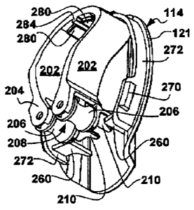
Another pair of top support tabs 280 is illustrated substantially at the apex
of the back
plate 114 and Configured to provide further support for the grip element 200
and
alignment. Without limiting the invention, alignment can be provided by the
top tabs 280
AMENDED SHEET
CA 02887992 2015-04-14
PCT/CA2013/050733
19 September 2014 19-09-2014
being slanted away from each other and/or by a slit 282 therebetween for an
appropriately configured grip element 200 extending into the slit 282, for
example a
spine 284 on the grip element 200 extending into the slit 282.
While not required, left and right snap-tabs 270 extend out beyond the short
wall 272
arid are illustrated positioned about the bottom support tabs 260, for example
enhancing
the strength of the bottom support tabs 260 and/or providing further side
alignment for
the toothbrush grip element 200.
Another optional crown tab 290 is illustrated which enables the use of the
back plate
114 and toothbrush grip 200 combination without the front enclosure 112. The
crown
tab 290, either by itself or in combination with the front cover 112 provides
an opposing
force while the toothbrush is inserted into the toothbrush holder 100. The
crown tab 290
can also counter the material deflection also employed in configuring the snap-
tabs 270.
When the crown tab 200 is not present the front cover 112 or the short wall
272
provides the opposing force while the toothbrush is inserted into the
toothbrush holder
100. For certainty the crown tab 290 need not be crown shaped.
In accordance with the second implementation of the first embodiment of the
proposed
solution, Figures 4A, 4B, 4C, 4D, and 4E illustrate a back plate 114 and
toothbrush grip
element 200 combination. The grip element 200 cooperates with the back plate
114 via
the bottom support tabs 260, the top support tabs 280 and optionally the crown
tab 290.
A pair of grip element tabs 210 rest on the bottom support tabs 260 of the
back plate
114. The illustrated grip element 200 includes a guide 264 cooperating with
the slit 282
between the top support tabs 280, without limiting the invention thereto. As
illustrated,
the back plate 114 and toothbrush grip element 200 combination can cooperate
to
enable the retention of a toothbrush without the front cover 112.
Preferably the toothbrush grip element 200 is configured to mechanically
engage the
toothbrush by clamping thereof. In accordance with one way of using the
combination,
the top support tabs 280 and crown tab 290 securely engage the grip element
200, for
21
AMENDED SHEET
CA 02887992 2015-04-14
PCT/CA2013/050733
19 September 2014 19-09-2014
example via snap-hooks or another separable engagement, and the toothbrush is
inserted in the grip element 200 against the .crown tab 290 (and/or the wall
272 if
present) and extracted from the grip element 200 against the support tabs
280/260. In
accordance with another way of using the combination, the top support tabs 280
operate as a hook on which the grip element 200 is hung, the grip element 200
being
removed from the back plate 114 during insertion and extraction of the
toothbrush
therefrom and replaced thereafter. References to a "cover body" herein are
intended to
include the toothbrush holder enclosure 110 as a whole.
For certainty the toothbrush grip element 200 engages the toothbrush, at least
the
toothbrush head, and is preferably removable from the enclosure for
sanitation. For
certainty, the invention is not limited to employing a removable toothbrush
grip element
200, in a disposable toothbrush holder 100 the toothbrush grip element 200 may
not be
removable. Disposable toothbrush holders 100 may be used in the hotel industry
or in a
hospital setting.
Figure 4C best illustrates the angled portion (116) of the back plate 114, in
combination
with the grip element 200, the angled portion (116) of the back plate 114 can
serve to
urge the grip element 200 toward the wall when a front cover 112 is not
employed
and/or account for toothbrushes having handles curved towards to wall when
inserted to
prevent the toothbrush handle from urging the toothbrush grip element 200 (and
the
toothbrush holder 100 as a whole) away from the wall.
Used with a front cover 112, the combination of the back plate 114 and grip
element
200 is configured to substantially align the travel path of the toothbrush
with the
enclosure opening 102. Figure 4B best illustrates ends 204 of the grip element
200
aligned with the bottom peripheral edge 121 of the back plate 114.
Clip
Figures 5A, 5B, 5C, 5D, 5E, 5F and 5G illustrate a first implementation of the
toothbrush
grip element 200 in accordance with the first embodiment of the proposed
solution.
22
AMENDED SHEET
CA 02887992 2015-04-14
PCT/CA2013/050733
19 September 2014 19-09-2014
The toothbrush grip element 200 includes a clip (200) and optionally alignment
elements 210/284 for example as described above. For certainty, the spine 284
is
present only in some implementations. As described hereinabove, the presence
of the
spine 284 does not imply use as the top support tabs 280 are optional For the
reminder of the description references to a "clip* include the toothbrush grip
element
200.
The clip 200 includes two opposing grip members 202, biased towards each
other,
cooperating to engage at least the tooth brush head. The clip 200 is
configured to grip
at least one of the toothbrush head and a toothbrush neck to hold the
toothbrush in the
toothbrush holder 100_ The grip members 202 can be biased against each other
being
manufactured from a resilient material, for example an elastic material not
limited to
polymers. A metal clip 200 could also provide the necessary resilient grip.
Form a
manufacturing perspective, polymers can be injection molded into the form of
the clip
200. The invention is not limited to a manufacturing technique.
In some embodiments the toothbrush is held in the toothbrush holder against
the normal
force of gravity.
The grip members 202 are separated by the insertion, and conversely by the
extraction,
of the head portion of the toothbrush.
Preferably the engagement area between the toothbrush as a whole and the
toothbrush
holder 100 as a whole is minimized. Preferably engagement is reduced to grip
members' 202 ends 204.
With reference to the first clip implementation, chiefly illustrated in
Figures 4A, 4B, 4C,
4D, 4E, 5A, 5B, 5C, 5D, 5E, SF and 5G, grip member ends 204 employ rollers
206.
Each roller 206 is configured to journal around a corresponding pivot
providing rolling
mechanical engagement between the clip 200 and the toothbrush. The head
portion of
23
AMENDED SHEET
CA 02887992 2015-04-14
PCT/CA2013/050733
19 September 2014 19-09-2014
the toothbrush can slide over the rollers 206 until the toothbrush snaps into
grip_ In
some implementations the toothbrush snaps into grip when the rollers 206
engage the
neck portion of the toothbrush.
For certainty, the invention is not limited to both grip members 202 being
resilient. A
single resilient grip member 202 impinging against a stiff grip member (202)
would work.
Preferably the rollers 206 form a channel-like guide 208 for the toothbrush
head and/or
neck. For example the rollers 206 can Include a circumferential notch 212
defining the
channel-like guide 208 therebetween
The circumferential notches 212 (either singly or in combination) present a
concave
depression at the bottom of the toothbrush holder 100 to the toothbrush head
leading
into the channel-like guide 208 between the gripping members 202.
Preferably the clip 200 includes a pair of clip tabs 210 extending from said
ends 204
generally away from the clip ends 204 in a desired orientation of the bristles
of the
toothbrush. Figures 4A, 48, 4C, 4D, 4E, 5A, 5B, 5C, 5D, 5E, 5F, 5G (and 6A,
6B, 6C,
CD, 6E, 6F, 6G) illustrate clip tabs 210 extending towards the back of the
toothbrush
holder 100 for inserting a toothbrush in with the bristles towards the wall.
The clip tabs
210 form a slit 214 between them. The slit 214 allows the bristles to pass
between the
tabs 210_
In accordance with the proposed solution, the clip tabs 210 are configured to
prevent
the toothbrush head from being inserted into the clip 200 while the toothbrush
head can
be inserted between the clip rollers 206 forcing a particular orientation of
the toothbrush.
While Figures 4A, 4B, 4C, 4D, 4E, 5A, 5B, 5C, 5D, 5E, 5F, 5G (and 6A, 6B, 6C,
6D, 6E,
6F, 6G) illustrate clip tabs 210 generally perpendicular to the direction of
travel of the
toothbrush head into the clip 200, the invention is not limited to blocking
toothbrush
travel. Alternatively, the dip tabs 210 can be configured to present a convex
overall
surface to the incoming toothbrush head deflecting the toothbrush head away.
As well
24
AMENDED SHEET
CA 02887992 2015-04-14
PCT/CA2013/050733
19 September 2014 19-09-2014
the clip tabs 210 can be in the same plane angled away or askew (Figures 11A,
11B,
11E and 11F) with respect to the direction of travel of the toothbrush head to
provide
deflection.
For certainty, the invention is not limited to the use of two rollers 206.
More than two
rollers 206 can be employed (not shown) which need not engage the neck of the
toothbrush. A single roller 206 impinging against the other grip member 202
would also
work. Employing rollers 206 enables use of toothbrushes with rubberized head
sides.
Figures 6A, 6B, 6C, 6D, 6E, 6F and 6G illustrate a second implementation of
the
toothbrush grip element 200 in accordance with the first embodiment of the
proposed
solution. For brevity description of structures and elements similar to the
first
toothbrush grip element 200 implementation is not repeated. The second clip
200
implementation does not employ rollers (206) per se, instead grip member ends
204
include opposing notches 212 defining the channel-like guide 208 between them.
The
notches 212 are configured to engage at least the toothbrush head via sliding
mechanical engagement. The notches 212 are further flared away from each other
presenting to an incoming toothbrush head a concave depression leading into
the
channel-like guide 208. Similar variations can be employed as with rollers
206,
variations in the number of notches 212 and material resilience of the grip
members
202.
Best illustrated in Figures 5F, 5C, 5D, 6C, 6D and 6G are tab 210 tips which
extend
beyond the toothbrush bristies, in combination with the notches 212, to space
the
bristles away from the back plate 114.
The invention is not limited to spacing the bristles away from the back plate
114 via tab
210 tips. Figures 4A, 4B, 4C, 40, 4E, 5A, 513, 5C, 5D, 5E, 5F, 5G, 6A, 66, 6C,
6D, 6E,
SF and 6G illustrate a clip 200 body deflected and extending towards the back
plate 114
in the direction of the bristles to space the bristles away from the back
plate 114.
26
AMENDED SHEET
CA 02887992 2015-04-14
PCT/CA2013/050733
19 September 2014 19-09-2014
For certainty the invention is not limited to the use of clip tabs 210 to
orient the
toothbrush in the toothbrush holder 100. Figures 7A, 7B, 7C and 7D illustrate
a third
implementation of the toothbrush grip element 200 in accordance with the first
embodiment of the proposed solution. For brevity description of structures and
elements similar to the first toothbrush grip element 200 implementation is
not repeated.
Toothbrush orientation is provided via a pair of shoulders 216. The grip
members 202
are shaped to flare away at the ends 204 presenting the concave depression to
the
incoming toothbrush head while the shoulders 216 are configured to provide a
restricted
passage allowing only the bristles to pass therebetween. The shoulders 216 can
be
flared also but with a tighter radius or even present edges to the incoming
toothbrush
head while defining a slit (214) therebetween for the bristles to pass through
and forcing
a toothbrush orientation with respect to the clip 200. The shoulders 216 can
include an
edge extending substantially parallel to the grip members 202 defining the
channel-like
guide 208 and/or include another edge extending substantially perpendicular to
the grip
members 202 defining the slit 214. For spacing the bristles away from the back
plate
114, shoulders 216 extend towards the back plate 114 more than the length of
the
bristles.
Notably in this implementation the spine alignment element 284 is replaced by
two
bumps 284 configured to engage corresponding openings (not shown) in the back
plate
114. The back plate 114 would also not require bottom support tabs 260.
Front Cover
Returning to the description of the front cover 112, the front cover is not
necessarily a
single piece. Figures 8A, 8B, 8C and 8D illustrate a first front cover element
120
generally but not necessarily opaque configured to engage the back plate 114
via an
adhesive. Preferably the cover 112, as illustrated in Figures 13B, 13D, 13E
and 13F,
engage the back plate 114 via a snap-fit engagement 270 as described herein
above.
26
AMENDED SHEET
CA 02887992 2015-04-14
PCT/CA2013/050733
19 September 2014 19-09-2014
Preferably the front cover 112 includes flared sides 103 best illustrated in
Figures 1B,
1C, 1D, 8B, 8C and 80 providing further guidance for the insertion of the
toothbrush
head into the toothbrush holder 100.
The front cover 112 can be provided with a window 130 into the toothbrush
holder
enclosure 110. Figures 9A, SB, 9C, 9D and 9E illustrate a second front cover
element
130, a window. For example the front cover window 130 can be tear drop shaped
and
can have features of shape and configuration adapted for snap-fit into the
first front
cover element 120.
Preferred Embodiment
In accordance with a fourth implementation of the first embodiment on the
proposed
solution Figures WA, 10B, 10C, 100, 10E, 1OF and 10G illustrate a reusable
sanitary
back plate 114. Features in common with the back plate 114 illustrated in
Figures 3A,
3B, 3C and 3D are not repeated.
The back plate 114 has an overall ovaloid shape with an interrupted peripheral
wall 272.
Via material choice, for example a polymer, and/or material thickness freely
extending
snap tabs 270 can be configured to provide more bending than the peripheral
wall 272
in engaging the front cover 112. The peripheral wall 272 can be configured to
provide
improved rigidity in engaging the front cover 112, whereas the snap tabs 270
act to pull
the front cover 112 shut towards the back plate 114.
As illustrated in Figure 10B an obround region 118 for affixing a double sided
tape or an
adhesive is provided on the back surface of the back plate 114, as well a
reinforced
opening is provided, as best illustrated in Figures 10A, 10B, 1OF and 10G, for
receiving
and engaging a fastener or a suction cup (not shown) for secure engagement
with a
bathroom wall.
In accordance with the fourth implementation, the support tabs 270 are
reinforced. The
bottom support tabs 260 are integral with the peripheral wall 272 as best
observable in
27
AMENDED SHEET
CA 02887992 2015-04-14
PCT/CA2013/050733
19 September 2014 19-09-2014
Figures 10A, 1OF and 10G. As best illustrated in Figures 10A, 10D and 10G the
top
support tabs 280 are reinforced via spines_
Figures 11A, 11B, 11C, 11D, 11E, 11F and 11G illustrate a reusable sanitary
toothbrush
grip element 200 or clamp 200. Features in common with the clamp 200
illustrated in
Figures 5A, 5B, 5C, 5D, 5E, 5F and 5G are not repeated.
The clamp 200 employs a pair of toothbrush grip element tabs 210 reinforced by
corresponding spines best illustrated in Figures 11B, 11E and 11F. It is noted
that the
clamp tabs 210 are not in the same plane as illustrated in Figures 11A, 11B,
11E and
11F.
Figures 12A, 128, 12C, 12D, and 12E illustrate an assembled reusable sanitary
toothbrush grip element 200 and back plate 114 combination. Features in common
with
the combination illustrated in Figures 4A, 4B, 4C, 4D, and 4E are not
repeated.
Figures 13A, 13B, 13C, 130, 13E and 13F illustrate a reusable sanitary front
cover
112/120_ Features in common with the front cover 120 illustrated in Figures
8A, 8B, 8C
and 80 are not repeated.
The front cover 120 lacks flared lateral walls (Figures 13A, 13B and 13E)
while a
reinforcing bridge 140 is provided between the two sides forming the window
(130).
The bridge 140 best illustrated in Figures 13A, 13B, 13C and 13F can also be
configured to participate in securing the window 130 as will be described
herein below.
A number of reinforcing spines are visible in Figures 13B and 13E providing
improved
rigidity around the bottom opening of the housing 110. Snap fit openings 170
for
mechanically engaging the snap fit tabs 270 of the back plate 114 are best
illustrated in
Figures 13B, 13D, 13E and 13F. The snap fit tabs 270 are guided by channels
172 best
illustrated in Figures 13B, 13E and 13F.
28
AMENDED SHEET
CA 02887992 2015-04-14
PCT/CA2013/050733
19 September 2014 19-09-2014
=
Figures 14A, 148, 14C, 14D, 14E and 14F illustrate a reusable sanitary front
cover
window 130. Features in common with the front cover window 130 illustrated in
Figures
9A, 9B, 9C, 9D and 9E are not repeated.
Notably the window 130 employs a bottom hook 132 for engaging the bridge 140
and a
top snap fit bump 134 for engaging to top of the front cover 120. Both hook
132 and
bump 134 act to releasably retain the window 130 in snap fit engagement with
the front
cover 120.
Integral Toothbrush Holder
In accordance with a second embodiment of the proposed solution, an integral
toothbrush holder enclosure 110 is illustrated in Figures 15A and 15B. The
toothbrush
holder 100 includes a generally flat back plate 114 configured to be affixed
to a wall.
The front cover 120 can be integral with, mountable to, fixedly adhered to,
etc. the back
plate 114 generally having a "U" shaped cross-section. Opposing resilient grip
members 202 of a clip 200 form the side walls of the toothbrush holder
enclosure 110.
Preferably the grip members 202 have flared ends (103) 204 to guide the
toothbrush
into the toothbrush housing enclosure 110.
Preferably a suction cup fastener or a suitable removable fastener is
provided, the
toothbrush holder enclosure 110 being adapted for travel.
Double Rollers
In accordance with a third embodiment of the proposed solution, another
toothbrush
holder clip 200 is illustrated in Figures 16A, 168, 16C, 16D, 16E and 16F. The
toothbrush holder clip 200 includes double rollers 206 configured to permit a
toothbrush
to be inserted into the toothbrush holder clip 200, and therefore by extension
in a
toothbrush holder enclosure 110, in either of two orientations: with the
bristles facing
forward or with the bristles facing away. While clip tabs (210) such as shown
in Figures
29
AMENDED SHEET
CA 02887992 2015-12-15
5C, 5D, 5E, 5F and 5G are not employed, the second pair of rollers 206 spaces
the
bristles, and therefore the toothbrush head, from coming in contact with
structures,
surfaces, objects, etc. external to the toothbrush holder clip 200 in either
orientation.
Opposing resilient grip members 202 of the clip 200 can form the side walls of
a
corresponding toothbrush holder enclosure 110. In
some implementations the
toothbrush enclosure 110 is configured to better cooperate with a toothbrush
having a
specific shape to reduce toothbrush positional play within the toothbrush
holder clip 200.
The illustrated toothbrush holder clip 200 is illustrated to have an "A" shape
which can
provide reduction in toothbrush positional play therein. Other details of an
optional back
plate (114) and an optional front cover (112), for example as mentioned
hereinabove,
are omitted for brevity.
While the invention has been shown and described with reference to preferred
embodiments thereof, it will be recognized by those skilled in the art that
additional
variants and modification are possible.