Language selection

Search

Patent 2888007 Summary

Third-party information liability

Some of the information on this Web page has been provided by external sources. The Government of Canada is not responsible for the accuracy, reliability or currency of the information supplied by external sources. Users wishing to rely upon this information should consult directly with the source of the information. Content provided by external sources is not subject to official languages, privacy and accessibility requirements.

Claims and Abstract availability

Any discrepancies in the text and image of the Claims and Abstract are due to differing posting times. Text of the Claims and Abstract are posted:

  • At the time the application is open to public inspection;
  • At the time of issue of the patent (grant).
(12) Patent: (11) CA 2888007
(54) English Title: FLOWERPOT COMPRISING ADJUSTABLE ARMS AND INDEPENDENT REMOVABLE SNAP PINS FOR COUPLING AND SUPPORTING TO RAILINGS, WALLS OR OTHER SUPPORTS
(54) French Title: POT DE FLEURS COMPRENANT DES BRAS AJUSTABLES ET DES GOUPILLES AMOVIBLES INDEPENDANTES POUR UN COUPLAGE A DES RAMPES, PAROIS OU AUTRES SUPPORTS
Status: Granted
Bibliographic Data
Abstracts

English Abstract


A flowerpot (100) comprising adjustable arms (104) and
independent removable snap pins (105) for safe coupling to
railings, walls or other supports comprising a container
(101) having a lateral edge (102), the adjustable arms
(104) comprising a vertical branch (104a) for engaging the
container (101) to the support and a horizontal branch
(104b) able to be coupled with a lower portion of the
lateral edge (102), characterized in that the lateral edge
(102) comprises at least two successive trough trenched
seats (106) able to be aligned and coupled with at least
two successive trough trenched seats (107) comprised in the
horizontal branch (104b) via at least one independent
removable snap pin (105).


French Abstract

L'invention concerne un pot de fleurs (100) comprenant des bras ajustables (104) et des goupilles amovibles indépendantes (105) pour un couplage sûr à des rampes, des parois ou d'autres supports comprenant un récipient (101) ayant un bord latéral (102), les bras ajustables (104) comprenant une branche verticale (104a) pour mettre le récipient (101) en prise avec le support et une branche horizontale (104b) apte à être accouplée à une partie inférieure du bord latéral (102), le pot de fleurs (100) étant caractérisé par le fait que le bord latéral (102) comprend au moins deux sièges d'auge creusés successifs (106) apte à être alignés et accouplés à au moins deux sièges d'auge creusés successifs (107) situés dans la branche horizontale (104b) par l'intermédiaire d'au moins une goupille amovible indépendante (105).

Claims

Note: Claims are shown in the official language in which they were submitted.

CLAIMS:
1. A flower pot (100) comprising adjustable arms
(104) and independent removable snap pins (105) for safe
coupling to a supportõ wherein the flowerpot comprises
a container (101) having a lateral edge (102), the
adjustable arms (104) comprising a vertical branch (104a)
for engaging the container (101) to the support and a
horizontal branch (104b) able to be coupled with a lower
portion of the lateral edge (102), characterized in that
the lateral edge (102) comprises at least two successive
trough trenched seats (106) able to be aligned and coupled
with at least two successive trough trenched seats (107)
comprised in the horizontal branch (104b) via at least one
of the independent removable snap pins (105).
2. A flowerpot (100) according to claim 1,
characterized in that the at least two successive trough
trenched seats (106) comprised in the lateral edge are
configured for internally fitting to the at least two
successive trough trenched seats (107) comprised in the
horizontal branch (104b).
3. A flowerpot (100) according to claim 1,
characterized in that the trough trenched seats (106, 107)
comprised in the lateral edge and comprised in the
horizontal branch are cylindrical.
- 9 -

4. A flowerpot (100) according to claim 1,
characterized in that the trough trenched seats (106)
comprised in the lateral edge are identical to each other.
5.A flowerpot (100) according to claim 1,
characterized in that the trough trenched seats (107)
comprised in the horizontal branch are identical to each
other.
6. A flowerpot (100) according to claim 1,
characterized in that at least one of the removable snap
pins (105) comprises an upper head (105a) and two lower
vertical appendices (105b) having bottom lateral
protrusions (105c) able to click into place at ends of the
trough trenched seats (107) comprised in the horizontal
branch.
7. A flowerpot (100) according to claim 1,
characterized in that at least one of the removable snap
pins (105) is made of plastic.
8. A flowerpot (100) according to claim 6,
characterized in that the at least one of the removable
snap pins (105) comprises a plastic plug (105d) between the
two lower vertical appendices (105b) and extending from a
bottom of the upper head (105a) to the bottom lateral
protrusions (105c) bottom of the vertical appendices
(105b) and has a prefixed length.
9. A flowerpot according to claim 1, wherein the
adjustable arms (104) and independent removable snap pins
(105) are for safe coupling of the flowerpot to a railing
or a wall.
-10-

Description

Note: Descriptions are shown in the official language in which they were submitted.


CA 02888007 2014-11-19
DESCRIPTION
"Flowerpot comprising adjustable arms and independent
removable snap pins for coupling and supporting to
railings, walls or other supports"
***
The present invention relates to a flowerpot
comprising adjustable arms and independent removable snap
pins for coupling and supporting to railings, walls or
other supports.
A flowerpot equipped with adjustable arms for coupling
and supporting to railings, walls or other supports is
described in the patent application N.
IT2003FI0001120030115published on 16-07-2004 and comprises
coupling arms which are adjustable to adapt to the
thickness of the support provided for supporting the
flowerpot. Moreover the described flowerpot comprises a
container provided with at least one retractable lower
support able to contact the outer face of the support. Each
coupling arm is perpendicular to the flowerpot, has a
vertical branch to embrace the support and a horizontal
branch perpendicular to the support, and is engageable in a
-1-

CA 02888007 2014-11-19
linearly adjustable position inside a corresponding seat
formed in the bottom portion of the edge of the flowerpot.
The seats comprised in the bottom portion of the edge of
the flowerpot present at least one or a series of snap pins
downwards oriented and also some lower trough protrusions.
The horizontal branch of each coupling arm form a plurality
of through seats for these snap pins and for these lower
protrusions in order to differently position the flowerpot
depending on the thickness of the support provided. In
addition a safety pin can be provided for being inserted
inside the trough protrusions previously coupled with the
corresponding trough seat of the coupling arm in order to
better guarantee the locking and the safety of the support
and for retaining against sliding.
The problem of the described flowerpot is that it is
difficult to easily manage the adjustments of position of
the flowerpot depending on the support thickness and to
quickly uncouple the flowerpot from the support.
Aim of the present invention is to provide a flowerpot
comprising adjustable arms and independent removable snap
pins for coupling and supporting to railings, walls or
other supports easy to disengage from the support and to
manage the adjustments of position on the support.
- 2 -

CA 02888007 2014-11-19
According to the present invention, a flowerpot
comprising adjustable arms and independent removable snap
pins for coupling and supporting to railings, walls or
other supports is realized, as defined in claim I.
For a better understanding of the present invention a
preferred embodiment is described, by way of non limitative
example, referring to the accompanying drawings, in which:
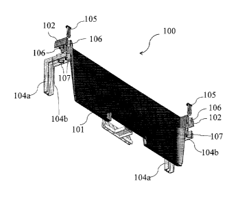
- Figure 1 shows a first schematic three-dimensional
view of an assembled flowerpot comprising adjustable arms
and independent removable snap pins for coupling and
supporting to railings, walls or other supports, according
to the invention;
- Figures 2a-2b show schematic three-dimensional views
of the assembly of the flowerpot comprising adjustable arms
and independent removable snap pins for coupling and
supporting to railings, walls or other supports, according
to the invention;
- Figure 3 shows a schematic three-dimensional section
view of the assembling of the flowerpot comprising
adjustable arms and independent removable snap pins for
coupling and supporting to railings, walls or other
supports, according to the invention;
- Figure 4 shows a schematic three-dimensional zoomed
section view of the assembling of the flowerpot comprising
-3-

CA 02888007 2014-11-19
adjustable arms and independent removable snap pins for
coupling and supporting to railings, walls or other
supporLs, according to the invention;
- Figure 5 shows a schematic three-dimensional zoomed
section view of the assembled flowerpot comprising
adjustable arms and independent removable snap pins for
coupling and supporting to railings, walls or other
supports, according to the invention;
- Figure 6 shows a schematic three-dimensional view of
an embodiment of the independent removable snap pins,
according to the invention.
Referring to those figures, and in particular to
figures 1 and 2, a flowerpot 100 comprising adjustable arms
and independent removable snap pins for coupling and
supporting to railings, walls or other supports is shown,
according to the invention. In more details, the flowerpot
100 comprises a container 101 having a lateral edge 102 and
a rear edge 103. The flowerpot 100 also comprised two
lateral arms 104, only one being shown in the figures, for
coupling and supporting the container 101 to railings,
walls or other supports, not shown in the figures. Each arm
104 comprises a vertical branch 104a for engaging the
container 101 to the support not shown and a horizontal
branch 104b to be coupled with the lower portion of the
-4-

CA 02888007 2014-11-19
lateral edge 102. In particular, the flowerpot 100 is
equipped with independent removable snap pins 105 for the
stable and safe fixing of the arms 104 to the lateral edge
102 of the container 101.
As better shown in the figures 3 and 4, the lateral
edge 102 of the container 101 comprises a plurality of
trough trenched seats 106 able to be aligned and coupled
with correspondent trough trenched seats 107 comprised in
the horizontal branch 104b of the arms 104.
More in details, advantageously, according to the
invention, the trough trenched seats 106 can enter inside
the trough trenched seats 107 so that the container 101 can
be coupled to the arms 104.
According to an aspect of the invention, the trough
trenched seats 106 and 107 are cylindrical.
Advantageously, according to the invention, a stable
and safe fixing of the container 101 coupled to the arms
104 is obtained inserting the removable snap pins 105
inside the trough trenched seats 106.
According to an aspect of the invention, as better
shown in the figure 5, the removable snap pins 105
comprises an upper head 105a and two lower vertical
appendices 105b having bottom lateral protrusions 105c and
contoured so that they insert and click into place to fix
-5-

CA 02888007 2014-11-19
the lateral edge 102 to the horizontal branch 104a of the
arms 104.
According to another aspect of the invention, the
removable snap pins 105 are made of plastics.
According to further aspect of the invention, each
removable snap pin 105 comprises a plastic plug 105d
between two lower vertical appendices 105b. The plug 105d
extends from the bottom of the upper head 105a to the
bottom lateral protrusions 105c bottom of the vertical
appendices 105b and has a length roughly equal to 15 mm.
Advantageously, according to the invention, the arm
104 can be moved at different positions depending on the
distance at which the flowerpot 100 has to be fixed on the
support. This is possible because all the trough trenched
seats 106 are identical each other and all the trough
trenched seats 107 are identical each other. Therefore,
each trough trenched seat 106 can be coupled with each
trough trenched seat 107.
Moreover, advantageously, according to the invention,
a single removable snap pins 105 can be inserted into the
trough trenched seats 106 and click into place at the end
of the trough trenched seats 107 to fix the lateral edge
102 to the horizontal branch 104a of the arms 104.
-6-

CA 02888007 2014-11-19
According to an aspect of the invention, only one
removable snap pin 105 is inserted per arm 104.
According to another aspect of the invention, a
plurality of removable snap pins 105 is inserted per arm
104.
Advantageously, according to the invention, the
flowerpot comprising adjustable arms and independent
removable snap pins for coupling and supporting to
railings, walls or other supports allows an easy
disengagement from the support.
Moreover, with the flowerpot comprising adjustable
arms and independent removable snap pins for coupling and
supporting to railings, walls or other supports it is
possible to easily manage the adjustments of flowerpot
position on the support.
At the end, the flowerpot comprising adjustable arms
and independent removable snap pins for coupling and
supporting to railings, walls or other supports according
to the invention is that it is adaptable to a plurality of
supports.
It should be clear that other modifications and
embodiments carried out to the described flowerpot
comprising adjustable arms and independent removable snap
pins for coupling and supporting to railings, walls or
-7-

CA 02888007 2014-11-19
other supports can be done falling within the scope of the
present invention, as defined in the appended claims.
-8-

Representative Drawing
A single figure which represents the drawing illustrating the invention.
Administrative Status

For a clearer understanding of the status of the application/patent presented on this page, the site Disclaimer , as well as the definitions for Patent , Administrative Status , Maintenance Fee  and Payment History  should be consulted.

Administrative Status

Title Date
Forecasted Issue Date 2020-06-23
(86) PCT Filing Date 2013-09-27
(85) National Entry 2014-11-19
(87) PCT Publication Date 2015-04-02
Examination Requested 2018-09-06
(45) Issued 2020-06-23

Abandonment History

There is no abandonment history.

Maintenance Fee

Last Payment of $125.00 was received on 2023-09-18


 Upcoming maintenance fee amounts

Description Date Amount
Next Payment if standard fee 2024-09-27 $347.00
Next Payment if small entity fee 2024-09-27 $125.00

Note : If the full payment has not been received on or before the date indicated, a further fee may be required which may be one of the following

  • the reinstatement fee;
  • the late payment fee; or
  • additional fee to reverse deemed expiry.

Patent fees are adjusted on the 1st of January every year. The amounts above are the current amounts if received by December 31 of the current year.
Please refer to the CIPO Patent Fees web page to see all current fee amounts.

Payment History

Fee Type Anniversary Year Due Date Amount Paid Paid Date
Application Fee $200.00 2014-11-19
Registration of a document - section 124 $100.00 2015-05-12
Maintenance Fee - Application - New Act 2 2015-09-28 $50.00 2015-07-21
Maintenance Fee - Application - New Act 3 2016-09-27 $50.00 2016-09-08
Maintenance Fee - Application - New Act 4 2017-09-27 $50.00 2017-08-02
Maintenance Fee - Application - New Act 5 2018-09-27 $100.00 2018-09-05
Request for Examination $400.00 2018-09-06
Maintenance Fee - Application - New Act 6 2019-09-27 $100.00 2019-09-09
Final Fee 2020-06-22 $150.00 2020-04-08
Maintenance Fee - Patent - New Act 7 2020-09-28 $100.00 2020-09-14
Maintenance Fee - Patent - New Act 8 2021-09-27 $100.00 2021-09-13
Maintenance Fee - Patent - New Act 9 2022-09-27 $100.00 2022-09-19
Maintenance Fee - Patent - New Act 10 2023-09-27 $125.00 2023-09-18
Owners on Record

Note: Records showing the ownership history in alphabetical order.

Current Owners on Record
BA.MA. SPA
Past Owners on Record
None
Past Owners that do not appear in the "Owners on Record" listing will appear in other documentation within the application.
Documents

To view selected files, please enter reCAPTCHA code :


To view images, click a link in the Document Description column. To download the documents, select one or more checkboxes in the first column and then click the "Download Selected in PDF format (Zip Archive)" or the "Download Selected as Single PDF" button.

List of published and non-published patent-specific documents on the CPD .

If you have any difficulty accessing content, you can call the Client Service Centre at 1-866-997-1936 or send them an e-mail at CIPO Client Service Centre.


Document
Description 
Date
(yyyy-mm-dd) 
Number of pages   Size of Image (KB) 
Amendment 2019-12-11 10 355
Claims 2019-12-11 2 60
Modification to the Applicant-Inventor 2020-03-20 6 123
Name Change/Correction Applied 2020-04-03 1 228
Final Fee 2020-04-08 5 108
Representative Drawing 2020-05-22 1 27
Cover Page 2020-05-22 1 62
Abstract 2014-11-19 1 22
Claims 2014-11-19 2 62
Description 2014-11-19 8 254
Drawings 2014-11-19 6 926
Representative Drawing 2015-05-01 1 27
Cover Page 2015-05-01 1 56
Request for Examination 2018-09-06 2 48
Examiner Requisition 2019-06-13 5 258
Assignment 2014-11-19 4 135
PCT 2014-11-19 10 616
Assignment 2015-05-12 4 262