Note: Descriptions are shown in the official language in which they were submitted.
CA 02888030 2015-04-15
WO 2014/189540
PCT/US2013/065209
1
METHOD AND APPARATUS FOR TREATING
OBSTRUCTIVE SLEEP APNEA (OSA)
Reference To Pending Prior Patent Application
This patent application claims benefit of pending
prior U.S. Provisional Patent Application Serial No.
61/714,596, filed 10/16/2012 by Peter J. Catalano for
METHOD AND APPARATUS FOR TREATING OBSTRUCTIVE SLEEP
APNEA (OSA) (Attorney's Docket No. CATALANO-1 PROV),
which patent application is hereby incorporated herein
by reference.
Field Of The Invention
This invention relates to surgical methods and
apparatus in general, and more particularly to
surgical methods and apparatus for treating
obstructive sleep apnea (OSA).
CA 02888030 2015-04-15
WO 2014/189540
PCT/US2013/065209
2
Background Of The Invention
Obstructive sleep apnea (OSA) is a sleep disorder
characterized by intermittent obstruction of the
supralaryngeal airway. Such intermittent obstruction
of the supralaryngeal airway is commonly caused by the
tongue falling backward in the throat while the
patient is sleeping so as to obstruct the airway. OSA
typically results in significant sleep disruption,
leading to excessive daytime drowsiness for the
patient. OSA may also lead to cardiovascular and
pulmonary disease due to the obstruction of the
supralaryngeal airway, particularly where the apneal
episodes last for 60 seconds or more.
Various treatments have been developed to address
OSA. The more conservative treatments include
prescribing weight loss to reduce tissue mass,
pharmaceutical treatments, the wearing of oral
appliances while sleeping, and the use of continuous
positive airway pressure (CPAP) devices to maintain
patency in the supralaryngeal airway. However, where
such conservative treatments are not effective, or
CA 02888030 2015-04-15
WO 2014/189540
PCT/US2013/065209
3
where such conservative treatments are not tolerated
by the patient, a surgical procedure may be needed to
prevent the tongue from obstructing the supralaryngeal
airway while the patient is sleeping. Unfortunately,
all of the surgical procedures developed to date
suffer from one or more significant disadvantages,
including poor performance, excessive trauma to the
patient (e.g., the tongue and/or jaw tissue),
excessive discomfort for the patient, etc.
Accordingly, a new method and apparatus is needed
to treat obstructive sleep apnea (OSA).
Summary Of The Invention
The present invention provides a new method and
apparatus for treating obstructive sleep apnea (OSA).
Significantly, this new method and apparatus is
minimally-invasive, whereby to minimize trauma to the
patient and discomfort for the patient.
In one preferred form of the invention, there is
provided apparatus for treating obstructive sleep
apnea, the apparatus comprising:
CA 02888030 2015-04-15
WO 2014/189540
PCT/US2013/065209
4
a tethering device comprising:
an elastic filament having a distal end and
a proximal end; and
a flexible memory head mounted to the distal
end of the elastic filament.
In another preferred form of the invention, there
is provided a method for treating obstructive sleep
apnea, the method comprising:
providing a tethering device comprising:
an elastic filament having a distal end and
a proximal end; and
a flexible memory head mounted to the distal
end of the elastic filament;
advancing the tethering device through the tongue
of a patient so that the flexible memory head of the
tethering device is disposed against the back of the
tongue and the elastic filament of the tethering
device extends through the tongue; and
securing the proximal end of the elastic filament
to the mandible of the patient under tension, whereby
CA 02888030 2015-04-15
WO 2014/189540
PCT/US2013/065209
to restrain rearward movement of the tongue while the
patient is sleeping.
Brief Description Of The Drawings
These and other objects and features of the
present invention will be more fully disclosed or
rendered obvious by the following detailed description
of the preferred embodiments of the invention, which
is to be considered together with the accompanying
drawings wherein like numbers refer to like parts and
further wherein:
Figs. 1 and 2 are schematic views showing a novel
tethering device formed in accordance with the present
invention;
Figs. 3 and 4 show further details of the elastic
filament of the novel tethering device shown in Figs.
1 and 2;
Figs. 5-8 show further details of the head of the
novel tethering device shown in Figs. 1 and 2, wherein
Fig. 5 shows the complete head, Fig. 6 shows the head
with its head stiffener and overcoat removed, Fig. 7
CA 02888030 2015-04-15
WO 2014/189540
PCT/US2013/065209
6
shows the head with its head stiffener in place but
the overcoat removed, and Fig. 8 shows the head
stiffener alone;
Figs. 9-12 show novel instrumentation for
deploying the novel tethering device shown in Figs. 1
and 2;
Figs. 13-33 show one preferred method (and
associated apparatus) for deploying the novel
tethering device shown in Figs. 1 and 2 using the
novel instrumentation shown in Figs. 9-12;
Figs. 34-36 show an alternative head for the
novel tethering device shown in Figs. 1 and 2;
Figs. 37 and 38 show another alternative head for
the novel tethering device shown in Figs. 1 and 2;
Fig. 39 shows still another alternative head for
the novel tethering device shown in Figs. 1 and 2;
Fig. 40 shows yet another alternative head for
the novel tethering device shown in Figs. 1 and 2; and
Figs. 41-43 show various configurations of a
lighted corridor trocar which may be used in
accordance with the present invention.
CA 02888030 2015-04-15
WO 2014/189540
PCT/US2013/065209
7
Detailed Description Of The Preferred Embodiments
The present invention provides a new method and
apparatus for treating obstructive sleep apnea (OSA).
Significantly, this new method and apparatus is
minimally-invasive, whereby to minimize trauma to the
patient and discomfort for the patient.
More particularly, in accordance with the present
invention, and looking now at Figs. 1 and 2, there is
provided a novel tethering device 5 for restraining
rearward movement of the tongue so as to prevent the
tongue from obstructing the supralaryngeal airway
while the patient is sleeping, whereby to treat
obstructive sleep apnea. As seen in Figs. 1 and 2,
tethering device 5 generally comprises an elastic
filament 10 having a head 15 on its distal end and a
series of enlargements 20 (e.g., frustoconical
enlargements) on its proximal end.
Figs. 3 and 4 show further details of elastic
filament 10. In general, elastic filament 10
comprises an elastomeric material having means 25 on
CA 02888030 2015-04-15
WO 2014/189540
PCT/US2013/065209
8
its distal end for mounting head 15 to the distal end
of the filament, and the aforementioned enlargements
20 (e.g., frustoconical enlargements) on its proximal
end. As will hereinafter be discussed, enlargements
20 (disposed on the proximal end of elastic filament
10) facilitate securing the proximal end of elastic
filament 10 to a bone anchor secured to the lower
mandible of the patient, as will hereinafter be
discussed in further detail.
Figs. 5-8 show further details of head 15. In
general, head 15 comprises a large disk-like structure
30 (Fig. 5) formed out of a relatively soft, pliable,
atraumatic material. This large disk-like structure
30 has a patterned recess 35 (Fig. 6) formed in its
proximal side for receiving a head stiffener 40 (Figs.
7 and 8), whereby to provide head 15 with appropriate
structural integrity for its intended purpose (i.e.,
to provide a bearing structure at the back of the
tongue so as to allow tethering device 5 to restrain
rearward movement of the tongue, as will hereinafter
be discussed). An overcoat 45 (Fig. 5) is set atop
CA 02888030 2015-04-15
WO 2014/189540
PCT/US2013/065209
9
head stiffener 40 so as to seal head stiffener 40
within patterned recess 35 of the large disk-like
structure 30. In one preferred form of the invention,
patterned recess 35 and head stiffener 40 each have a
multi-lobe configuration (e.g., four lobes as shown,
or three lobes, or two lobes, or five lobes, etc.).
And, in one preferred form of the invention, head
stiffener 40 is preferably formed out of superelastic
material, e.g., Nitinol or another superelastic metal
alloy, whereby to permit head stiffener 40 to be
significantly deformed and thereafter elastically re-
form, as will hereinafter be discussed. It will be
appreciated that, on account of the foregoing
construction, head 15 effectively comprises a flexible
memory structure disposed at the distal end of elastic
filament 10, and this flexible memory head provides a
sufficient bearing structure to restrain rearward
movement of the tongue, as will hereinafter be
discussed.
Looking now at Figs. 9-12, there is shown
preferred instrumentation for deploying tethering
CA 02888030 2015-04-15
WO 2014/189540
PCT/US2013/065209
device 5 in the anatomy of a patient. In general,
this instrumentation comprises a corridor sheath 50
having a lumen 51 extending therethrough (Fig. 9), a
corridor trocar 55 terminating in a sharp distal tip
56 (Fig. 10), an outer inserter tube 60 having a lumen
61 extending therethrough (Fig. 11), and an inner
inserter tube 62 having a lumen 63 extending
therethrough and having a head 64 attached to its
proximal end. As will hereinafter be discussed below,
corridor trocar 55 is sized to fit within lumen 51 of
corridor sheath 50, outer inserter tube 60 is sized to
fit within lumen 51 of corridor sheath 50, inner
inserter tube 62 is sized to fit within lumen 61 of
outer inserter tube 60, and lumen 63 of inner inserter
tube 62 is sized to receive the elongated body
(sometimes hereinafter referred to as the "shaft") of
elastic filament 10.
The novel tethering device 5 of Figs. 1-8 is
intended to be deployed in the native anatomy of a
patient (Fig. 13), preferably using the corridor
sheath 50, corridor trocar 55, outer inserter tube 60
CA 02888030 2015-04-15
WO 2014/189540
PCT/US2013/065209
11
and inner inserter tube 62 of Figs. 9-12, so as to
restrain rearward movement of the tongue T and thereby
prevent tongue T from obstructing the supralaryngeal
airway A of the patient while the patient is sleeping,
whereby to treat obstructive sleep apnea. Also shown
in Fig. 13 is the lower mandible M of the patient.
More particularly, and looking now at Fig. 14,
corridor sheath 50, having corridor trocar 55 disposed
therein so that the sharp distal tip 56 of corridor
trocar 55 extends out the distal end of corridor
sheath 50, is inserted upward and backward through
tongue T. Distal movement of the assembled corridor
sheath 50/corridor trocar 55 continues until the
distal end of corridor sheath 50 emerges through the
back of tongue T.
Then corridor trocar 55 is removed, from
posterior to anterior (i.e., proximally), leaving
corridor sheath 50 extending upward and backward
through tongue T, in the manner shown in Fig. 15.
CA 02888030 2015-04-15
WO 2014/189540
PCT/US2013/065209
12
Next, outer inserter tube 60 and inner inserter
tube 62 are used to advance tethering device 5 through
lumen 51 of the emplaced corridor sheath 50.
More particularly, tethering device 5 is loaded
into outer inserter tube 60 by folding head 15 towards
the proximal end of the "shaft" of elastic filament 10
so that the lobes of head 15 are substantially aligned
with, and substantially parallel to, the shaft of
elastic filament 10 (Fig. 16), or folding head 15 away
from the proximal end of the shaft of elastic filament
so that they fold onto themselves and extend beyond
the distal end of the shaft of elastic filament 10
(Fig. 17). Then inner inserter tube 62 is slid over
the proximal end of elastic filament 10 of tethering
device 5, in a distal-to-proximal direction, until the
folded head 15 of tethering device 5 is contacted and
engaged by the distal end of inner inserter tube 62
(Fig. 18). It will be appreciated that, at this
point, head 15 of tethering device 5 is folded and
housed within outer inserter tube 60 and the shaft of
elastic filament 10 extends back through lumen 63 of
CA 02888030 2015-04-15
WO 2014/189540
PCT/US2013/065209
13
inner inserter tube 62 (which is itself disposed
within lumen 61 of outer inserter tube 60).
It will be appreciated that as a result of the
foregoing construction and assembly, if and when head
64 of inner inserter tube 62 should thereafter be
moved distally relative to outer inserter tube 60, the
folded head 15 of elastic filament 10 will be ejected
out of the distal end of outer inserter tube 60,
whereby to deploy head 15 to its original pre-folded
shape (Figs. 19-21).
It should be appreciated that the assembly shown
in Fig. 18 may be assembled at the time of use (e.g.,
on a "back table" in an operating room) or at the time
of manufacture (in which case it is packaged and
shipped in the form shown in Fig. 18).
This "tube-over-tube" assembly (Fig. 18) allows
tethering device 5 to be quickly and easily advanced
through lumen 51 of the emplaced corridor sheath 50
(Fig. 15), such that tethering device 5 can be
properly positioned in the patient. More
particularly, with head 15 of tethering device 5
CA 02888030 2015-04-15
WO 2014/189540
PCT/US2013/065209
14
folded and housed within lumen 61 of outer inserter
tube 60, and with the shaft of elastic filament 10
extending back through lumen 63 of inner inserter tube
62, the assembly of outer inserter tube 60, tethering
device 5, and inner inserter tube 62 is inserted into
the proximal end of lumen 51 of corridor sheath 50 and
then advanced, in a proximal-to-distal manner (Fig.
22).
This proximal-to-distal movement continues until
the distal end of outer inserter tube 62 emerges from
the distal end of corridor sheath 50 on the back side
of the tongue (Fig. 23).
Then head 64 of inner inserter tube 62 is moved
further distally until it rests against the proximal
end of corridor sheath 50 (Fig. 24), causing the
folded head 15 to emerge from the distal end of outer
inserter tube 60, whereupon head 15 will unfold back
to its original pre-folded shape due to the memory
effects of stiffener 40 in head 15 (Fig. 24).
In this respect it will be appreciated that by
forming head stiffener 40 out of a superelastic
CA 02888030 2015-04-15
WO 2014/189540
PCT/US2013/065209
material (e.g., Nitinol or another superelastic metal
alloy), the folding of head 15 in outer inserter tub
60 is facilitated, and the unfolding of head 15 as it
emerges from the distal end of outer inserter tube 60
will also be facilitated.
In other words, outer inserter tube 60 and inner
inserter tube 62 are used together to advance the
folded head 15 of tethering device 5 through corridor
sheath 50 (and hence through tongue T), with the head
15 of the tethering device being held in a folded
condition within outer inserter tube 60 until the
distal end of outer inserter tube 60 emerges from the
distal end of corridor sheath 50. Inner inserter tube
62 is then used to eject folded head 15 out of the
distal end of outer inserter tube 60, whereupon folded
head 15 unfolds, with the unfolded head 15 residing on
the far side of tongue T.
Once head 15 is unfolded and deployed on the far
side of tongue T, inner inserter tube 62 and outer
inserter tube 60 are withdrawn proximally back through
corridor sheath 50, leaving elastic filament 10
CA 02888030 2015-04-15
WO 2014/189540
PCT/US2013/065209
16
extending back through lumen 51 of corridor sheath 50
(and hence elastic filament 10 extending back through
tongue T).
Then corridor sheath 50 is removed, leaving
tethering device 5 extending through tongue T, with
head 15 of tethering device 5 sprung open adjacent the
back of tongue T (Fig. 25).
Next, a bone anchor 65 is deployed in the lower
mandible M (Fig. 26). Bone anchor 65 may be a so-
called screw-type bone anchor or another type of bone
anchor (e.g., a barb-type bone anchor, etc.). As seen
in Figs. 27-32, bone anchor 65 preferably includes a
mount 66 for mounting the proximal end of elastic
filament 10 to the bone anchor. Mount 66 preferably
has a hole 67 and a slot 68 formed therein. A seat 69
is preferably formed at the end of slot 68. Mount 66
preferably also includes a hole 70 for securing mount
66 to bone anchor 65 via a screw 71. Mount 66 may be
mounted to bone anchor 65 either before bone anchor 65
is deployed in mandible M or after bone anchor 65 has
been deployed in mandible M.
CA 02888030 2015-04-15
WO 2014/189540
PCT/US2013/065209
17
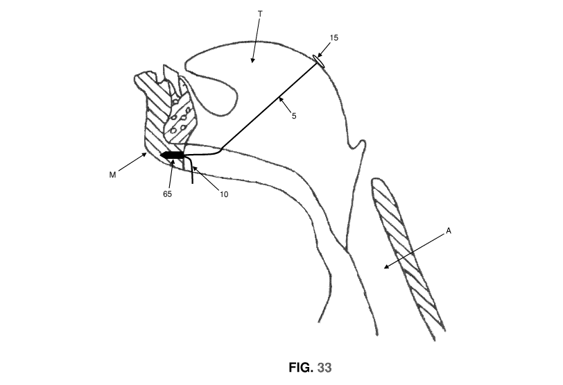
After bone anchor 65 (and mount 66) have been
secured to lower mandible M, elastic filament 10 of
tethering device 5 is secured to mount 66 of bone
anchor 65 under tension (Fig. 33) so that head 15 of
tethering device 5 is pulled flush against the back
surface of the tongue and supports the tongue from
backward displacement when at rest. More
particularly, elastic filament 10 of tethering device
is secured to bone anchor 65 by passing enlargements
20 (e.g., frustoconical enlargements) on the proximal
end of filament 10 through hole 67 of mount 66 and
then moving filament 10 laterally along slot 68 so as
to seat an enlargement 20 in seat 69 of mount 66.
It will be appreciated that, as a result of the
foregoing, tethering device 5 essentially elastically
tethers the back of tongue T to a fixed anatomic point
(i.e., the lower mandible M, where bone anchor 65 is
set) using an elastic filament 10 terminating in an
atraumatic head 15. With tongue T tethered in this
manner, normal function of the tongue is retained
(e.g., during talking and swallowing), yet rearward
CA 02888030 2015-04-15
WO 2014/189540
PCT/US2013/065209
18
movement of the tongue is restrained while the patient
is sleeping, thereby preventing the tongue from
obstructing the supralaryngeal airway A while the
patient is sleeping, and thus treating obstructive
sleep apnea. And by forming head 15 out of a
relatively soft, pliable, atraumatic material,
reinforced by an internal head stiffener 40, head 15
will provide the necessary structural integrity while
being atraumatic to the tissue. Furthermore, by
virtue of the low profile of head 15 vis-a-vis the
back of the tongue, the head of the tethering device
does not interfere with swallowing action or
breathing.
In the preferred form of the invention, and
looking now at Figs. 1, 2 and 5-7, a plurality of
holes 71 are formed on the large disk-like structure
30 of head 15. Holes 71 can be advantageous in the
event that the tethering device 5 should fail and head
15 should be aspirated, since holes 71 can prevent
head 15 from completely obstructing an air passageway
CA 02888030 2015-04-15
WO 2014/189540
PCT/US2013/065209
19
(which may sometimes also be referred to as an
"airway").
Alternatively, and looking now at Fig. 35-36 (or
Figs. 37 and 38), head 15 can be formed with the
material between the lobes removed, e.g., at 75,
whereby to further facilitate head folding and to
further reduce the risk that head 15 could obstruct an
airway in the event of device failure and aspiration.
If desired, the lobes can be rounded off so as to
reduce device mass and so as to render them even more
atraumatic to the tissue.
If desired, and looking now at Fig. 39 (or Fig.
40), a rim 80 of material can extend across the open
space 75 which is located between the lobes, at the
periphery of the head, so as to provide additional
head integrity, and rendering the head even more
atraumatic, while still protecting against airway
blockage in the event of device failure and
aspiration.
In some circumstances it can be desirable to
provide visual guidance to assist in proper placement
CA 02888030 2015-04-15
WO 2014/189540
PCT/US2013/065209
of tethering device 5 within tongue T. Thus, in one
preferred form of the invention, tethering device 5 is
set within tongue T using X-ray visualization.
In another preferred form of the invention,
proper placement of tethering device 5 is achieved
using a light-emitting trocar. More particularly, and
looking now at Fig. 41, corridor trocar 55 may include
a light source 85 disposed within its distal end, and
a window 90 for permitting light from light source 85
to project out the distal end of corridor trocar 55.
Alternatively, and looking now at Figs. 42 and 43),
the light source may be disposed at the proximal end
of corridor trocar 55 and light from the light source
delivered to the distal end of corridor trocar 55 by
means of an optical fiber 95 (or a light pipe, etc.).
In this form of the invention, light is projected from
the distal end of corridor trocar 55 while the
corridor trocar (and its associated corridor sheath
50) are advanced through tongue T - as this occurs, a
scope is used to observe the back of the tongue and,
as the trocar nears the surface of the tissue, the
CA 02888030 2015-04-15
WO 2014/189540
PCT/US2013/065209
21
light from corridor trocar 55 is used to gauge proper
positioning of corridor trocar 55 (and hence its
associated corridor sheath 50), whereby to ensure
subsequent proper positioning of tethering device 5
within the tongue and tongue base. It is anticipated
that proper placement of head 15 will be important to
the effectiveness of device 5.
Modifications
While the present invention has been described in
terms of certain exemplary preferred embodiments, it
will be readily understood and appreciated by those
skilled in the art that it is not so limited, and that
many additions, deletions and modifications may be
made to the preferred embodiments discussed herein
without departing from the scope of the invention.