Note: Descriptions are shown in the official language in which they were submitted.
CA 02888130 2017-01-11
MEDICAL AMPLIFIER ISOLATION
[0001]
TECHNICAL FIELD
[0002] This disclosure relates to medical amplifier isolation systems and
method.
BACKGROUND
[0003] Medical amplifiers can be implemented for a variety of devices used
in
connection with patient treatment procedures and/or medical diagnoses. Medical
amplifiers can be configured in a manner to isolate a patient from any
possible
contact with a power source, such as including line voltage and earth ground.
Isolation can be implemented in a variety of ways, such as magnetic or optical
isolation, to pass signals between a control system and portions of the device
that
might contact the patient. Some types of isolation can result in the medical
amplifier
being more susceptible to radiated noise, such as line frequency noise, based
on the
patient ground not being coupled with earth ground. In these situations, a
substantially large common-mode voltage with respect to earth ground can be
generated, such that the common-mode voltage generates a current flow from the
patient to earth ground via a parasitic capacitance, thus generating a
differential
voltage that cannot be rejected by the medical amplifier.
SUMMARY
[0004] This disclosure relates to isolation for a medical amplifier system.
[0005] As an example, a medical amplifier system includes a patient
circuitry
stage configured to receive electric signals from the patient and provide
corresponding output signals. The patient circuity stage can include an
electrical
connection to a patient ground. The system also includes control circuitry
configured
to process the corresponding output signals. An isolation system can be
configured
to electrically isolate the patient circuitry and the control circuitry by
including a
1
CA 02888130 2015-04-10
WO 2014/059308
PCT/US2013/064595
functional ground that is capacitively coupled to the patient ground but
electrically
isolated from the control circuitry.
[0006] As another example, an apparatus can include an isolation system
configured to be connected between and provide electrical isolation between
patient-
side circuitry and other circuitry. The isolation system can include a patient
isolation
stage comprising at least one signal input configured to connect to a signal
path of
the patient-side circuitry and a power input configured to connect to a power
path of
the patient circuitry. At least one other isolation stage can be connected
between
the patient isolation stage and the other circuitry. Such other isolation
stage can
include a corresponding signal path configured to communicate signals from the
signal path of the patient-side circuitry signal to the other circuitry and a
separate
power path configured to provide input power from the other circuitry to the
power
path of the patient isolation stage. A capacitive coupling is connected across
the
patient isolation stage between a patient ground of the patient-side circuitry
and a
functional ground of the isolation system, the other isolation stage being
configured
to electrically isolate the functional ground from the other circuitry.
BRIEF DESCRIPTION OF THE DRAWINGS
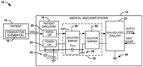
[0007] FIG. 1 depicts an example of a medical amplifier system implementing
an isolation system.
[0008] FIG. 2 depicts an example diagram of medical amplifier system that
can be implemented.
[0009] FIG. 3 depicts another example diagram of a medical amplifier
system.
DETAILED DESCRIPTION
[0010] This disclosure relates to medical amplifier isolation systems and
related methods. As an example, a medical amplifier system can include an
isolation system that includes multiple stages of isolation between patient
circuitry,
including an amplifier, and non-isolated control and processing circuitry. A
capacitance can be provided across a patient-side isolation barrier, such as
by
capacitively coupling a patient ground and an isolated functional ground. The
capacitance between such grounds can establish a lower impedance path for
noise
current than parasitic capacitors to earth ground in the amplifier system. The
2
CA 02888130 2015-04-10
WO 2014/059308
PCT/US2013/064595
medical amplifier thus can substantially reduce the magnitude of current
flowing
between the patient and earth ground via a parasitic capacitance, resulting in
an
increased signal to noise ratio, while also being capable of meeting or
exceeding
standard requirements for isolation and leakage current.
[0011] FIG. 1 depicts an example of a system 10 that includes medical
amplifier system 12. The medical amplifier system 12 can be implemented in a
variety of medical applications for administering treatment to or obtaining
diagnostic
information from a patient 14, for example. The medical amplifier system 12
includes a patient circuitry stage 16 that can be coupled to the patient 14
via
electrically conductive leads terminating to sensor elements 18, such as
electrodes
or probes. The sensor elements can be passive sensor electrodes or active
circuit
components can also be implemented at the electrodes.
[0012] The patient circuitry stage 16 can thus receive signals SGNLpi-NT
from
the patient 14 via the sensor elements 18. There can be any number of sensor
elements 18, and the patient circuitry 16 can include circuitry for processing
signals
provided by each such conductors. The sensor elements 18 can be non-invasive
(e.g., positioned on the surface of the patient's body) and/or be invasive
(e.g.,
percutaneously or otherwise positioned within the patient's body).
[0013] In the schematic example of FIG. 1, the patient circuitry stage 16
includes signal circuitry 20 and power circuitry 22. The patient circuitry 16,
including
the signal circuitry 20 and power circuitry 22, can operate electrically
relative to a
patient ground 24. The power circuitry 22 can be configured to deliver
electrical
power (e.g., regulated DC power) to the patient circuitry 16, including the
signal
circuitry 20. While for purposes of ease of explanation the signal circuitry
20 and the
power circuitry 22 are demonstrated as separate blocks, it is to be understood
that
power and processing circuitry can be structurally integrated together in
other
examples.
[0014] The signal circuitry 20 can include one or more amplifiers that can
be
configured to amplify each of the patient signals SGNLpi-NT, such as
anatomically
generated electrical impulses. The signal circuitry 20 can be configured to
amplify
the signals SGNI-pi-NT and provide corresponding amplified signals SGNLAmp to
one
or more corresponding non-isolated circuitry 32. The non-isolated circuitry 32
can
operate electrically relative to an earth ground that is electrically isolated
from the
patient ground 24. Specifically, the amplifier system 12 includes an isolation
system
3
CA 02888130 2015-04-10
WO 2014/059308
PCT/US2013/064595
25 configured to electrically isolate the patient circuitry from the non-
isolated circuitry
32.
[0015] As a further example, the signal circuitry 20 can be configured
(e.g., by
including an analog-to-digital converter) to provide the amplified signals
SGNLAmp as
digital signals. As an example, the non-isolated circuitry 32 can include
processing
circuitry, such as to implement signal conditioning and filtering on the
amplified
signals SGNLAmp provided by the isolated patient circuitry 16. The non-
isolated
circuitry 32 can in turn provide processed version of the amplified signals
SGNLAmP
for subsequent processing (e.g., by an EC mapping hardware and software and/or
other diagnostic equipment) via the signal path.
[0016] In other examples, the non-isolated circuitry 32 can generate
control
signals to the patient circuitry stage 16 and/or the patient 14. For example,
the
control signals can be utilized to configure the patient circuitry stage 16,
including the
signal circuitry 20. As another example, the control signals may be used to
control
delivery of therapy to the patient 14 across the isolation system 25. Control
signals
can also be generated by the patient circuitry 16 and provided to the non-
isolated
circuitry 32 via the signal path through the isolation system 25.
[0017] The isolation system 25 is configured to electrically isolate the
patient
circuitry 16 from the non-isolated circuitry 32. The isolation system 25 can
include
more than one isolation barrier 26 and 30. Each isolation barrier 26, 30 can
be
configured to provide one type of isolation for data/information signals
(e.g., optical
isolation) and another type of electrical isolation (e.g., magnetic isolation)
for power
signals that are being provided between the patient circuitry and the non-
isolated
circuitry 32. Other types of isolation can be implemented for communication of
data
and power between the patient circuitry and the non-isolated circuitry.
[0018] In the example of FIG. 1, the non-isolated circuitry 32 can be
coupled
to receive input power from a power source (not shown - e.g., approximately
120
VAC/60 Hz or 230 VAC/50 Hz or regulated DC power). For instance, the non-
isolated circuitry 32 can be connected between a line voltage and earth ground
36.
The isolation system 25 thus is configured to provide electrical isolation
between the
patient 14 and the power source, such that a patient ground 24 is not
electrically
coupled with earth ground 36 to which the circuitry 32 is connected. The data
and
information signals (e.g., including the signals SGNLAmp) and power can thus
be
communicated across the isolation system 25 between the non-isolated circuitry
32
4
CA 02888130 2015-04-10
WO 2014/059308
PCT/US2013/064595
and the patient circuitry 16. In the example of FIG. 1, while the non-isolated
circuitry
32 is demonstrated as coupled to earth ground 36, it is to be understood that
the
low-voltage rail reference could be a variety of low-voltage amplitudes
electrically
isolated from patient ground 24, and is not limited to earth ground.
[0019] In some circumstances, the isolation system 25 can render the
medical
amplifier system 12 more susceptible to radiated noise, such as line frequency
noise
or other noise that exists within the bandwidth being measured. This
susceptibility is
based on the isolation of the patient ground 24 with respect to earth ground
36.
Isolating the patient 14 can result in the patient ground voltage potential to
"float",
such as based on electric fields acting upon the patient 14, and thus inducing
a
leakage current to flow from the patient ground 24 to earth ground 36 via a
parasitic
capacitance Cp. The parasitic capacitance Op is distributed around the device
and
the cabling, so currents through any part of the device will vary. As a
result, the
patient circuitry stage 16 can generate a substantially large common-mode
voltage
with respect to earth ground 36. The common-mode voltage can generate a
common-mode current that can induce a differential voltage in the amplified
signals
SGNLAmp that cannot be rejected by the medical amplifier system 12. For
example,
the common-mode current flow can instantiate a differential voltage with
respect to
input resistors associated with the signal circuitry 20, which can be
transmitted as
noise in the signals SGNLAmp. The amount of current flow leakage may be
reduced
by employing matched resistors, but this alone still tends to be insufficient
for
achieving high common mode rejection (e.g., greater than -100 dB, such as
about -
140 dB or more).
[0020] To substantially mitigate the common-mode current flow, the medical
amplifier system 12 includes a capacitive coupling CGND connected across the
patient isolation system 25 between the patient ground 24 and a functional
ground
28 residing between separate isolation stages in the isolation system. For
example,
the capacitive coupling CGND can be configured as one or more physical
capacitors
having a capacitance that is greater than the parasitic capacitance Cp. As a
result,
the capacitive coupling CGND can provide a lower impedance path across the
isolation system 25. The low impedance path effectively causes the functional
isolation stage to float at approximately the same voltage as the patient
isolation
stage. Such a low-impedance path substantially reduces a voltage difference
across
the parasitic capacitance Cp. As a result, a substantially large portion of
the leakage
CA 02888130 2015-04-10
WO 2014/059308
PCT/US2013/064595
current that can cause the common-mode current can flow through the capacitive
coupling CGND instead of the parasitic capacitance Cp, resulting in
significantly
reduced leakage current and correspondingly reduced differential voltage at
the input
of the signal circuitry 20. As a further result, the sensed signals at the
input of the
amplifier exhibit an improved common mode rejection ratio (e.g., by about 20
dB or
more).
[0021] Additionally, the total amount of leakage current in the system 10
is
about the same as a system having a single isolation barrier. This is because
the
magnitude of the leakage current is determined by the size of the parasitic
capacitors
at the patient stage, and across the final isolation barrier to earth ground.
Since the
size of the parasitic capacitors does not change when a functional isolation
stage is
added, such as disclosed herein, patient safety is not compromised.
[0022] FIG. 2 depicts a schematic diagram of an example of a medical
amplifier system 50 that can be implemented. The amplifier system 50 includes
a
patient-side circuitry stage 52, such as can correspond to the patient
circuitry stage
16 of the medical amplifier system 12 in the example of FIG. 1. Therefore,
reference
can be made to FIG. 1 in the following description of the example of FIG. 2.
[0023] The patient circuitry stage 52 includes an amplifier 54 that is
configured
to generate an amplified signal SGNLAmp in response to a patient input signals
SGNLpi-Nr. The patient signals SGNLpi-NT can correspond to one or more
electrical
signals measured from the patient, such as via conductive elements (e.g.,
sensor
electrodes) that are coupled to the patient. In some examples, the conductive
elements can be electrodes distributed across a patient's torso, such as non-
invasively covering the entire torso or a predetermined portion thereof. For
instance,
the electrodes can be arranged on the patient's torso, such as for acquiring
electrical
signals for electrocardiographic mapping or for gathering electrocardiograph
(ECG)
or electroencephalograph (EEG) diagnostics. Additionally, each electrode can
define a respective input channel that provides a corresponding patient signal
SGNLpi-NT to a respective amplifier 54, each of which amplifiers can be
electrically
isolated based on the teachings herein. The amplifier 54 as well as other
patient-
side circuitry 52 can be powered by patient-side power circuitry 62 that is
supplied
power via a power path of an isolation system 63 such as disclosed herein. The
power circuitry 62 thus can establish a high voltage rail (e.g., a regulated
voltage)
demonstrated as V+ that is relative to a low voltage rail corresponding to
patient
6
CA 02888130 2015-04-10
WO 2014/059308
PCT/US2013/064595
ground 60. The power circuitry 62 can similarly also, for example, establish a
negative voltage rail V- (not shown) relative to the patient ground 60.
[0024] In the simplified example of FIG. 2, the amplifier 54 can include a
first
input resistor R1 coupled to a non-inverting input and a second input resistor
R2
coupled to an inverting input. The amplifier 54 thus provides an amplified
output
signal SGNLAmp to signal processing and control circuitry (not shown, but see,
e.g.,
circuitry 32 of FIG. 1) through two or more isolation stages, demonstrated at
64 and
66. Each isolation stage 64, 66 can be configured to communicate power and
data
in a manner that affords electrical isolation between the input and output
thereof.
Since the manner of electrical isolation being implemented can vary according
to
design considerations and application requirements, the isolation for data and
power
are demonstrated as dotted lines extending across the blocks corresponding to
the
isolation barriers 64 and 66. As mentioned above, for example, optical
isolation can
be utilized for communicating data, such as by employing digital optical
communication of the amplified output signal SGNLAmp. Magnetic or inductive
electrical isolation (e.g., via a transformer) can be employed to communicate
the
power across each isolation barrier 64 and 66, for example.
[0025] In the example of FIG. 2, the medical amplifier system 50 is
demonstrated as including a voltage source 58 to represent a noise voltage
VNOISE
that can be applied onto the patient signals SGNLpi-Nr. In the absence of an
isolation
system implemented based on the teachings herein, the voltage VNOISE induces a
current to flow through each of the input resistors R1 and R2, demonstrated in
the
example of FIG. 2 as currents li and 12, respectively. These currents will
vary since
the parasitic capacitance differs across the different parts of the circuits.
The
magnitudes of the induced currents li and 12 can also vary relative to each
other
based on variations in the internal components of the amplifier 54, as well as
the
resistances of the resistors R1 and R2, thus exhibiting a differential voltage
VDIFF at
the input of the amplifier 54. The differential voltage VDIFF can thus be
propagated in
the output signals SGNLAmp as noise, which, if left uninhibited, can cross the
isolation barrier and reduce the performance of the associated medical
amplifier
system.
[0026] By implementing isolation in the manner disclosed herein, the
patient
ground 60 is caused to "float", which is represented herein by the noise
voltage
VNOISE and a corresponding current 1NoisE that flows from the patient ground
60 to
7
CA 02888130 2015-04-10
WO 2014/059308
PCT/US2013/064595
earth ground 70 via a parasitic capacitance Cp. The parasitic capacitance Op,
for
example, can result from a cable coupling the patient circuitry stage 52 to
the patient,
a metallic casing in which the patient circuitry stage 52 is housed, or a
variety of
other ways. The parasitic capacitance Op can be exhibited as a substantially
high-
impedance current path to conduct a portion of the current INoisE to flow as a
current
to earth ground 70.
[0027] To mitigate the effects of the noise voltage VNOISE, the system 50
includes a shield around the patient circuits (connected to patient ground)
and
capacitive coupling CGND connected across the isolation barrier 64 between the
patient ground 60 to a functional ground 68. The capacitive coupling CGND is
configured with a capacitance that is greater than the expected parasitic
capacitance
Op (CGND> Op) as to provide a low-impedance current path between the patient
ground 60 and the functional ground 68 that resides in functional stage
between the
respective isolation barriers 64 and 66. Therefore, the capacitive coupling
CGND can
conduct a much larger portion of the current INGBE to flow as a current IGND
to
functional ground 68. The functional ground 68 is electrically isolated from
earth
ground 70 by the one or more additional isolation barrier 66.
[0028] As a result of the inclusion of the capacitive coupling CGND to
conduct
the current IGND to earth ground 70, the effects of noise at the input of the
amplifier
54 based on induced currents li and 12 can be significantly reduced. The
substantially reduced noise at the input of the amplifier 54 can result in
corresponding reduction in the noise that is exhibited in signals SGN LAMP.
For
example, up to about 20 dB improvement in common mode rejection ratio can be
expected between a conventional circuit and a circuit employing a capacitive
coupling CGND coupled across the isolation barrier 64 between the patient
ground
and functional ground 68. Accordingly, the associated medical amplifier system
50
(e.g., the medical amplifier system 12) can maintain isolation of the patient
from an
associated power supply, including earth ground 70, and can achieve superior
performance with respect to mitigating noise in the signals SGNLAmp that are
received from the patient and sent to across the isolation system to control
and
processing circuitry.
[0029] FIG. 3 depicts an example of an isolation system 100 such as can be
implemented in the medical amplifiers system demonstrated in examples of FIGS.
1
and 2. The isolation system 100 is connected between patient-side circuitry
102 and
8
CA 02888130 2015-04-10
WO 2014/059308
PCT/US2013/064595
anon-isolated stage 104. In the example of FIG. 3, the patient-side circuitry
102 can
include amplifiers, filters and the like, such as disclosed herein (e.g., FIG.
2).
Additionally, as demonstrated in FIG. 3, the patient-side circuitry 102 can
include
patient power circuitry 106 that is coupled to receive power via the isolation
system
from an associated non-isolated power circuitry (e.g., a power supply) 114.
[0030] The patient power circuitry 106 can drive one or more voltage rails
as
well as establish a patient ground 110. For example, the patient power
circuitry 106
can provide the voltage rail for supplying electrical power to other patient-
side
circuitry including an analog-to-digital converter, demonstrated at 108. In
this way, a
digital version of the sensed input signal can be provided as the amplified
signal
SGNLAmp that is supplied to a signal path of the isolation system 100. The
isolation
system 100 thus can provide the corresponding digitized output to the non-
isolated
stage including a non-isolated signal processing circuitry 112. The signal
processing
circuitry 112 including filtering, digital signal processing and the like is
designed to
prepare the measured signal. The signal processing circuitry 112 can further
include
post-processing and visualization of the sensed signals, such as EC mapping or
ECG and/or EEG diagnostics, which typically require a high signal-to-noise
ratio.
The non-isolated power circuitry 114 can be configured to supply power to the
non-
isolating signal processing circuitry directly and to the patient power
circuitry across
the isolation barrier as disclosed herein.
[0031] As disclosed herein, the isolation system 100 can include a
plurality of
isolation barriers, demonstrated at 120 and 122. Intermediate the respective
isolation barriers 120 and 122 can be a functional stage 124. It is to be
understood
that the medical amplifier system is not limited to the two isolation barriers
120 and
122, but could include more isolation stages than that disclosed herein. An
additional advantage of having two or more isolation stages is that each stage
can
be designed to withstand a proportional amount the required voltage as
mandated by
a given medical device standard. For example, where two isolation stages 120
and
122 are provided in a case where it is required to resist 4 KV AC, the
components
(e.g., transformers and optical isolators) of each isolation stage can be
designed to
resist about 2KV AC. Additionally, transformers are more efficient when
isolating 2
KV than 4 KV.
[0032] The patient-side isolation barrier 120 can include multiple paths
for
providing electrical isolation for both the signal path and electrical power.
For
9
CA 02888130 2015-04-10
WO 2014/059308
PCT/US2013/064595
example, optical isolator circuitry can be connected between the A/D converter
108
and the functional stage 124 for providing the signal path through the
isolation barrier
120. The optical isolation element (e.g., including an optoisolator or
optocoupler)
can receive power from the patient power circuitry, for example. The
electrical
isolation for the power path can be implemented via a transformer 128.
[0033] As disclosed herein, the isolation system 100 can include a
capacitive
coupling CGND connected between the patient ground associated with the
transformer 128 and a functional ground 129 that resides in the functional
stage 124.
The isolation stage 122 can be the same or different from the isolation stage
120
such as including an optical isolation element 130 for the signal path and a
transformer 132 for providing electrical isolation along the power path.
[0034] In the example of FIG. 3, the functional stage 124 can include
additional circuitry and connections for completing the signal path between
optical
isolation elements 126 and 130 as well as functional power circuitry,
including
connections 136, connected between the transformers 128 and 132. As an
example, the functional isolation stage circuitry 134 can include additional
filtering
and/or amplifiers configured to perform additional pre-processing for the
amplified
signals SGNLAmp. For example, digital filtering can be performed on the
digital
signals provided from the optical isolation elements 126. Additionally,
filtering and
power conditioning can be implemented via the functional power circuitry 136
for
improving the power that is provided to the patient power circuitry 106.
[0035] While each of the isolation stages 120 and 122 are disclosed as
including optical isolation elements and transformers, the types of isolation
in the
different stages can be the same (as shown) or different. Additionally,
different
forms of isolation can be provided for information-carrying signals and power
from
the optical and inductive isolation, such as may include capacitive, giant
magnetoresistive, electromagnetic waves, acoustic or mechanical means.
[0036] Furthermore, the medical amplifier system has been described as
having multi-channel functionality, such that a plurality of patient signals
SGNLpi-NT
and amplified signals SGNLAmp can be communicated across more than one signal
channel in the isolation system. Such multichannel implementations can include
a
single patient ground, a single functional ground and a single earth ground
that is
shared by the respective channels in each respective isolation stage in the
system.
As an alternative example, the medical amplifier system could instead
implement a
CA 02888130 2015-04-10
WO 2014/059308
PCT/US2013/064595
separate medical amplifier system for each individual channel, each having its
own
relative ground connections. Thus, the medical amplifier system can be
configured
in a variety of ways that can differ from those disclosed herein.
[0037] What have been described above are examples. It is, of course, not
possible to describe every conceivable combination of components or
methodologies, but one of ordinary skill in the art will recognize that many
further
combinations and permutations are possible. Accordingly, the invention is
intended
to embrace all such alterations, modifications, and variations that fall
within the
scope of this application, including the appended claims. As used herein, the
term
"includes" means includes but not limited to, the term "including" means
including but
not limited to. The term "based on" means based at least in part on.
Additionally,
where the disclosure or claims recite "a," "an," "a first," or "another"
element, or the
equivalent thereof, it should be interpreted to include one or more than one
such
element, neither requiring nor excluding two or more such elements.
11