Note: Descriptions are shown in the official language in which they were submitted.
CA 02888238 2015-04-14
WO 2014/186154
PCT/US2014/036600
FORMATION CORE SAMPLE HOLDER ASSEMBLY AND TESTING METHOD
FOR NUCLEAR MAGNETIC RESONANCE MEASUREMENTS
TECHNICAL FIELD
100011 The
disclosed embodiments relate generally to a formation core sample holder
assembly and a core testing method. The disclosed embodiments relate
specifically to a
formation core holder for performing a nuclear magnetic resonance (NMR)
experiment on a
core sample at elevated temperature and pressure.
BACKGROUND
100021 In the oil
and gas production industry, it is common practice to perform one or
more "in-situ" tests of a hydrocarbon containing or other formation using a
logging probe
operating within an exploration or production well. In some circumstances,
these in-situ tests
include one or more NMR measurements of the formation, including the rock and
the fluid
contained therein. Such measurements are useful in determining a T1 value (the
so-called
"longitudinal relaxation time-) and a T2 value (the so-called "transverse
relaxation time-)
associated with the formation (e.g., the rock and fluids within the rock) and
a diffusion
coefficient From T1, T2 and the diffusion coefficient, a wealth of information
can be obtained
about physical properties of the formation.
100031 It is also
common practice to take, while the exploration or production well is
being drilled, one or more cylindrical core samples of the formation and to
subsequently
perform one or more laboratory tests with a core sample in a laboratory. In
some
circumstances, these laboratory tests include NMR measurements of the core
sample.
Measurements in the laboratory need to be representative of the in-situ
measurements.
Correct (i.e., representative) data are used to optimize and establish a
recovery factor for the
field. In particular, greater optimization of the recovery factor for certain
enhanced oil
recovery (EOR) processes is possible if representative laboratory data are
available.
100041 However, a
gap exists between laboratory NMR measurements and in-situ
NMR measurements because experimental apparatus for performing laboratory NMR
measurements on a core sample are unable to reproduce reservoir conditions
experienced by
the in-situ logging probe during in-situ NMR measurements. In particular, a
problem with
core sample holder assemblies (e.g., laboratory assemblies) for NMR
measurements is that
they are not able to maintain the core sample at elevated temperature and
pressure while
NMR measurements are being taken.
- -
CA 02888238 2015-04-14
WO 2014/186154
PCT/US2014/036600
100051 Therefore,
it is an objective of the present disclosure to provide a core holder
assembly and core testing method, which provide a solution to these problems.
SUMMARY
100061 One aspect
of the present disclosure provides a core sample holder assembly
for performing a laboratory nuclear magnetic resonance measurement of a core
sample taken
from a hydrocarbon containing formation is provided. The assembly comprises a
pressure
chamber provided by a hull and one or more flanges sealingly coupled to the
hull. A flexible
core sample holder sleeve is arranged within the pressure chamber and is
sealingly coupled
with at least one of the flanges. An overburden fluid injection port is in
fluid communication
with an annular space between the hull and the flexible sleeve and is
configured to inject
overburden fluid into an annular space between the hull and the flexible
sleeve. A pressure
regulator is configured to maintain the overburden fluid in the annular space
at an elevated
pressure. A radio-frequency antenna, within the pressure chamber and wrapped
around the
sample holder sleeve, is configured to receive an electromagnetic-signal from
the core
sample. In use, the core sample is an-anged substantially within the sleeve.
100071 Another
aspect provides a core sample holder assembly for performing a
laboratory magnetic resonance measurement of a core sample taken from a
hydrocarbon
containing formation. The core sample holder assembly comprises a pressure
chamber
provided by a hull and a pair of flanges arranged at opposite sides of the
hull. A flexible core
sample holder sleeve is arranged within the pressure chamber and is sealingly
coupled with
the pair of flanges. An overburden fluid injection port feeds through one of
the flanges of the
pair of flanges and is configured to inject overburden fluid into an annular
space between the
hull and the flexible sleeve. A pressure regulator is configured to maintain
the overburden
fluid in the annular space at a predetermined gauge pressure. A radio-
frequency (RF) antenna
is within the pressure chamber and is wrapped around the sample holder sleeve.
The RF
antenna is configured to receive an electromagnetic-signal from the core
sample. In use, the
core sample is arranged substantially within the sleeve.
100081 In some
embodiments, the apparatus further includes a heating element
disposed on an outer surface of the pressure chamber. In some embodiments, the
heating
element is configured to heat the core sample to an elevated temperature in
the range of about
200 degrees Fahrenheit to about 500 degrees Fahrenheit. In some embodiments,
the heating
element is configured to heat the core sample to an elevated temperature in
the range of about
room temperature to about 350 degrees Fahrenheit. In some embodiments, the
apparatus
- 2 -
CA 02888238 2015-04-14
WO 2014/186154
PCT/US2014/036600
further includes a thermocouple that is configured to monitor the elevated
temperature of the
core sample.
100091 In some
embodiments, the apparatus further includes a flooding fluid injection
port fed through one of the flanges of the pair of flanges. This flooding
fluid injection port is
configured to inject a flooding fluid into the core sample. Further, a fluid
outlet port feeds
through the other flange of the pair of flanges. The fluid outlet port is
configured for
discharge of pore and/or injected fluid from the core sample.
100101 In some
embodiments, the apparatus further includes one or more electrical
feedthroughs configured to electrically couple a first terminal and a second
terminal of the RF
antenna to external circuitry. In some embodiments, the applied gauge pressure
that the outer
sleeve is capable of withstanding is a pressure in a range between atmosphere
to 7,500 psig.
In some embodiments, the hull comprises stainless steel or titanium. In some
embodiments,
the flexible core sample holder sleeve comprises a non-magnetic plastic
polymer, for
example, one that is substantially free of hydrogen such as
polytetrafluoroethylene.
NOM Another
aspect of the present disclosure provides a method of performing a
laboratory nuclear magnetic resonance measurement of a core sample. The method
comprises
saturating the core sample with one or more fluids, the one or more fluids
comprising at least
one of a hydrocarbon-based fluid and a brine. While the core sample is
saturated with the one
or more fluids, a first pressure is applied to an exterior surface of a core
sample, the core
sample is heated to a first elevated temperature, and nuclear magnetic
resonance (NMR) data
is generated of the core sample and the one or more fluids at the first
applied pressure and
first elevated temperature. A value of one or more physical characteristics of
the core sample
is and the one or more fluids is determined as a function of the first applied
pressure and the
first elevated temperature. In some embodiments, the first elevated
temperature is in a
temperature range of about 200 degrees Fahrenheit to about 500 degrees
Fahrenheit. In some
embodiments, the first elevated temperature is in a temperature range of about
room
temperature to 350 Fahrenheit. In some embodiments, the first applied pressure
is in a range
between 0 psig to 7,500 psig.
100121 In some
embodiments, applying the pressure further comprises positioning the
core sample substantially within a sleeve, where the sleeve comprises a
respective material
and where the sleeve is capable of transmitting, from an exterior surface of
the sleeve to an
interior surface of the sleeve, an applied pressure. The sleeve is surrounded
with an
overburden fluid and the overburden fluid is pressurized, thereby applying a
pressure to the
exterior surface of the sleeve. In some embodiments, the heating the core
sample to the first
- 3 -
elevated temperature further comprises heating the overburden fluid, thereby
indirectly
heating the core sample by using the overburden fluid as a heat-transfer
medium. In some
embodiments, the respective material comprises polytetrafluoroethylene or more
generally is
substantially free of hydrogen. In some embodiments, the overburden fluid is
also
substantially free of hydrogen, is electrically insulating, is a fluorocarbon-
based fluid, and/or
comprises a fluid having a chemical formula
[0013] In some embodiments, the step of determining one or more physical
characteristics of the core sample includes performing at least one of (i)
typing hydrocarbons
in the one or more fluids, (ii) estimating pore-size distributions of the core
sample, (iii)
evaluating a viscosity of the one or more fluids, (iv) determining a
permeability of the core
sample, and (vi) determining a wettability of the core sample.
[0014] In some embodiment the at least one characteristic of the core
sample is
determined under static conditions and is further determined under flooding
conditions (e.g.,
while performing the generating operation, pumping at least one flooding fluid
into the core
sample). In some such embodiments, the at least one flooding fluid includes
oil, water, brine,
surfactant solution or a mixture thereof. In some such embodiments, the at
least one flooding
fluid includes a gas. In some embodiments, the gas includes carbon dioxide,
nitrogen,
methane, sulfur dioxide, nitrogen dioxide, or a mixture thereof.
[0015] In some embodiments, the method further includes generating a
forward
model for one or more wettability indices of the core sample.
[0016] In some embodiments, the method further comprises, while the core
sample is
saturated with the one or more fluids, applying a second pressure, distinct
from the first
applied pressure, to the exterior surface of a core sample, heating the core
sample to an
second elevated temperature distinct from the first elevated temperature, and
generating
NMR data of the core sample and the one or more fluids at the second applied
pressure and
second elevated temperature. In so doing, a second value for the one or more
physical
characteristics of the core sample and the one or more fluids is determined as
a function of
the second applied pressure and second elevated temperature. Such information
can then be
used to optimize an enhanced oil recovery process.
[0016A] In some embodiments, a core sample holder assembly for performing a
laboratory nuclear magnetic resonance measurement of a core sample taken from
a
hydrocarbon containing formation, comprising: a pressure chamber provided by a
hull, and
one or more flanges are sealingly coupled with the hull; a flexible core
sample holder sleeve,
the sleeve being disposed within the pressure chamber and sealingly coupled
with at least one
- 4 -
Date Recue/Date Received 2021-07-15
of the flanges; an overburden fluid injection port for injecting overburden
fluid, the
overburden fluid injection port in fluid communication with an annular space
between the
hull and the flexible sleeve; a pressure regulator for maintaining the
overburden fluid in the
annular space at a predetermined gauge pressure; a radio-frequency (RF)
antenna within the
pressure chamber and wrapped around the sample holder sleeve, wherein the RF
antenna is
configured to receive an electromagnetic-signal from the core sample, which in
use is
arranged substantially within the sleeve.
[0016B] In some embodiments, a method of performing a laboratory nuclear
magnetic
resonance measurement of a core sample, comprising: saturating the core sample
with one or
more fluids; while the core sample is saturated with the one or more fluids:
applying a first
pressure to an exterior surface of the core sample; heating the core sample to
a first elevated
temperature; generating nuclear magnetic resonance (NMR) data of the core
sample and the
one or more fluids at the first applied pressure and first elevated
temperature; and
determining a value of one or more physical characteristics of the core sample
and the one or
more fluids based on the nuclear magnetic resonance data generated at the
first applied
pressure and the first elevated temperature.
BRIEF DESCRIPTION OF THE DRAWINGS
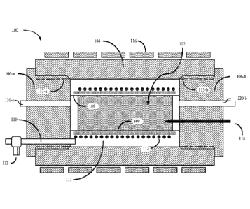
[0017] Figure lA is a schematic longitudinal sectional view of a core
holder assembly
in accordance with some embodiments.
- 4a -
Date Recue/Date Received 2021-07-15
CA 02888238 2015-04-14
WO 2014/186154
PCT/US2014/036600
100181 Figure 1B is a schematic longitudinal sectional view of a core
holder assembly
showing an exemplary flow pattern in accordance with some embodiments.
100191 Figures 2A-2C are flow charts illustrating a method of performing a
laboratory
nuclear magnetic resonance measurements of a core sample, in accordance with
some
embodiments.
100201 Figures 3A-3E are graphical representations of exemplary data
illustrating
wettability variation with temperature of a particular hydrocarbon containing
or other
formation using 2D NMR, in accordance with some embodiments.
100211 Like reference numerals refer to corresponding parts throughout the
drawings.
DESCRIPTION OF EMBODIMENTS
100221 It will be understood that, although the terms "first," "second,"
etc. are
optionally used herein to describe various elements, these elements should not
be limited by
these terms. These terms are only used to distinguish one element from
another. For example,
a first element could be termed a second element, and, similarly, a second
element could be
termed a first element, without changing the meaning of the description, so
long as all
occurrences of the "first element" are renamed consistently and all
occurrences of the second
element are renamed consistently. The first element and the second element are
both
elements, but they are not the same element.
100231 The terminology used herein is for the purpose of describing
particular
embodiments only and is not intended to be limiting of the claims. As used in
the description
of the embodiments and the appended claims, the singular forms "a", "an" and
"the" are
intended to include the plural forms as well, unless the context clearly
indicates otherwise. It
will also be understood that the term "and/or" as used herein refers to and
encompasses any
and all possible combinations of one or more of the associated listed items.
It will be further
understood that the terms "comprises" and/or "comprising," when used in this
specification,
specify the presence of stated features, integers, operations, operations,
elements, and/or
components, but do not preclude the presence or addition of one or more other
features,
integers, operations, operations, elements, components, and/or groups thereof.
100241 As used herein, the term "if" may be construed to mean "when" or
"upon" or
"in response to determining" or "in accordance with a determination" or "in
response to
detecting," that a stated condition precedent is true, depending on the
context. Similarly, the
phrase "if it is determined (that a stated condition precedent is true)" or
"if (a stated condition
precedent is true)" or "when (a stated condition precedent is true)" may be
construed to mean
- 5 -
CA 02888238 2015-04-14
WO 2014/186154
PCT/US2014/036600
"upon determining" or "in response to determining" or "in accordance with a
determination"
or "upon detecting" or "in response to detecting" that the stated condition
precedent is true,
depending on the context.
100251 As used
herein, the term "brine" may be construed to mean a fluid that
includes various salts and salt mixtures dissolved in an aqueous solution, any
saline fluid
used in completion operations or pay zone penetrating operations, and/or any
fluid used in an
enhanced oil recovery processes. In some circumstances, brines have higher
densities than
fresh water but lack solid particles that might damage producible formations.
Particular
classes of brines include chloride brines (calcium and sodium), bromides and
formates.
100261 Reference
will now be made in detail to various embodiments, examples of
which are illustrated in the accompanying drawings. In the following detailed
description,
numerous specific details are set forth in order to provide a thorough
understanding of the
present disclosure and the described embodiments herein. However, embodiments
described
herein may be practiced without these specific details. In other instances,
well-known
methods, procedures, components, and mechanical apparatus have not been
described in
detail so as not to unnecessarily obscure aspects of the embodiments.
100271 Figure 1
depicts a core holder assembly 100, in accordance with some
embodiments. During use, a core sample 102 taken from a hydrocarbon containing
formation
resides within the core holder assembly 100. In typical embodiments, core
sample 102
generally is cylindrical. However, in other embodiments core sample 102 is any
shape and
size.
100281 In some
embodiments, the core holder assembly 100 includes a pressure
chamber provided by a hull 104 and a pair of disk-shaped flanges 106-a and 106-
b that are
arranged at opposite sides of the hull 104. In some embodiments, the hull 104
is a tubular hull
(e.g., is substantially cylindrical in cross-section). In some embodiments,
the hull 104
comprises stainless steel, titanium, or some other metal, metal alloy, or
combination thereof.
In some embodiments, the disk-shaped flanges 106-a and 106-b comprise
substantially the
same material as the hull 104. In other embodiments, the disk-shaped flanges
comprise a
material distinct from the hull. In some embodiments, one of the disk-shaped
flanges 106 is
permanently affixed to the hull (e.g., by welding).
100291 The core
holder assembly 100 further includes a flexible core holder sleeve
108, which is arranged within the hull 104 and is sealingly coupled with the
disk-shaped
flanges 106. In some embodiments, the hull 104 is coupled to at least one of
the disk-shape
flanges 106-a and 106-b via threads 113-a and 113-b, respectively. In some
embodiments, the
- 6 -
CA 02888238 2015-04-14
WO 2014/186154
PCT/US2014/036600
disk-shaped flanges are sealingly coupled to the flexible core holder sleeve
108 by means of a
gasket upon which pressure is applied using threads 113-a and 113-b. In some
embodiments,
the flexible core sample holder sleeve 108 comprises a non-magnetic plastic
polymer. In
some embodiments, the non-magnetic plastic is substantially free of hydrogen.
In some
embodiments, the flexible core sample holder sleeve 108 material comprises
polytetrafluoroethylene. In some embodiments, a tubular supporter 109
surrounds the
flexible core sample holder sleeve. In some embodiments, the tubular supporter
comprises
polyether ether ketone (PEEK).
100301 The core
holder assembly 100 further includes an overburden fluid injection
port 110 fed through one of the disk-shaped flanges 106. In some
circumstances, the
overburden fluid injection port 110 is used for injecting overburden fluid
into an annular
space 111 between the hull 104 and the flexible core sample holder sleeve 108,
thereby
applying a pressure to the flexible core sample holder sleeve 108. In some
embodiments, the
tubular supporter 109 is disposed around the flexible core sample holder
sleeve 108 in such a
manner as to allow the flexible core holder sleeve 108 to remain immersed in
the overburden
fluid. In some embodiments, the flexible core sample holder sleeve 108 is
designed to
substantially transfer the applied pressure from an exterior surface of the
flexible core sample
holder sleeve 108 to an interior surface of flexible core sample holder sleeve
108, thereby
applying a pressure to a core sample residing in the flexible core sample
holder sleeve 108
during use.
100311 The core
holder assembly 100 further includes a pressure regulator 112 for
maintaining the overburden fluid in the annular space at a predetermined gauge
pressure (e.g.,
a pressure differential between the annular space and the ambient, atmospheric
pressure of
the laboratory). In some embodiments, the applied gauge pressure that the
outer sleeve is
capable of withstanding is a pressure in a range between 0 psig --10,000 psi,
0 psig --8,000
psi, 0 psig --7,500 psi, 0 psig --10,000 psi, or 0 psig to 7,500 psig.
100321 The core
holder assembly 100 further includes a radio-frequency (RF) antenna
114 within the pressure chamber. The radio-frequency (RF) antenna 114 is
wrapped around
the flexible core sample holder sleeve 108 (e.g., helically, or solenoidally).
Alternatively, in
some embodiments, the RF antenna 114 is wrapped around the tubular supporter.
The RF
antenna 114 is configured to receive an electromagnetic-signal, such as a NMR
signal, from
the core sample. In use, the core sample 102 is arranged substantially within
the sleeve. In
some embodiments, the core holder assembly 100 further includes one or more
electrical
- 7 -
CA 02888238 2015-04-14
WO 2014/186154
PCT/US2014/036600
feedthroughs configured to electrically couple a first terminal and a second
terminal of the RF
antenna to external circuitry.
100331 In some
embodiments, the core holder assembly 100 further includes one or
more heating elements 116. In some embodiments, the one or more heating
elements 116 are
disposed on an outer surface of the pressure chamber. In Figure 1, a single
heating element
116 (e.g., a resistive heating element) is shown wrapped around an outer
surface of hull (and
thus is also disposed on the outer surface of the pressure chamber). In some
embodiments,
however, one or more heating elements are incorporated into the interior of
the pressure
chamber, for example, on an inside surface of the hull. The heating element
116 is configured
to heat the overburden fluid, which acts as heat transfer medium thereby
heating the core
sample to an elevated temperature. In some embodiments, the elevated
temperature is
maintained by a temperature controller. Tn some embodiments, the heating
element 116 is
isolated from an outside environment by thermally insulating material to
prevent heat
generated by the heating element 116 from transferring to the outside
environment. In some
embodiments, the temperature controller is provided with one or more
thermocouples 118
that are, optionally, fed through one of the disk-shaped flanges 106 and
configured to be
pierced into a tail end of the core sample. In other embodiments, a sensor end
of a particular
thermocouple 118 is disposed within the annular space such that it is immersed
in overburden
fluid. A suitable calibration scheme is then used so that the temperature
regulator accurately
maintains the temperature of the core sample. In some embodiments, the heating
element is
capable of heating the core sample to an elevated temperature in the range of
about 200
degrees Fahrenheit to about 500 degrees Fahrenheit. In some embodiments, the
heating
element is capable of heating the core sample to an elevated temperature in
the range of about
room temperature to 350 degrees Fahrenheit.
100341 In some
embodiments, the core holder assembly 100 further includes a
flooding fluid injection port 120-a fed through one of the flanges of the pair
of flanges for
injecting a flooding fluid into the core sample, and a fluid outlet port fed
120-b through the
other flange for discharge of pore and/or injected fluid from the core sample.
In some
circumstances, the flooding fluid injection port 120-a and outlet port 120-b
are for use in
flooding experiments, which are described in more detail below with reference
to method 200
and Figures 2A-2C.
100351 An exemplary
fluid flow pattern (e.g., of the flooding fluid injected into the
core sample) is shown in FIG. 1B. FIG. 1B is otherwise analogous to FIG. 1A,
with the
exception that FIG. 1B includes flow lines 115 illustrating the exemplary flow
pattern
- 8 -
CA 02888238 2015-04-14
WO 2014/186154
PCT/US2014/036600
between fluid injection port 120-a and outlet port120-b. In some
circumstances, the flow
pattern is non-uniform, depending upon the specifics of injection of the fluid
through fluid
injection port 120-a, outlet through outlet port 120-b, the nature of the rock
(e.g., spatial
variations in permeability, etc). In some embodiments, a flow rate of the flow
pattern is
approximately constant. Alternatively, various flow rates are used. In some
embodiments, an
alternating flow gradient is employed during flooding. It should be understood
that the range
of flow range can be wide as long as the pressure caused by the flooding
process is within the
designed pressure limit of the core holder assembly 100.
100361 Accordingly,
the core holder assembly 100 allows flooding experiments to be
performed under realistic high-pressure, high temperature (HPHT) well (e.g.,
logging)
conditions while using the RF antenna 114 to measure NMR signals.
100371 The core
holder assembly 100 may be used for static or core flooding
experiments for the experimental study of process parameters for enhanced oil
recovery
(EOR) processes, described with reference to method 200 and Figures 2A-2C,
below. For
example, these process parameters may play a role during steam injection
processes for
thermal EOR of heavy oil (HVO) fields. In such a circumstance, one objective
is to shed light
on the fundamentals of heat transfer and oil mobilization prevailing during
steam flooding
and cyclic steam stimulation, and to optimize the process parameters for EOR.
100381 Accordingly,
Figures 2A-2C are flowcharts illustrating a method 200 of
performing laboratory nuclear magnetic resonance measurements of a core
sample, in
accordance with some embodiments using core holder assembly 100.
100391 The method
200 includes saturating (202) a core sample with one or more
fluids. The one or more fluids include at least one of a hydrocarbon-based
fluid (e.g., oil) and
a brine. For example, when the core sample is positioned within the flexible
core sample
holder sleeve 108 (Figure 1), the one or more fluids can be pumped into
flooding fluid
injection port 120-a at a suitable pressure and for a suitable duration of
time to saturate the
core sample with the one or more fluids.
100401 The method
200 further includes, while the core sample is (204) saturated with
the one or more fluids, applying (206) a first pressure to an exterior surface
of a core sample.
In some embodiments, applying the first pressure to the sleeve includes
positioning (208) the
core sample substantially within a sleeve (e.g., the flexible core sample
holder sleeve 108,
Figure 1). The sleeve comprises a respective material and is capable of
transmitting, from an
exterior surface of the sleeve to an interior surface of the sleeve, an
applied pressure. Thus,
when a pressure is applied to the exterior surface of the sleeve, the pressure
is substantially
- 9 -
CA 02888238 2015-04-14
WO 2014/186154
PCT/US2014/036600
transmitted to the core sample substantially within the sleeve. In some
embodiments, the
respective material is (210) substantially free of hydrogen. Using a material
that is
substantially free of hydrogen for the sleeve allows for the use of hydrogen-
based NMR
experiments, which would otherwise be hindered by a detrimental hydrogen NMR
signal of
the sleeve. In some embodiments, the respective material comprises
polytetrafluoroethylene
(212), which is known by the trade name TEFLON , produced the DuPont
Corporation.
Polytetrafluoroethylene is capable of withstanding a variety of temperatures
and pressures of
interest when performing laboratory NMR experiments of core samples under
conditions
representative of in-situ conditions.
100411 In some
embodiments, applying the first pressure further includes surrounding
(214) the sleeve with an overburden fluid (e.g., by injecting the overburden
fluid into the
annular space via overburden fluid injection port 110, Figure 1). In some
embodiments, the
overburden fluid is substantially free of hydrogen. In some embodiments, the
overburden
fluid is electrically insulating. In some embodiments, the overburden fluid
comprises a
fluorocarbon-based fluid. In some embodiments, the overburden fluid comprises
a fluid
having a chemical formula CõFy, where x and y are the same or different
positive integers. In
some embodiments, the overburden fluid comprises one or more FLUORINERTTm
fluids
(e.g., FC-70, FC-75) produced by the 3M Corporation.
100421 In some
embodiments, applying the first pressure further includes pressurizing
(216) the overburden fluid (e.g., using pressure regulator 112, Figure 1),
thereby applying a
pressure to the exterior surface of the sleeve. In some embodiments, the first
applied pressure
is (218) in a range between 0 psig to 7,500 psig.
100431 The method
200 further includes, while the core sample is saturated with the
one or more fluids, heating (220) the core sample to a first elevated
temperature. In some
embodiments, heating the core sample includes heating (222) the overburden
fluid, thereby
indirectly heating the core sample by using the overburden fluid as a heat-
transfer medium.
For example, a heating element (e.g., heating element 116, Figure 1) can be
disposed inside
or outside of a pressure chamber containing the overburden fluid. Heat from
the heating
element is transferred to the overburden fluid, and subsequently to the core
sample. In some
embodiments, the first elevated temperature is (224) in a temperature range of
about 200
degrees Fahrenheit to about 500 degrees Fahrenheit. In some embodiments, the
temperature
is monitored by a thermocouple disposed either in the core sample, on the
exterior surface of
pressure chamber or in the overburden fluid, as described with reference to
Figure 1.
- 10 -
CA 02888238 2015-04-14
WO 2014/186154
PCT/US2014/036600
100441 The method
200 further includes, while the core sample is saturated with the
one or more fluids, generating (226) NMR data of the core sample and the one
or more fluids
at the first applied pressure and first elevated temperature (e.g., using RF
antenna 114 to
receive an NMR signal from the core sample). In some embodiments, the NMR data
is low-
field NMR data taken while the core sample is subject to a uniform low
magnetic field (e.g.,
in the range of mT, 1iT, or nT). In some embodiments, the low magnetic field
is the Earth's
magnetic field.
100451 The method
200 further includes determining (228) a value of one or more
physical characteristics of the core sample and the one or more fluids as a
function of the first
applied pressure and the first elevated temperature. In some embodiments,
determining the
value of the one or more physical characteristics of includes performing (230)
at least one of:
typing hydrocarbons in the one or more fluids, estimating pore-size
distributions of the core
sample, evaluating a viscosity of the one or more fluids, determining a
permeability of the
core sample, and determining a vvettability of the core sample. It is
envisioned that the
operation of determining the one or more physical characteristics could take
place in real-
time (e.g., while the core sample is saturated with the one or more fluids),
or during off-line
analysis, or a combination thereof.
100461 In some
embodiments, the method 200 further includes determining (232) the
at least one characteristic of the core sample under static conditions and
further determining
the at least one characteristic under flooding conditions. In some
embodiments, determining
the at least one characteristic under flooding conditions includes, while
performing the
generating operation, pumping (234) at least one flooding fluid into the core
sample. In some
embodiments, the at least one flooding fluid is pumped into the core sample at
a substantially
constant rate. In some embodiments, the at least one flooding fluid includes
oil, water, brine,
or a mixture thereof. In some embodiments, the at least one flooding fluid
includes a gas. In
some embodiments, the gas includes carbon dioxide, nitrogen, methane, sulfur
dioxide,
nitrogen dioxide, or a mixture thereof
100471 In some
embodiments, the method 200 further includes, while the core sample
is saturated with the one or more fluids, applying (236) a second pressure,
distinct from the
first applied pressure, to the exterior surface of a core sample, heating
(238) the core sample
to a second elevated temperature distinct from the first elevated temperature,
and generating
(240) NMR data of the core sample and the one or more fluids at the second
applied pressure
and second elevated temperature.
- 11 -
CA 02888238 2015-04-14
WO 2014/186154
PCT/US2014/036600
100481 In some
embodiments, the method 200 further includes determining (242) a
second value for the one or more physical characteristics of the core sample
and the one or
more fluids as a function of the second applied pressure and second elevated
temperature. It
is further envisioned that the first and second values could each be
determined under each of
static and flooding conditionings using the procedure described above.
100491 In some
embodiments, the method 200 further includes optimizing (244) an
enhanced oil recovery process using at least the first and seconds values
(e.g., under static
conditions, flooding conditions, or a combination thereof) of the one or more
physical
characteristics.
100501 Figures 3A-
3E are graphical representations of exemplary data illustrating
wettability variation with temperature of a particular hydrocarbon containing
or other
formation using 2D NMR, in accordance with some embodiments. Data presented in
Figures
3A-3E are obtained, for example, by practicing aspects of method 200 described
with
reference to Figure 2A-2C.
100511 Figure 3A
includes plot 300, which is a 2D NMR contour plot illustrating
NMR signal strength (represented by contours) versus a T2 relaxation time in
milliseconds
(labeled "Relaxation Time (ms)") along the horizontal axis and a diffusion
coefficient in
micrometers per millisecond along the vertical axis. Plot 300 corresponds to a
respective
hydrocarbon containing or other formation (e.g., data is obtained using a core-
sample taken
therefrom) at a pressure of about 2,000 psig and a temperature of 77 degrees
Fahrenheit.
Figure 3A also includes plot 302, which is a one-dimensional plot of NMR
signal strength
versus diffusion coefficient (i.e., averaged over the T2 relaxation time) and
plot 304, which is
a one-dimensional plot of NMR signal strength versus T2 relaxation time (i.e.,
averaged over
the diffusion coefficient). Plot 300 shows a peak in the NMR signal due water
at a location
designated by 306-a, indicating an apparent 7'2 relaxation time of water
(T73,w).
100521 Figure 3B is
analogous to Figure 3A with the difference being that data shown
in Figure 3B is taken at a pressure of about 2,000 psig and an elevated
temperature of 175
degrees Fahrenheit. Plot 300-b again shows the water peak in the NMR signal,
however, in
plot 300-b, the location of the water peak has moved slightly to the right
along the horizontal
axis to a location designated by 306-b. The movement of the location of the
water peak to
the right in plot 300 signifies a water wet condition of the core-sample's
water peak, which
represents a condition of the core-sample in which a thin film of water coats
a surface of a
matrix of the core-sample and thus the formation rock preferentially imbibes
water. Such a
-12-
CA 02888238 2015-04-14
WO 2014/186154
PCT/US2014/036600
water wet condition is desirable for efficient oil transport and is thus
desirable for enhanced
oil recovery.
100531 Figure 3C is
analogous to Figure 3B with the difference that data shown in
Figure 3C is taken at a pressure of about 2,000 psig and an elevated
temperature of 212
degrees Fahrenheit. Plot 300-c again shows the water peak in the NMR signal,
however, in
plot 300-c, the location of the water peak has moved further to the right of
306-b along the
horizontal axis to a location designated by 306-c. As described below, in this
exemplary
data, temperatures higher than 212 degrees cause the water peak to transition
to an oil wet
condition (e.g., the water peak is characterized by a "kink-point" at 212
degrees), which is
not desirable for enhanced oil recovery. An optimum (e.g., highest) diffusion
coefficient
under water wet conditions is also observed when the temperature is 212
degrees.
100541 Figure 3D is
analogous to Figure 3C with the difference being that data shown
in Figure 3D is taken at a pressure of about 2,000 psig and an elevated
temperature of 248
degrees Fahrenheit. Plot 300-d again shows the water peak in the NMR signal,
however, in
plot 300-d, the location of the water peak has moved to the left of 306-c
along the horizontal
axis to a location designated by 306-d. The movement of the location of the
water peak to
the left in plot 300-d signifies an oil wet condition of the core-sample's
water peak, which
represents a condition of the core-sample in which a thin film of oil coats
the surface matrix
of the core-sample and thus the formation rock preferentially imbibes oil.
Such an oil wet
condition is detrimental for efficient oil transport and recovery and is thus
not desirable for
enhanced oil recovery.
100551 Figure 3E is
analogous to Figure 3D with the difference being that data shown
in Figure 3E is taken at a pressure of about 2,000 psig and an elevated
temperature of 284
degrees Fahrenheit. Plot 300-e again shows the water peak in the NMR signal,
however, in
plot 300-e, the location of the water peak has moved further to the left of
306-d along the
horizontal axis to a location designated by 306-d, signifying that the water
peak remains in
the oil wet condition.
100561 In some
embodiments, the peak locations 306 are used to generate a forward
model of one or more wettability indices of the core sample (e.g., a water
index and an oil
index), as described below. In some embodiments, because the core sample is
taken from a
respective hydrocarbon or other containing formation, the forward model for
the one or more
indices of the core sample is also a forward model for the one or more indices
of the
respective hydrocarbon or other containing formation.
-13-
[0057] The apparent T2 relaxation time of water (T2) at a given
temperature is related to
the water wettability index via the equation:
1 1
+ iwA +1 1 1 , (1)
T2b,vv 2Sw 2a,w,(s.õ,-1) T2b,w
where T2b,w is a bulk T2 relaxation time of water, LA is a water wettability
index (e.g., an Amott
water wettability index), Sw is a water saturation of pore spaces within the
core sample (typically
obtained through separate testing of a core sample from the same hydrocarbon
or other containing
formation), and T2a,.,(sw=i) is an apparent T2 relaxation time of water at
Sw=1 when the pores spaces
are strong water wet.
[0058] In general, T2a,w, T2b,w and LA are each a function of
temperature. Thus, Eq. (1) is
an implicit function of temperature. In some embodiments, the apparent T2
relaxation time of
water (T2) is measured at a variety of temperatures in a manner consistent
with the method 200
and FIGS. 3A-3D, as described above, thereby providing an empirical
relationship for T2 to to use
in conjunction with Eq. (1). In some embodiments, a relationship for a T1
value of bulk water
(Tib,w ) as a function of temperature is obtained by fitting empirical data
with a function of the
form:
Tib,w = Al3 +B12 D (2)
where t is the temperature of the bulk water. Such empirical data is provided,
for example, in
"Kleinberg, R.L., Vinegar, H.J., (1996) NMR properties of reservoir fluids.
The Log Analyst
37(6), page 20-32." A constant ratio of T11,,w IT2,,w (e.g., constant as a
function of temperature) is
used to convert the 7'1 values obtained from Eq. (2) into T2 values. In some
embodiments, the
constant ratio is a fitting parameter. In some embodiments, the constant ratio
is 2.5. Substituting
the T2 obtained obtained in this manner from Eq. (2) into Eq. (1), while using
experimental data for Sw,
and using the emperical relationship for T2,' as a function of temperature
yields an empirical
relationship for LA as a function of temperature. The empirical relationship
is then converted to a
forward model by fitting the empirical data to the equation:
(3)
wA = b ¨ b2 + b2
1 (1 1 OP
where b1 = 0, b2 = 1, and tc and 16 are fitting parameters for the forward
model.
[0059] The foregoing description, for purpose of explanation, has been
described with
reference to specific embodiments. However, the illustrative discussions above
are not
- 14 -
Date Re9ue/Date Received 2020-09-25
CA 02888238 2015-04-14
WO 2014/186154
PCT/US2014/036600
intended to be exhaustive or to limit the embodiments to the precise forms
disclosed. Many
modifications and variations are possible in view of the above teachings. The
embodiments
were chosen and described in order to best explain the principles of the
disclosure and its
practical applications, to thereby enable others skilled in the art to best
utilize the various
embodiments with various modifications as are suited to the particular use
contemplated.
-15-