Note: Descriptions are shown in the official language in which they were submitted.
264692
LED LAMP WITH ND-GLASS BULB
FIELD OF THE INVENTION
[0002] Embodiments of the present invention generally relate to lighting and
lighting
devices. In particular, the present disclosure relates to embodiments of a
lighting apparatus
using light-emitting diodes (LEDs), wherein the embodiments exhibit a spectral
power
distribution with enhanced red-green color contrast and enhanced overall color
preference. In
certain embodiments, lamps described herein may pertain to A-line lamps (e.g.,
A19-type) or BR
lamps (e.g., BR30-type).
BACKGROUND OF THE INVENTION
[0003] Incandescent lamps (e.g., integral incandescent lamps and halogen
lamps) mate
with a lamp socket via a threaded base connector (sometimes referred to as an
"Edison base" in
the context of an incandescent light bulb). These lamps are often in the form
of a unitary
package, which includes components to operate from standard electrical power
(e.g., 110 V
and/or 220 V AC and/or 12 VDC). Such lamps find diverse applications such as
in desk lamps,
table lamps, decorative lamps, chandeliers, ceiling fixtures, and other
general illumination
applications. Several geometric shapes of incandescent lamps are used in such
applications,
including, but not limited to, A-line, R, BR, PAR, Decorative (Deco), and MR
types of lamps.
[0004] Some types of incandescent lamps have an enhanced ability to render the
red-
green color contrast of illuminated objects. Such lamps have great appeal to
users of lamps to
illuminate objects, since they may cause the color of such objects to appear
more rich or
saturated. Especially appealing incandescent lamps of this type include the
Reveal brand of
1
CA 2888268 2018-02-23
CA 02888268 2015-04-16
WO 2014/063011 PCT/US2013/065609
lamps which are sold by GE Lighting, an operating division of the General
Electric Company.
Customers of Reveal products also prefer the "whiter" and "brighter"
appearance of the light,
and the enhanced overall color preference when compared to an unenhanced white
spectrum.
[0005] Solid-state lighting technologies such as light-emitting diodes (LEDs)
and LED-
based devices often have superior performance when compared to incandescent
lamps. This
performance can be quantified by the useful lifetime of the lamp (e.g., its
lumen maintenance and
its reliability over time), lamp efficacy (lumens per watt), and other
parameters.
[0006] It may be desirable to make and use an LED lighting apparatus also
having
appealing red-green color contrast properties.
SUMMARY OF THE INVENTION
[0007] Presented herein are LED based lamps. In an advantageous embodiment, an
LED based lamp includes a concave optical diffuser, a separate concave
neodymium-doped glass
bulb, a reflector, a printed circuit board that includes a plurality of light-
emitting diodes (LEDs)
configured to emit light, and a heat sink body. The concave optical diffuser
has a first interior
volume, and the concave neodymium-doped glass bulb is positioned within the
first interior
volume. The neodymium-doped glass bulb defines a second interior volume, and
both the
reflector and the printed circuit board are positioned within the second
interior volume. In some
embodiments, the reflector includes a sloped annular wall with an inner
reflective surface and an
outer reflective surface, and a bottom portion of the reflector is connected
to the printed circuit
board. The heat sink is thermally connected to the printed circuit board and
to the reflector.
[0008] In other beneficial embodiments, an LED based lamp is configured as a
flood
lamp, or BR-type lamp. In an implementation, an LED lamp includes an optical
diffuser having
a disc or concave disc shape, a heat sink body affixed to the optical
diffuser, a reflector, a
concave neodymium-doped glass bulb, and a printed circuit board comprising a
plurality of
LEDs. The heat sink body has a wall defining a first interior volume, and the
reflector has a
sloped annular reflective wall and is positioned within the first interior
volume. The heat sink
body has an interior surface defining a second interior volume, and the
concave neodymium-
doped glass bulb is positioned within the second interior volume. The printed
circuit board is
2
CA 02888268 2015-04-16
WO 2014/063011 PCT/US2013/065609
positioned at a lower portion of the reflector and is in thermal communication
with the heat sink
body. The plurality of LEDs on the printed circuit board is configured to emit
light through the
concave neodymium-doped glass bulb.
BRIEF DESCRIPTION OF THE DRAWINGS
[0009] Aspects and/or features of the invention and many of their attendant
benefits
and/or advantages will become more readily apparent and appreciated by
reference to the
detailed description when taken in conjunction with the accompanying drawings,
which
drawings may not be drawn to scale.
[0010] FIG. 1 is a schematic side-view depiction of exemplary lighting
apparatus or
lamp of the A-line type according to an embodiment of the invention;
[0011] FIG. 2 is an exploded schematic perspective view of an exemplary
lighting
apparatus or lamp of the A-line type according to an embodiment of the
invention;
[0012] FIG. 3 illustrates an embodiment of a flood lamp incorporating
components in
accordance with an embodiment of the invention;
[0013] FIG. 4 is a cross-sectional view of the flood lamp of FIG. 3 in
accordance with
embodiments of the invention;
[0014] FIG. 5 is an exploded perspective view of the flood lamp of FIG. 4 in
accordance
with embodiments of the invention;
[0015] FIGS. 6 and 7A illustrate side and perspective side views,
respectively, of a light
source having a toroidal diffuser in accordance with embodiments of the
invention; and
[0016] FIG. 7B depicts a variant embodiment of the light source of FIG. 7A in
accordance with embodiments of the invention.
DETAILED DESCRIPTION
[0017] In general, and for the purpose of introducing concepts of embodiments,
described are LED-based lighting apparatus or lamps.
3
CA 02888268 2015-04-16
WO 2014/063011 PCT/US2013/065609
[0018] In some embodiments (for example, an A-line), the apparatus comprises
an
optical diffuser having a hemispheroidal, spheroidal, prolate or oblate
ellipsoidal, ovoid, conical,
polygonal-faced, or toroidal shape. The diffuser has a concave side defining a
first interior
volume. The apparatus further comprises a glass bulb having a hemispheroidal,
spheroidal,
prolate or oblate ellipsoidal, ovoid, conical, polygonal-faced, or toroidal
shape, not necessarily
the same shape as the optical diffuser, and doped with neodymium (Nd) oxide,
Nd203,
substantially nested within the first interior volume and generally separate
from the optical
diffuser. The bulb has a concave side which further defines a second interior
volume. The
apparatus includes a reflector, such as a truncated tapered reflector, i.e.,
generally having a shape
of a truncated axisymmetric revolution of a conic section, and having an
internal and external
surface. In an implementation, the reflector has a sloped annular wall
generally having a cross-
section shape of a conic section. However, in some embodiments the sloped
annular wall may
be a straight wall or may be a curved wall. In some embodiments, the reflector
also comprises a
central transparent portion or central aperture defined by the interior of the
reflector wall. The
reflector is received substantially within the second interior volume.
[0019] In some embodiments, the lamp further comprises a plurality of LEDs
mounted
to a circuit board. The plurality of LEDs is configured to emit light
generally axially upward, in a
direction substantially perpendicular to the circuit board. Note that the
apparatus is generally
longitudinal, with a diffuser at an upper end and a base at a lower end. At
least a first portion of
the plurality of LEDs is configured to emit light through a central aperture
of the reflector. In
addition, at least a second portion of the plurality of LEDs is configured to
emit light that reflects
from a sloped annular reflective wall of the reflector.
[0020] The apparatus may further include a heat sink body which is in thermal
communication with the circuit board, in order to dissipate the heat emanating
from the plurality
of LEDs when the apparatus is in operation. In the A-line embodiment, the heat
sink body may
include an annular groove at an upper portion thereof. The annular groove is
sized and shaped to
receive both a lip of the bulb and a lip of the diffuser therein.
[0021] The apparatus may further include a capper that has driver circuitry
substantially
enclosed within. The capper may be affixed to a lower portion of the heat
sink. In some
implementations, the apparatus includes a threaded base, to receive power from
a socket.
4
264692
[0022] In an A-line embodiment, the optical diffuser may be made of a glass or
a
polymeric material, e.g., a polycarbonate such as Teijin ML5206. The optical
diffuser is usually
capable of veiling light, such that light from individual LEDs is mixed and/or
obscured.
Generally, the diffuser distributes light and diffuses the light of individual
LEDs. The optical
diffuser may comprise a weakly diffusing low-optical-loss injection molded
plastic bulk diffuser.
In some embodiments, the optical diffuser generally has a white external
appearance when the
apparatus is not in operation. The optical diffuser is generally separate from
the neodymium-
doped glass bulb and functions to diffuse light from the LEDs and to
advantageously protect the
neodymium-doped glass bulb from shattering or cracking from potentially
damaging impacts that
may occur (such as when or if the lamp is dropped onto a floor having a hard
surface).
[0023] The glass bulbs in accordance with the embodiments disclosed herein may
comprise a nominally soda lime glass, having impregnation with a neodymium
compound such
as neodymium oxide. The glass may comprise from about 2 wt% to about 15 wt%
Nd203, for
example, 6 wt% Nd203. It is not preferred for the Nd203 to be impregnated into
some polymer
materials, in which the peak wavelength of the absorption may be shifted from
that of the Nd-
glass absorption which typically peaks at about 585 nm as shown in U.S.
Published Patent
Application No. 2007/0241657 Al. The peak wavelength and shape of the
absorption spectrum
depends on the material matrix into which the Nd203 is embedded, such that in
some polymer
embodiments, the peak absorption is so far away from the desired 585 nm, that
the desired red-
green enhancement is not obtained, or is not optimized. The glass bulb may
also have an outer
diameter of from about 50 to about 60 millimeters (mm) (for example, about 52
mm) and a wall
thickness of from about 0.1 to about 2 mm (e.g., 0.5 mm). One function of the
glass bulb is to
absorb light from the LEDs when the apparatus is in operation, to induce a
depression in a yellow
portion of the visible light spectrum when light is transmitted therethrough.
Of course, other
types of glass or glass bulbs are possible, provided that such glass bulbs can
modify a light source
to induce a depression in a yellow portion of the visible light spectrum and
increase red-green
color contrast. In addition, other dimensions of the glass bulb are possible,
as long as the glass
bulb is in the optical path of some or all of the light emitted by the LEDs.
CA 2888268 2018-09-20
CA 02888268 2015-04-16
WO 2014/063011 PCT/US2013/065609
[0024] As aforementioned, in the A-line embodiment, the truncated conical
reflector has
a central aperture, and a first portion of the plurality of LEDs is configured
to emit light rays
axially through the central aperture. These light rays impinge directly onto
the glass bulb and
pass through to impinge on the optical diffuser. There is also a second
portion of the plurality of
LEDs which is arranged or configured to emit light so as to reflect from an
external surface of
the reflector, so as to distribute light in a radial direction and also in the
direction of the base at
the lower end of the apparatus. This combination of reflector and diffuser is
effective to
distribute light in a nearly omnidirectional manner. Generally, the reflector
comprises a wider
end and a narrow end, with the narrow end proximate the circuit board and with
the wider end
proximate the neodymium-doped glass bulb. A reflector in accordance with the
several
embodiments described herein may comprise a polymeric material and may be
injection molded,
although it may also be formed of metallic material in part or in whole. The
external surface of
the reflector may be a specular or a diffuse white, high reflectivity surface.
Such a high
reflectivity surface is usually achieved via highly reflective coatings and/or
laminates.
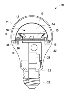
[0025] FIG. 1 is a schematic side-view depiction of exemplary lighting
apparatus or
lamp 10 of the A-line type according to an embodiment. The lamp 10 includes an
optical
diffuser 11 defining a first interior space 12. Nested within interior space
12 is Nd-glass bulb 13,
which defines a second interior space 14. A reflector 15 sits substantially
within the second
interior space 14. The reflector 15 comprises a central aperture 16 and a
sloped side wall 17.
Immediately below the reflector is the plurality of LEDs (not shown in this
view) which may be
mounted on a printed circuit board, such as a metal-core printed circuit board
(MCPCB, not
shown). In some embodiments, the reflector and/or circuit board are thermally
connected to a
heat sink body 20 by screws 18, while in other implementations the reflector
and printed circuit
board are otherwise affixed to the heat sink body, for example by a thermally
conducting epoxy.
An annular groove 19 is located on an upper portion of the heat sink body 20,
and is sized and
shaped to receive a diffuser lip 25 and a glass bulb lip 26. Cement or
adhesive (not shown) may
be used to affix the optical diffuser 11 and the glass bulb 13 to the annular
groove 19. A capper
22 is shown that contains the driver electronics/circuitry 21. The lighting
apparatus 10 is
completed at its lower portion with a screw-threaded base 23. It should be
understood that the
lighting apparatus 10 also includes suitable wiring and additional components
(not shown) to
6
CA 02888268 2015-04-16
WO 2014/063011 PCT/US2013/065609
receive current at the driver circuitry 21 and to transmit a suitable current
and voltage to drive
the plurality of LEDs.
[0026] FIG. 2 is an exploded schematic perspective view of an exemplary
lighting
apparatus or lamp 100 of the A-line type. The lamp 100 includes an optical
diffuser 101 having
a lip 102, and glass bulb 103 having a lip 104, both of which configured for
seating in the
annular groove 114 formed in an upper portion of the heat sink body 113. The
apparatus 100 also
includes a reflector 106 which has a bottom portion that is configured for
attachment to the
circuit board 110 and heat sink body 113 by screws 105. The central aperture
108 of the
reflector 106, and the sloped wall 107 of the reflector 106, are also shown in
this perspective
view. The circuit board 110, which may be generally circle-shaped, includes a
central array of
LEDs 111 consisting of a plurality of LEDs located about a central portion
thereof, and includes
an annular array of LEDs 112 including a plurality of LEDs arrayed about an
outside portion
thereof. The combination of the central array of LEDs 111 and the annular
array of LEDs 112
forms a light engine 109. The light engine 109 is configured for mounting in
thermal
communication with the heat sink body 113. Located at a lower portion of the
lamp 100 is the
capper 116, which is configured for housing the driver electronics 115 and for
attachment to the
base 117.
[0027] FIG. 3 illustrates a flood lamp 300 that incorporates the components
described
herein in accordance another embodiment, known as a BR-type lamp. Lamps with
such a shape
and form factor have generally been categorized by the American National
Standards Institute
(ANSI) as having part numbers BR20, BR30, BR40, and the like, with the
difference between
the various lamps being their largest diameter, expressed in one-eights
(1/8's) of an inch, so that,
for example the BR20 lamp has a diameter of 20/8". These flood-lamp type lamps
typically
have a form factor incorporating a slight bulge in their base section and have
been designated by
ANSI with a "B" prefix to highlight this feature.
[0028] FIG. 4 is a cross-sectional view 400 of a BR30 type lamp, and FIG. 5 is
an
exploded perspective view 500 of the same BR30 type lamp, in accordance with
some
embodiments. The apparatus 400, 500 includes an optical diffuser 404, 504
having a convex
meniscus or a disc shape having a curved edge. The diffuser 404, 504 thus has
a concave side or
flat inner side adjoining a first interior volume. In some embodiments, the
optical diffuser may
7
CA 02888268 2015-04-16
WO 2014/063011 PCT/US2013/065609
include a glass material, or a polymeric material, including many of the
materials suitable for the
optical diffuser discussed above with regard to the A-line embodiment. As
above, the optical
diffuser is capable of veiling light, such that light from individual LEDs is
mixed and/or
obscured. Note that the optical diffuser generally may have a white external
appearance when
the apparatus is not operation.
[0029] In some embodiments, a heat sink body 406, 506 may be mated or
otherwise
affixed to the optical diffuser 404, 504. As shown in FIGS. 4 and 5, the
curved edge portion of
the disc-shaped diffuser 404, 504 is configured to mate with an upper edge
portion of the heat
sink body 406, 506. An interior of the heat sink body 406, 506 defines a first
interior volume.
The heat sink body may be in thermal communication with a circuit board 401,
501 (described in
more detail below), in order to dissipate heat emanating from a plurality of
LEDs mounted
thereon when the apparatus is in operation. A reflector 403, 503, having a
shape that may be
generally described by an axisymmetric revolution of a conic section
(described more fully
below) may be annularly received in the first interior volume. The heat sink
body 406, 506 may
be sized and shaped to receive and retain the reflector 403, 503 in its
interior, as well as to impart
the general BR-type appearance at its exterior.
[0030] In this example embodiment, the LED lamp 400, 500 may include a
truncated
reflector 403, 503 having a sloped annular reflective wall generally described
by an
axisymmetric revolution of a conic section, and a central aperture. The
truncated reflector may
generally have a shape of a truncated cone or parabola, or possibly a compound
parabolic
collector (CPC). This reflector may be received substantially within the first
interior volume
defined by the heat sink body 406, 506. An interior of the truncated reflector
403, 503 defines a
second interior volume. The truncated reflector 403, 503 also may include a
central transparent
portion or central aperture on a forward end or top end thereof, to permit
light emitted from a
light engine (or light module including a plurality of LEDs) to impinge upon a
Nd-doped glass
dome 402, 502. The central aperture may be defined by the interior wall of the
truncated
reflector. In some embodiments, a reflector in accordance of this disclosure
may be of a
polymeric material and may be injection molded, but it could also be formed of
a metallic
material in part or in whole. In some implementations, the internal surface of
the reflector 403,
8
264692
503 comprises a diffusive high reflectivity surface. This diffusive high
reflectivity surface may
be achieved via highly reflective paints and/or laminates.
[0031] The LED based lighting apparatus 400, 500 may include a hemi-spheroidal-
shaped neodymium-doped glass bulb 402, 502 nested substantially within the
second interior
volume defined by the truncated reflector 403, 503. In some embodiments, a
ring (not shown)
that surrounds the Nd-doped glass dome is utilized to affix the dome to the
inside surface of the
truncated diffuser.
[0032] As noted above, glass bulbs in accordance with some embodiments of this
disclosure may include a nominally soda lime glass, having impregnation with a
neodymium
compound such as neodymium oxide. The same or similar proportions of Nd
described
hereinabove may be provided. Such glass bulbs may have a wall thickness of
from about 0.1
mm to about 1 mm (for example, 0.5 mm). One function of the Nd-doped glass
bulb is to absorb
light from the LEDs when the apparatus is in operation, to induce a depression
in a yellow
portion of the visible light spectrum when light is transmitted therethrough,
which provides
enhanced red-green color contrast of illuminated objects as compared to
conventional LED
lamps. Such lamps thus hold great appeal to users for illuminating objects to
cause the color of
those objects to appear more rich or saturated. Descriptions of how Nd-doped
glass bulbs may
provide enhanced red-green color contrast can be found in U.S. Published
Patent Application
No. 2007/0241657.
[0033] Of course, other types of glass or glass bulbs are possible, provided
they can
modify a light source to induce a depression in a yellow portion of the
visible light spectrum and
increase red-green color contrast.
[0034] Referring again to FIGS. 4 and 5, the lamp 400, 500 of the BR
embodiment may
include a plurality of LEDs mounted to a circuit board 401, 501. The circuit
board is usually
located at a position proximate (or at) a lower portion of the truncated
reflector 403, 503, and is
in thermal communication with the heat sink body 406, 506. The plurality of
LEDs may be
configured to emit light generally axially, with at least a portion of the
plurality of LEDs
configured to emit light through the central aperture and thereon through the
spheroidal
neodymium-doped glass bulb 402, 502. The plurality of LEDs may also be
configured to emit
light that reflects from the sloped annular reflective wall of the truncated
reflector 403, 503. In
9
CA 2888268 2018-02-23
CA 02888268 2015-04-16
WO 2014/063011 PCT/US2013/065609
some embodiments, the plurality of LEDs is mounted to a circuit board in a
substantially planar
configuration, the circuit board may be connected to the heat sink body 506
and capper 508 via
screws 505, and the circuit board may have a circular cross section. For
example, in the BR30
embodiment, the plurality of LEDs may include 20 LEDs, wherein most or all of
the LEDs
reside in a central region of the circuit board. It should be understood,
however, that other
numbers and arrangements of LEDs are possible.
[0035] In the apparatus of the BR embodiment of FIGS. 4 and 5, a capper 408,
508 is
configured to enclose driver circuitry and may be affixed to a lower portion
of the heat sink body
406, 506. The capper 408, 508 encloses a drive board or driver electronics
407, 507 in its
interior. The capper 408, 508 is affixed to a lower portion of the heat sink,
and is also connected
to a threaded base 409, 509, to receive power from an electrical socket.
[0036] The circuit board 401, 501 may be affixed to the heat sink body 406,
506 by a
mechanical connection and/or by an adhesive, for example, by a thermally
conductive adhesive.
In some embodiments, the circuit board may comprise a substantially planar
metal-core printed
circuit board (MCPCB).
[0037] In some embodiments, the capper is sized and shaped to accept the
driver
circuitry or electronics for the lamp, while still permitting the apparatus to
attain the aspect or
profile conforming to the ANSI A19 or BR30 profile. Typically, the capper
comprises a
polymer, such as a thermoplastic engineering polymer, for example, PBT. Some
embodiments
utilize a base (23, 117, 409, 509), which may be a threaded Edison base. The
lighting apparatus
may be characterized as being configured with components that mate with a lamp
socket via a
threaded Edison base connector. The lighting apparatus may be further
characterized as being an
integral lamp constructed as a unitary package including all components
required to operate from
standard electrical power received at the base thereof
[0038] FIGS. 6 and 7A diagrammatically illustrate side 600 and perspective
side views
700, respectively, of a light source employing principles disclosed herein
with a toroidal diffuser.
FIG. 7B depicts a variant embodiment 750.
[0039] With reference to FIGS. 6 and 7A, yet another embodiment is disclosed.
This
embodiment is an LED lamp suitable for replacing an incandescent light bulb
and including the
Edison base connector 30 facilitating use of the lamp as a retrofit
incandescent bulb. A ring
264692
shaped LED-based light source 150 is arranged on a cylindrical former or
chimney 152 so as to
emit light outward from the cylindrical former or chimney 152. A toroidal
diffuser 156 having a
circular cross section (best seen in FIG. 6) is arranged to receive and
scatter most of the
illumination intensity 154. (Note that in FIGURE 7A the toroidal diffuser 156
is
diagrammatically shown in phantom in order to reveal LED based light source
150). A toroidal
Nd glass filter 158 having a circular cross section is arranged to receive and
filter most of the
illumination intensity 154. However, the Nd glass filter 158 may be of another
shape or
geometry instead of toroidal in some embodiments.
[0040] The ring-shaped LED-based light source 150 is arranged tangential to
the inside
vertical surface of the toroidal diffuser 156 and emits its Lambertian
illumination intensity 154
into the toroidal diffuser 156. The toroidal diffuser 156 preferably has a
Lambertian-diffusing
surface as diagrammatically illustrated in FIG. 6, so that at each point on
the surface the incident
illumination 154 is diffused to produce a Lambertian intensity output pattern
emanating
externally from that point on the surface of the toroidal diffuser 156. As a
consequence, the
lighting assembly comprising the ring-shaped LED-based light source 150 and
the toroidal
diffuser 156 of circular path cross-section generates light that is
substantially omnidirectional
both latitudinally and longitudinally.
[0041] The illustrated ring-shaped LED-based light source 150 is arranged
tangential to
the inside surface of the toroidal diffuser so that the illumination intensity
pattern 154 is emitted
most strongly in the horizontal, radial direction. In other embodiments, the
ring-shaped
LED-based light source 150 is arranged tangential to the bottom or top inside
surface of the
toroidal diffuser 156, or at any intermediate angular position along the
inside surface of the
toroidal diffuser 156.
[0042] In FIGS. 6 and 7A, the toroidal diffuser 156 has a circular cross-
section for any
point along its annular path, so that the toroidal diffuser 156 is a true
torus. If the ring-shaped
LED-based light source 150 has its Lambertian intensity pattern substantially
distorted in a
prolate or oblate fashion, then analogously the circular cross-section of the
toroidal diffuser 156
is suitably correspondingly made prolate or oblate circular in order to
coincide with an isolux
surface. The toroidal Nd glass filter 158 may also suitably be correspondingly
made prolate or
oblate circular in order to coincide with the cross-section of the toroidal
diffuser 156, or it
11
CA 2888268 2018-09-20
CA 02888268 2015-04-16
WO 2014/063011 PCT/US2013/065609
may be of any arbitrary concave geometry which is arranged to receive and
filter most of the
illumination intensity 154.
[0043] The illustrated chimney 152 of FIGS. 6 and 7A has a circular cross-
section, and
the ring-shaped light source 150 accordingly follows a circular path. With
reference to FIG. 7B,
in other embodiments, the chimney 152 has a polygonal cross-section, such as a
triangular,
square, hexagonal or octagonal cross section (not illustrated), in which case
the ring-shaped light
source suitably follows a corresponding polygonal (e.g., triangular, square,
hexagonal or
octagonal) path that is suitably made of three adjoined planar circuit boards
(for triangular), four
adjoined planar circuit boards (for square), six adjoined planar circuit
boards (for hexagonal) or
eight adjoined planar circuit boards (for octagonal) or more generally N
adjoined planar circuit
boards (for an N-sided polygonal chimney cross-section). For example, FIG. 7B
shows a
chimney 152' having a square cross-section, and a ring-shaped light source
150' following a
square path that is made of four circuit boards adjoined at 90 angles to form
a square ring
conforming with the rectangular cross-section of the chimney 152'. A
corresponding toroidal
diffuser 156' (again shown diagrammatically in phantom to reveal light source
150') is also
approximately four-sided, but includes rounded transitions between adjoining
sides of the
four-sided toroid to facilitate manufacturing and smooth light output. The
toroidal Nd glass filter
158 may also suitably be correspondingly made in order to coincide with the
cross-section of the
toroidal diffuser 156', or it may be of any arbitrary concave geometry which
is arranged to
receive and filter most of the illumination intensity from the ring-shaped
light source 150'.
[0044] With returning reference to FIGS. 6 and 7A, the lamp includes a base
160 that
includes or supports the chimney 152 at one end and the Edison base connector
30 at the
opposite end. As shown in the sectional view of FIG. 6, the base 160 contains
electronics 162
including electronics for energizing the ring-shaped LED-based light source
150 to emit the
illumination 154. As further shown in the sectional view of FIG. 6, the
chimney 152 is hollow
and contains a heat sink embodied as a coolant circulating fan 166 disposed
inside the chimney
152. The electronics 162 also drive the coolant circulating fan 166. The fan
166 drives
circulating air 168 through the chimney 152 and hence in close proximity to
the ring-shaped
LED-based light source 150 to cool the ring-shaped light source 150.
Optionally, heat-dissipating
elements 170 such as fins, pins, or so forth, extend from the ring-shaped LED-
based light source
12
CA 02888268 2015-04-16
WO 2014/063011 PCT/US2013/065609
150 into the interior of the hollow chimney 152 to further facilitate the
active cooling of the light
source. Optionally, the chimney includes air inlets 172 (see FIG.7A) to
facilitate the flow of
circulating air 168.
[0045] The active heat sinking provided by the coolant fan 166 can optionally
be
replaced by passive cooling, for example by making the chimney of metal or
another thermally
conductive material, and optionally adding fins, pins, slots or other features
to increase its
surface area. In other contemplated embodiments, the chimney is replaced by a
similarly sized
heat pipe having a "cool" end disposed in a metal slug contained in the base
160. Conversely, in
the embodiments of FIGS. 5 and 6 and elsewhere, the depicted passive heat
sinking is optionally
replaced by active heat sinking using a fan or so forth. Again, it is
contemplated for the base heat
sink element in these embodiments to be an active heat sink element such as a
cooling fan, or
another type of heat sink element such as a heat pipe.
[0046] The lamp depicted in FIGS. 6 and 7A is a unitary LED replacement lamp
installable in a lighting socket (not shown) by connecting the base connector
30 with the lighting
socket. The unitary LED replacement lamp of FIGS. 6 and 7A is a self-contained
omni-
directional LED replacement lamp that does not rely on the socket for heat
sinking, and can be
driven by 110V or 220V A.C., or 12V or 24V or other voltage D.C. supplied from
a lamp socket
via the Edison base connector 30.
[0047] The LED replacement lamp of FIGS. 6 and 7A (with optional modifications
such
as that illustrated in FIG. 7B) is particularly well-suited for retrofitting
higher-wattage
incandescent bulbs, such as incandescent bulbs in the 60W to 100W or higher
range. Operation
of the active cooling fan 166 is expected to use about one to a few watts or
less, which is
negligible for these higher-wattage lamps, while the active heat sinking is
capable of heat
transfer and dissipation at levels of tens of watts so as to enable use of
high-power LED devices
operating with driving currents in the ampere to several ampere range. The
cooling of the lamp
of FIGS. 6 and 7A does not rely predominantly upon conduction of heat into the
lamp socket via
the Edison base connector 30, and so the LED replacement lamp of FIGS. 6 and
7A can be used
in any standard threaded light socket without concern about thermal loading of
the socket or
adjacent hardware. The toroidal arrangement of the light assembly also
facilitates using a higher
13
CA 02888268 2015-04-16
WO 2014/063011 PCT/US2013/065609
number of LEDs by spreading the LEDs out along the ring-shaped path of the
ring-shaped light
source 150.
[0048] In the several embodiments described herein, each of the plurality of
LEDs may
have a correlated color temperature of 2500 K ¨ 4000 K, for example, about
2700 K or about
3000 K. Furthermore, in some embodiments, each of the plurality of LEDs may
have a color
point substantially on the Planckian locus of the CIE diagram, so that the
downward shift of the
color point due to the Nd absorption does not result in the color point of the
lamp being
excessively far below the Planckian locus. In some implementations, each of
the plurality of
LEDs may have a color point substantially above the Planckian locus of the CIE
diagram.
Furthermore, in some embodiments, each of the plurality of LEDs has a CRI
value of about 70 to
about 97, for example, about 80, or about 90. For example, each of the
plurality of LEDs may be
a warm-white phosphor-converted LED, such as may be obtained from the Seoul
Semiconductor
Company as Model 5630, or from the Nichia Company as Model 757. In the
embodiments
described herein, each of the plurality of LEDs may be a package comprising a
blue- or blue-
violet emitting diode converted with a YAG:Ce phosphor, optionally with a red
phosphor such as
a Nitride Red phosphor.
[0049] In aspects described herein, the lighting apparatus as a whole
substantially may
conform to the ANSI A19 or BR30 profile. The lighting apparatus may be
configured to be
employed as a replacement lamp for 60 W incandescent lamps substantially
conforming to the
ANSI A19 profile, or for 65 W incandescent lamps substantially conforming to
the ANSI BR30
profile. Of course, due to the efficiency of LEDs, such "60 W" or "65 W"
replacement lamps
may, in operation, be configured to operate between 5-25 Watts (W), for
example, from 10 W to
20 W, or for example about 15 W.
[0050] In operation, the lighting apparatus in the embodiments of this
disclosure is
further characterized as having an attenuation, trough, or depression, in the
spectrum of its
emitted light in the region between about 565 nanometers (nm) to about 620 nm.
That is, the
spectrum of the emitted light may have a depression in its spectrum of emitted
light in that
region, as compared to the same lighting apparatus without the Nd-doped glass
bulb. This region
may be more narrowly defined as being between about 565 nm to about 595 nm,
and in some
implementations may be between about 575 nm and 590 nm. Furthermore, the
lighting
14
264692
apparatus, in operation, may exhibit an attenuation, trough, or depression in
the spectrum of its
emitted light in the region between about 565 nm to about 620 nm of about 40%
to about 80%
(e.g., 50%), as compared to the same lighting apparatus without the Nd-doped
glass bulb.
[0051] A lighting apparatus in accordance with the several embodiments
disclosed herein
may provide an enhanced red-green color contrast, enhanced overall color
preference, and
brighter, whiter appearance to illuminated objects. Furthermore, the lighting
apparatus in
accordance with the several embodiments may, in operation, emit light of
correlated color
temperature of about 2700 Kelvin (K) or about 3000 K with a color point below
the Planckian
locus of the CIE diagram. In addition, the lighting apparatus in accordance
with disclosed
embodiments may, in operation, emit light with a change in CCY value relative
to the Planckian
locus (DCCY) of about -0.005 to about -0.040, e.g., -0.01.
[0052] The above description and/or the accompanying drawing is not meant to
imply a
fixed order or sequence of steps for any process referred to herein; rather
any process may be
performed in any order that is practicable, including but not limited to
simultaneous performance
of steps indicated as sequential.
[0053] Although the present invention has been described in connection with
specific
exemplary embodiments, it should be understood that various changes,
substitutions, and
alterations apparent to those skilled in the art can be made to the disclosed
embodiments without
departing from the scope of the invention as set forth in the appended claims.
CA 2888268 2018-02-23