Note: Descriptions are shown in the official language in which they were submitted.
1
UTILITY VEHICLE WITH MONITORING SYSTEM FOR MONITORING THE POSITION OF
THE VEHICLE
Field of the Invention
The present invention relates to a utility vehicle, in particular to
a firefighting vehicle, comprising an aerial apparatus like a turnable
ladder and/or an aerial rescue platform.
Prior art
For safe operation, vehicles of the above kind usually comprise safety
means to provide a solid stand of the vehicle on the ground when the
aerial apparatus is extracted and moved. It is of particular
importance to avoid any tilting of the vehicle when the end of the
aerial apparatus is moved into a lateral position projecting from the
vehicle body. For the sake of simplicity reference is made only to
turnable and extractable ladders in the following, like they are very.
common on rescue vehicles, while this should not be understood in a
limiting sense, i.e. the present invention shall also be applicable
to vehicles equipped with aerial rescue platforms that can be lifted
and turned. Moreover, it is not restricted to rescue vehicles but can
also be applied to any other utility vehicles equipped with cranes or
the like that may cantilever to one side of the vehicle.
As such a safety means, lateral ground supports have become very
common that are lifted from the ground in a retracted
CA 2888374 2019-11-11
2
non-use position and can be extracted into an operating position in
which the ends of the supports rest on the ground. For example, these
lateral ground supports can be represented by outriggers that can be
retracted or extended in a mainly horizontal direction so that their
ends are located in a distance from the vehicle body in the operating
position. The ends of the outriggers can be equipped with jacks to
strut against the ground. Another possibility is to tilt the outrigger
slightly downwards so that its end touches the ground. If such a
touchdown of outriggers is provided at both sides of the vehicle, the
support area for a vehicle is widened, giving the vehicle a secure
stand. A third possibility is to locate the support more or less
directly at the side of the vehicle body, e.g. in form of a jack as
described above, so that the support is just lifted during non-use
and it is lowered in its operating position. In the sense of the
following description, the terms "retracted" or "extracted" with
respect to the ground support shall not limit its operation to any
spacial direction, i.e. horizontal or vertical, but shall just
describe that the support is movable between two different working
positions at the lateral side of the vehicle body.
It is often difficult in rescue situation to find the optimum position
for a rescue vehicle, especially in narrow alleys between houses,
parking cars and other obstacles. Valu-
CA 2888374 2019-11-11
3
able time is often lost in maneuvering the vehicle accordingly. A
major problem in this situation is to find a position in which the
ground supports can move into their operating positions without being
obstructed by objects. Moreover, care must be taken not to position
the ends of the supports on drain pits, manhole covers, soft ground
surfaces like lawn areas and so on, because they do not provide a
solid basis for the support. These problems are even aggravated by
the fact that usually the sight conditions are very bad, for example,
in a dark environment, and the operator is not able to overview the
estimated operating positions of the supports, and usually he needs
the help of another person who monitors the maneuvering.
Summary of the Invention
It is the object of the present invention to provide a utility vehicle
of the above kind, in particular a rescue vehicle like a firefighting
vehicle, which makes the positioning of the supports in their
operating positions easier, even in a narrow space, under bad visual
conditions and without the help of a second person, to safe time for
positioning the vehicle.
This object is achieved by a utility vehicle comprising one or more
of the features described herein.
The utility vehicle according to the present invention is equipped
with a monitoring system for monitoring the posi-
CA 2888374 2019-11-11
CA 028374 201.04-15
WO 2014/060476 PCT/EP2013/071626
4
tion of the vehicle including the ground supports. This
monitoring system comprises surveillance cameras positioned
at the sides of the vehicle. Each camera is allocated to one
support to monitor the ground area in which the end of the
support will rest in its operating position. That is, the
support area of the support is comprised by the visual field
of the respective camera. Each camera is provided to take a
real-time image of the respective ground area. For visualiz-
ing this image, a visual display is provided.
The visual display presents the images of all cameras at the
same time in different screen areas, superimposed by visual
markings representing expected operating positions of the
supports. This means that not only the different ground a-
reas monitored by the cameras are visible on the display but
also the final positions of the ground supports before they
are actually moved into these positions. It is therefore
possible to recognize the danger of a collision with an ob-
ject, or an area of the ground that is not suitable for po-
sitioning the supports, before the supports are actually po-
sitioned. The operator looking at the display is given an
overview over all areas in which the supports must be
placed. For this reason the operator does not need the help
of another person that overviews the positions of the sup-
ports directly.
CA 028374 2015-015
WO 2014/060476 PCT/EP2013/071626
The visual markings can be provided in different ways. Ac-
cording to one preferred embodiment of the present inven-
tion, the monitoring system comprises a control unit for o-
perating the visual display that is provided to combine re-
5 al-time image data generated by the cameras with calculated
or pre-stored data representing expected operating positions
of the supports, to generate images from these combined data
in which the expected operating positions of the supports
are visualized by visual markings. In this case the visual
markings are generated directly within the images to be ren-
dered on the visual display.
According to another preferred embodiment of the invention,
the visual markings are permanent markings on the screen of
the visual display. In this case the markings are not calcu-
lated or generated from pre-stored data but represent lines,
dots or any other kind of marking that is fixed on the
screen onto which the image is projected electronically.
According to a preferred embodiment of the present inven-
tion, the control unit is also provided to recognize objects
within the visual field of the camera.
Preferably the control unit is provided to mark the objects
recognized within the visual field of the camera by means of
visual markings. This facilitates the recognition of the
recognized objects, especially in situations with bad visi-
bility.
CA 028374 201.04-15
WO 2014/060476 PCT/EP2013/071626
6
More preferably, the control unit is provided to calculate
the distances between the recognized objects within the vis-
ual field of the camera and the expected operating position
of the outrigger, the present operating position of the sup-
port and/or the portion of the vehicle body, and to visual-
ize the calculated distances within the image.
According to another preferred embodiment the aerial appara-
tus is turnable around a vertical turning axis, and the con-
trol unit is provided for operating the visual display to
visualize the position of the turning axis. This facilitates
the maneuvering of the vehicle into a position that is opti-
mal for operating the aerial apparatus.
More preferably, each camera is fixed at the vehicle body in
an elevated position above its allocated support with a
downwardly tilted viewing angle. The corresponding image
generated by the camera will be a perspective view onto the
ground, showing the operation position of the support from
above.
According to another preferred embodiment of the invention,
the visual display is located within the driver's cabin of
the vehicle.
The invention is further related to a method for positioning
a utility vehicle, in particular a firefighting vehicle that
comprises an aerial apparatus like a turnable ladder and/or
CA 028374 2015-015
WO 2014/060476 PCT/EP2013/071626
7
an aerial rescue platform and lateral ground supports that
are movable between retracted positions and extracted opera-
ting positions in which the ends of the supports rest on the
ground, characterized by the steps of monitoring the ground
area on which the end of the support rests in its operating
position by means of a surveillance camera that is allocated
to this support, and displaying the images of all cameras by
means of a visual display at the same time in different
screen areas, superimposed by visual markings representing
expected operating positions of the supports.
A preferred embodiment of this method is characterized by
combining real-time image data generated by the cameras with
calculated or pre-stored data representing expected opera-
ting positions of the supports, and generating images from
these combined data in which the expected operating positi-
ons of the supports are visualized by visual markings.
These and other aspects of the inventive will be apparent
from and elucidated with reference to a preferred embodiment
described hereinafter.
Description of the drawings
Fig. 1 is a perspective view of a firefighting vehicle as
one embodiment of a utility vehicle according to
the present invention;
8
Fig. 2 is a schematic view of the monitoring system of the utility
vehicle of Fig. 1; and
Fig. 3 is a schematic view of a screen display as one feature to the
monitoring system of the utility vehicle of Fig. 1.
Detailed description of the Invention
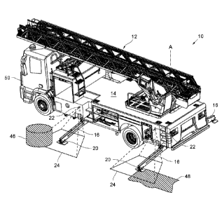
The firefighting vehicle 10. in Fig. 1 is one example of a utility
vehicle according to the present invention. The firefighting vehicle
is equipped with a turnable ladder 12 on its top that is turnable
around a vertical axis A and comprises a number of ladder segments
that are slidably supported on each other so that the ladder 12 is
extractable. If this extraction of the turnable ladder 12 is performed
in a position where the ladder 12 is swiveled in lateral direction,
i.e. in a right angle from the non-use position shown in Fig. 1, the
weight of the ladder acts to tilt the vehicle body 14 around its
horizontal longitudinal axis. To support the vehicle 10 safely on the
ground, it is therefore necessary to provide an additional support
means at the sides of the vehicle.
Ground supports 16 are provided at the sides of the vehicle body 14.
These supports 16 comprise bars that extend in mainly horizontal
direction from the lower part of the vehicle body 14 in the lateral
direction, i.e. rectangular to
CA 2888374 2019-11-11
W02014/060476 PCT/EP2013/071626
9
the driving direction. These bars are extractable so that the
supports 16 are movable between retracted positions, in which
the outriggers 16 are positioned under the vehicle body 14 so
that they do not protrude in a lateral direction
from the vehicle, and extracted operation positions, as shown
in Fig. 1, in which the ends 20 of the supports 16 rest on
the ground in a distance from the respective sides from the
vehicle 10. The contact to the ground is achieved by tilting
the support 16 slightly downward, as in the pre-
sent embodiment of the vehicle 10, or by any other suitable
mechanism. A very common construction of supports 16 com-
prises jacks at their ends that have lower contact surfaces
that can be pressed onto the ground in the operating posi-
tion. However, the present invention is not limited to any
construction but can refer to any suitable supporting mecha-
nism of the supports 16.
When positioning the firefighting vehicle 10 in a rescue
situation, maneuvering of the vehicle 10 can be difficult to
find a position in which the supports 16 can find suitable
operating positions. This is because the operating positions
must be estimated by the driver of the vehicle 10, and this
may be difficult at narrow places with obstacles in the lat-
eral ground area, like parking cars, plant pots, etc. Another
difficulty lies in finding a piece of ground to sup-
port the ends 20 of the supports 16 that is solid enough to
35298963529-89g
CA 2888374 2019-11-11
CA 028374 201.04-15
WO 2014/060476 PCT/EP2013/071626
resist against the forces acting onto the outriggers 16.
Lawn areas etc. do not provide a sufficient resistance. In
particular in situations with poor sight conditions, the
driver of the vehicle 10 is often unable to monitor the area
5 for placing the end 20 of the supports 16 accordingly, and
he needs the help of another person for maneuvering the ve-
hicle 10 and extracting the supports 16.
These problems of common firefighting vehicles are overcome
by the firefighting vehicle 10 according to the present in-
10 vention, which is equipped with a monitoring system. It com-
prises surveillance cameras at the side of the vehicle 10.
In the present embodiment, there are four supports 16,
namely two supports 16 at each side of the vehicle arranged
in a distance, and there are also four surveillance cameras
22, each camera 22 being allocated to one supports 16. The
respective camera 22 is fixed at the vehicle body 14 in an
elevated position above its allocated supports 16, and its
viewing angle is provided such that it comprises the ground
area 24 on which the end 20 of the support 16 rests in its
operating position. The viewing angle of the cameras 22 is
slightly tilted in a downward direction to provide a per-
spective view from above to the ground area 24 for position-
ing the end 20 of the support 18.
Each camera is provided to generate a set of real time image
data, representing a present image of the respective ground
11
area 24. With other words, each 'camera 22 takes a real time image of
the ground area 24.
For processing the sets of image data generated by the cameras 22,
the monitoring system further comprises a control unit 26 shown
schematically in Fig. 2, which further shows other components of the
monitoring system 28, namely the cameras 22 and a visual display 30
for showing images 32 corresponding to the image data of the cameras
22 that are processed by the control unit 26. From each set of image
data provided by one camera 22, corresponding to a picture of the
monitored ground area 24 in the visual field of the camera, the
control unit 26 generates an image 32. However, the image 32 does not
show the ground area 24 alone but also the expected operating
positions of the outriggers 16 as visual markings 34. These markings
34 can be rendered from pre-stored data representing expected
operating positions of the supports, or from calculated data
representing these expected operating positions. The control unit 26
is provided to combine the real-time image data generated by the
cameras 22 with the calculated or pre-stored data related to the
expected operating positions of the supports 16 to generate images 32
from these combined data in which the expected operating positions of
the supports 16 are visualized by visual markings 34, superposed to
the image of the ground area 24.
CA 2888374 2019-11-11
12
Another option is to fix the visual markings 34 permanently to the
screen of the visual display 30 and to render the electronic image 32
by means of the display 30 so that both the image 32 and the permanent
markings 34 are superposed.
The expected operating positions of the supports 16, that are clearly
defined within the visual field of the camera 22, can be related to
the present position of the vehicle 10 on the ground to anticipate a
possible collision of the supports 16 with an obstacle within the
ground area 24, or to judge the ground conditions so as to avoid the
placement of the end 20 of the support 16 onto a soft ground. In
particular it is noted that the visual markings 34 enable the
operator, for example the driver of the vehicle 10 to anticipate the
operating position of the outrigger 16 before the support 16 reaches
this position, before extracting the support 16 from its retracted
position, to avoid a collision or any other mistake in placing the
support 16.
As it is shown in more detail in Fig. 3, which is an exemplary
screenshot of the visual display as one example, the images 32 of all
cameras 22 are shown at the same time in a split screen manner. The
whole screen area 30 is divided in four parts of equal height and
width. The upper left area 38 shows the image 32 corresponding to the
front left camera 22 above the front left support 16 of the vehicle
10, the upper right area 40 corresponds to the front right camera 22,
the
CA 2888374 2019-11-11
13
bottom left area 42 corresponds to the rear left camera 22, and the
remaining bottom right area 44 corresponds to the rear right camera
22. The visual markings 34 showing the expected operating positions
of the supports 16 and are also shown in the respective images in the
areas 38,40,42,44. When the outrigger finally reaches its extracted
operating position, this will correspond to the visual marking 34.
The actual picture of the outrigger 16 moving into the visual field
of the camera 22 will be apparent in the image 32 captured by the
camera 22. Moreover, objects within the visual field of the camera,
i.e. obstacles in the ground area 24 will also be visible in this
picture 32. As one example of such an object that is also shown in
Fig. 1, a plant pot 46 within the ground area 24 one which the end 20
of the front left support 16 is supported is shown in the image 32 of
the screen area 38. The operator will then be able to estimate whether
there will be a collision of the support 16 with the object 46 by
estimating the distance between the end of the visual marking 34 and
the object 46. This estimation may be supported by marking also the
object 46 by a corresponding visual marking. Moreover, the distance
between the end of the visual marking 34 of the support 16 and the
object 46 (or its visual marking, respectively) can be calculated by
the control unit 26 and visualized by fading in the calculated
distance within the image. It is also poss-
CA 2888374 2019-11-11
CA 02888374 2015-04-15
WO 2014/060476 PCT/EP2013/071626
14
ble to calculate other distances by means of the control
unit 26, for example, the distance between the object 46 and
the vehicle body 14 and/or the distance between the present
operating position of the support 16 and the object 46
(which is to be distinguished from the expected operation
position of the support represented by the visual marking
34).
If the ground area 24 includes a soft ground portion that is
not suitable for placing the end 20 of the support 16, this
will also be visible in the respective image 32 in case the
visual marking 34 of the expected operating position of the
support 16 and the unsuitable ground area portion overlap.
For example, in the bottom left screen area 42, the portion
of lawn 48 is shown that is captured by the camera 22 on the
rear left side of the vehicle 10. This lawn portion 48 (see
also Fig. 1) overlaps with end of the visual marking 34,
which means that there will be a positioning error which
must be corrected by the driver of the vehicle 10 by maneu-
vering the vehicle 10. Other unsuitable areas may be man
hole covers of the sewer network, drain pits or the like.
As one possible option, the cameras 22 are provided with in-
frared sensors to provide a good visibility even in a dark
environment with poor sight.
CA 028374 201.04-15
WO 2014/060476 PCT/EP2013/071626
For placing the firefighting vehicle 10 in a way that the
turnable ladder 12 can be operated without colliding with
obstacles, it is helpful to visualize the vertical turning
axis A (Fig. 1) of the turnable ladder 12 on the visual dis-
5 play 30. In Fig. 3, this axis A is marked on the screen 36
between the left and right bottom screen areas 42 and 44,
showing the position of the vertical axis A with respect to
the expected operating positions of the supports 16. It
might also be possible to calculate the distance between the
10 axis A and any obstacles in the environment of the vehicle
10, for example, the distance to a wall next to the vehicle
10, and to fade in this distance as a number or any visual
marking. It will also be possible to highlight all markings
in the respective image 32, including the visual marking 34
15 for the expecting operating position of the support 16, a
visual marking showing an object 46 or any ground portion
48, according to the decision whether there is an overlap
between the visual marking 34 and any other of the markings.
This decision can be made by control unit 26. Such a high-
lighting feature may be interpreted as an alert by the op-
erator to avoid any collision or positioning mistake. In
case there is such an overlap of markings, indicating a col-
lision, or any other positioning mistake, there can also be
an acoustic alert to the operator.
CA 02888374 2015-04-15
WO 2014/060476 PCT/EP2013/071626
16
As described above, all images 32 generated from the real
time image data provided by the cameras 22 are shown at the
same time in a split screen manner on the visual display.
This enables the operator to judge the positioning of the
supports 16 at different portions around the vehicle 10 at
the same time, without having to change his own position to
monitor the different ground areas 24 on eyesight without
technical means. The visual display 30 can be mounted in the
driver's cabin 50 (Fig. 1) of the vehicle 10, so that the
driver can watch the visual display 30 with the split screen
showing all four images 32 in different areas 38,40,42,44 of
the screen area 36 and maneuver the vehicle 10 at the same
time.
The present invention is not only applicable to firefighting
vehicles 10 but also to any other utility vehicles, espe-
cially those with an aerial apparatus like a turnable ladder
or an aerial platform on top.