Note: Descriptions are shown in the official language in which they were submitted.
CLAMPING ASSEMBLY
This invention relates to clamping assemblies.
More particularly, but not
exclusively, this invention relates to clamping assemblies for clamping
elongate
articles, such as wires, wire ropes or the like. Embodiments of the invention
relate to
clamping assemblies comprising clamping members urged to a clamping condition
by means of urging means.
Clamping assemblies for clamping wire, wire rope or the like are known. For
example, patent specification No. GB2240581 discloses a connector comprising a
body having a passage and clamping member for clamping a wire in the passage.
However, releasing the wire can only be effected by manipulating the wire.
According to the present invention, there is provided a clamping assembly
comprising
a body defining a passage through which an elongate article is extendable, a
clamping
member arranged in the passage for clamping the elongate article, the clamping
member being movable between clamping and release conditions for respectively
clamping and releasing the article, and urging means comprising a pair of
springs to
urge the clamping member along the passage to the clamping condition, wherein
the
springs extend externally of the body opposite each other and is deformable by
pressing the pair of springs towards each other to a release configuration to
urge the
clamping member to the release condition, and wherein the body comprises first
and
second opposed walls defining said passage, the second wall extending at an
acute
angle to said first wall, and the clamping member being movable to clamp the
elongate article against the first wall, and the clamping member being
arranged in the
passage so that it is pullable by the elongate article along the passage in
engagement
with the second wall to clamp the elongate article against the first wall.
Preferred embodiments are described hereunder.
1
CA 2888414 2018-01-16
According to the present invention, there is provided a clamping assembly
comprising a body defining a passage through which an elongate article can
extend,
a clamping member arranged in the passage for clamping the elongate article,
the
clamping member being movable between clamping and release conditions for
respectively clamping and releasing the article, and urging means comprising a
pair
of springs to urge the clamping member to the clamping condition, wherein the
springs extend externally of the body opposite each other and can be deformed
by
pressing the pair of springs towards each other to a release configuration to
urge
the clamping member to the release condition.
According to one aspect of this invention, there is provided a clamping
assembly
comprising a body defining a passage through which an elongate article can
extend,
a clamping member arranged in the passage for clamping the elongate article,
the
clamping member being movable between clamping and release conditions for
respectively clamping and releasing the article, and urging means comprising a
spring to urge the clamping member to the clamping position, wherein the
spring
can be deformed to a release configuration to urge the clamping member to the
release condition.
According to another aspect of the invention, there is provided a clamping
assembly
comprising a body defining a passage through which an elongate article can
extend,
a clamping member arranged in the passage for clamping the elongate article,
the
clamping member being movable between a clamping condition in which the
clamping member can clamp the article, and a release condition in which the
article
can be released, and urging means, wherein the urging means comprises a spring
to urge the clamping member to the clamping condition.
The urging means may provide a release means for urging the clamping member to
the release condition. The spring may comprise a tension spring. The spring
may
la
CA 2888414 2018-01-16
be deformable to a deformed configuration by applying a release force thereto.
Preferably, the spring can be deformed by applying the release force thereto
transverse to the direction of movement of the clamping member between the
clamping and release conditions. The release force may be applied in a
direction
lb
CA 2888414 2018-01-16
CA 02888414 2015-04-14
WO 2014/064403
PCT/GB2013/000441
towards the body. The deformation of the spring desirably urges the clamping
member to the release condition.
In the embodiment described herein, the application of the release force to
the spring
causes the spring to push the clamping member to the release condition.
The spring may extend externally of the body, thereby allowing the user to
apply said
release force thereto, for example, by pressing the spring with his or her
finger.
The urging means may hold the clamping member. The urging means may
comprise a carriage attached to the spring, wherein the carriage carries the
clamping
member. The carriage may define a space in which the clamping member is
received.
The clamping assembly may further include anchor means to anchor the urging
means to the body. The anchor means may comprise an anchor portion and the
body may include cooperating means to cooperate with the anchor portion and
anchor the urging means to the body.
The cooperating means may comprise a holding formation for holding the anchor
portion. The holding formation may be an aperture or recess to receive the
anchor
portion. The aperture or recess may be defined in the body. The urging means
may
include the anchor portion. In a first embodiment, the anchor portion may be
attached to the spring by an attaching member.
The holding formation may be a slot to receive the anchor portion. In one
embodiment, the slot may be an upwardly facing slot. In another embodiment,
the
slot may be a side facing slot.
The urging means may comprise a further spring, thereby comprising a pair of
said
springs. The further spring may comprise a tension spring. Each spring may be
attached to the carriage. The anchor member may be attached to both springs by
the attaching member. The, or each, spring may extend externally of the body.
The,
or each, spring may comprise an elongate strip, which may be a substantially
flat
strip.
2
CA 02888414 2015-04-14
WO 2014/064403
PCT/GB2013/000441
In a second embodiment, the anchor portion may extend between the pair of
springs,
and may comprise a connecting member to connect the springs to each other. The
connecting member may be substantially flat.
The, or each, spring may comprise an elongate curved member. The curved
member may curve outwardly way from the body. The urging means may be in the
foi __ of a ring. The, or each, spring may comprise a flat spring.
The urging means may be deformed by pressing the pair of springs towards each
other. Both springs may be pressed towards the body to effect said movement of
the clamping member to the release condition.
The clamping member may comprise a roller, which may be in the form of a
cylindrical member or a ball. Alternatively, the clamping member may comprise
a
wedge.
The body may comprise a first wall partly defining said passage. The clamping
member may be movable substantially parallel to said first wall. The clamping
member may clamp the elongate article against the first wall.
The body may include a second wall partly defining said passage, the second
wall
extending at an acute angle to said first wall. The clamping member may be
movable along said passage from the release condition to the clamping
condition.
The carriage may have a first face substantially parallel to the first wall
and a second
face substantially parallel to the second wall.
The second wall may be a reaction wall to apply a reaction force to said
clamping
member when the clamping member clamps the article against the first wall. The
second wall may taper towards the first wall in the direction in which the
clamping
member moves from the release condition to the clamping condition.
The, or each spring, may be formed of a plastics material.
The clamping assembly may include securing means for securing the clamping
assembly to an ancillary member. In one embodiment, the securing means may
comprise a securing member, which may be configured to be received by a
portion
of the ancillary member, or which may be configured to receive a portion of
the
ancillary member.
3
CA 02888414 2015-04-14
WO 2014/064403
PCT/GB2013/000441
In another embodiment, the securing means may comprise a recess which can
receive a projection on the ancillary member. The recess may be defined by the
body. Alternatively, the securing means may comprise a projection which can be
received by a recess defined by the ancillary member.
The body may define a pair of opposed recesses or a pair of opposed
projections.
Embodiments of the invention will now be described by way of example only with
reference to the accompanying drawings, in which:
Figure 1 is a front view of a first embodiment of a clamping assembly;
Figure 2 is a view along the lines II ¨ 11 in Figure 1;
Figure 3 is a side view of the first embodiment of the clamping assembly;
Figure 4A is view along the lines IV ¨ IV in Figure 3, showing a clamping
member in
a clamping condition;
Figure 4B is a view which is similar to Figure 4A, but which shows the
clamping
member in a release condition;
Figure 5 is an exploded view of the first embodiment of the clamping assembly.
Figure 6 is a perspective view of a second embodiment of a clamping assembly;
Figure 7 is an exploded view of the first second of the clamping assembly.
Figure 8A is sectional view along the lines VIII ¨VIII in Figure 3, showing a
clamping
member in a clamping condition;
Figure 8B is a view which is similar to Figure 8A, but which shows the
clamping
member in a release condition; and
Figure 9 is a sectional view along the lines IX ¨ IX in Figure 6.
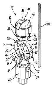
Referring to the Figures 1 to 5 of the drawings, there is shown a clamping
assembly
for clamping an elongate article 100 in the form of a wire, wire rope or the
like.
The clamping assembly 10 comprises a body 12, urging means 14 and a clamping
member 16 for clamping the elongate article within the body 12.
4
CA 02888414 2015-04-14
WO 2014/064403
PCT/GB2013/000441
The clamping member 16 is movable from a clamping condition shown in Figure 4A
to a release condition shown in Figure 4B. In the embodiment described herein,
the
clamping member 16 is in the form of a cylindrical roller.
The urging means 14 comprises a ring 18 formed of a pair of springs 20 in the
form
of tension springs. Each spring 20 is in the form of an elongate curved
member,
which curves outwardly away from the body 12, as shown most clearly in Figures
1,
4A and 4B. Each spring 20 is in the form of a substantially flat strip.
The urging means 14 further includes a carriage 22, in the form of a
substantially
square member, integrally attached to the springs 20. The springs 20 extend
outwardly from the carriage 22 on opposite sides thereof. The carriage 22
defines a
space 24 in which the clamping member 16 is carried.
The urging means 14 also includes an anchor portion 26, which is attached to
the
springs 20 via an attaching member 28. Each spring 20 extends from the
carriage
22 to the attaching member 28.
The body 12 includes a domed upper region 30 defining a holding formation in
the
form of an upwardly facing slot 32. The anchor portion 26 is received in the
upwardly facing slot 32 and held therein to secure the urging means 14 to the
body
12.
The body 12 further defines a passage 34 in which the carriage 22 and the
clamping
member 16 are held. The body 12 also includes a securing member in the form of
a
securing portion 38 opposite the upper region 30.
The securing portion 38 is provided to secure the body 12 to an ancillary
member 40
to attach the clamping assembly to, for example, a load, such as mounted on a
threaded rod. The ancillary member 40 defines a mouth portion 42 to receive
the
securing portion 38, thereby securing the body 12 to the ancillary member 40.
A first opening 36 is defined in the body 12, and extends across the securing
portion
38 opposite the upper region 30. The first opening 36 provides communication
between the passage 34 and the region outside the body 12. The first opening
36
allows the carriage 22 to be received in the passage 34. The springs 20 extend
through the first opening 36 to the carriage 22 in the passage 34. The
ancillary
CA 02888414 2015-04-14
WO 2014/064403
PCT/GB2013/000441
member 40 defines an associated second opening 37 which is aligned with the
first
opening 36 when the ancillary member 40 is secured to the body 12. Thus, the
springs 20 extend from the attaching member 28 in opposite directions around
the
body 12 to the carriage 22 in the passage 34, through the first opening 36 and
the
associated opening 37.
Referring specificaliy to Figure 2, the passage 34 defined in the body 12
extends
through the upper region 30 to a second opening 44 opposite the first opening
36.
Thus, the elongate article 100 can extend through the passage 34, entering and
exiting the body 12 via the first and second openings 36, 44.
The passage 34 is defined between first and second internal walls 46, 48 of
the body
12. The elongate article 100 extends along the first wall 46. The second wall
48 is
arranged at an acute angle to the first wall 46, and tapers towards the first
wall 46 in
the direction from the first opening 36 to the second opening 44.
The carriage 22 has a first face 50 which faces the first wall 46 and extends
substantially parallel thereto. The carriage 22 also has a second face 52
which
faces the second wall 48 and extends substantially parallel to the second wall
48.
In use, the ancillary member 40 is secured to the body 12, and the elongate
article
100 is threaded through the passage 34 in the body 12 in the direction
indicated by
the arrow A in Figure 2. When the clamping assembly 10 is at a desired
position on
the elongate article 100, the elongate article 100 is then moved in the
opposite
direction, as indicated by the arrow B in Figure 2.
The springs 20, being under tension, pull the carriage 22 and the clamping
member
16 in the direction indicated by the arrow B, and into engagement with the
elongate
article and the second wall 48. In addition, movement of the elongate article
in the
direction indicated by the arrow B, when the clamping member engages the
elongate
article 100 further pulls the carriage 22 and the clamping member 16 in the
same
direction.
The tapering of the second wall 48 towards the first wall 46 forces the
clamping
member 16 into tighter engagement with the elongate article 100 as a result of
such
movement, thereby clamping the elongate article 100 to the gripping assembly
10.
Figures 2 and 4A show the carriage 22 holding the clamping member 16 in the
6
CA 02888414 2015-04-14
WO 2014/064403
PCT/GB2013/000441
clamping condition in which the clamping member 16 clamps the elongate article
100.
The position of the clamping assembly 10 along the elongate member 100 can be
adjusted, for example, if the user realises that the clamping assembly 10 has
been
arranged on the elongate article 100 in the wrong position. This can be done
by
pressing inwardly on the springs 20 as shown =by the arrows X in Figure 4A and
48,
to deform them to a release configuration shown in Figure 4B. Such deformation
of
the springs 20 pushes the carriage 22 and the clamping member 16 from the
clamping condition shown in Figure 4A to the release condition shown in Figure
4B.
When the clamping member 16 is in the release condition, the elongate article
100 is
not clamped by the clamping member 16, thereby allowing the clamping assembly
to be moved along the elongate member 100 to the correct position. The
clamping assembly 10 can then be clamped to the elongate article 100 as
described
above.
Various modifications can be made without departing from the scope of the
invention. For example, the clamping member could be a spherical member or a
wedge shaped member.
There is =thus described a clamping assembly 10 for clamping an elongate
article
100, in which the clamping member 16 can be easily released from the clamping
condition to the release condition by pressing inwardly on the springs 20.
A second embodiment of the clamping assembly 10 is shown in Figures 6 to 9.
The
second embodiment of the clamping assembly 10 includes many of the features of
the first embodiment shown in Figures 1 to 5. In Figures 6 to 9, the features
of the
first embodiment that are present in the second embodiment are designated with
the
same reference numerals as in Figures 1 to 5.
The second embodiment differs from the first embodiment in that the upper
region 30
defines a side facing slot 132. A further difference is that the urging means
14
comprises an anchor portion in the form of a substantially flat connecting
member
126.
7
CA 02888414 2015-04-14
WO 2014/064403
PCT/GB2013/000441
The connecting member 126 connects the springs 20 to each other at the top of
the
urging means 14. The connecting member 126 is received in the side facing slot
132 from outside the body 12, and is thus held by the body 12. The connecting
member 126 defines a cooperating recessed formation 127 to cooperate with a
protrusion 128 in the side facing slot 132 (see Figures 7, 8A and 8B).
The carnage 22 and the clamping member 16 are held in the passage 34 in the
body
12 in the same way as the first embodiment. The second embodiment thus
operates
in the same way as the first embodiment.
Another difference is that the body 12 includes a pair of opposed securing
formations
in the form of two recesses 138A, 138B defined by the body 12. An ancillary
member 140 includes a pair of opposed projections 142A, 1428 which can be
received in the recesses 138A, 138B, thereby securing the ancillary member to
the
body 12. The ancillary member 140 includes a sloped wall 144 along which the
elongate article 100 can extend when the elongate article 100 is clamped by
the
clamping member 16.
The ancillary member may have a fastening formation 150, such as a threaded
bore,
to fasten a further article (not shown), such as a threaded rod, thereto.
Figures 8A and 8B show sectional views of the second embodiment of the
clamping
assembly 10 in the clamping and release conditions. Figure 8B shows the urging
means 14 in a release configuration. These views are similar to the views
shown in
Figures 4A and 48.
The above described embodiments have the advantage that there is no need for
an
end cap. Instead the ancillary members 38, 140 are Provided, which can be
replaced by a different ancillary members 38, 140, thereby allowing the
clamping
assembly to perform different functions. The above described embodiments also
have the advantage that the clamping member 16 is devoid of teeth, and can be
formed of zinc, thereby reducing expense.
Further advantages of the above described embodiments are that the number of
parts is reduced as compared with prior art designs, and the ability to move
the
clamping member 16 to the release condition, i.e. by pressing inwardly on the
springs 20, allows much easier release than with prior art designs.
8
CA 02888414 2015-04-14
WO 2014/064403
PCT/GB2013/000441
The second embodiment has the further advantage that by providing a slot 132
in
the side of the body 12, removal of the urging means 14, and the clamping
member
16 is simplified.
9