Note: Descriptions are shown in the official language in which they were submitted.
CA 02888788 2015-04-17
WO 2014/063123
PCT/US2013/065798
IMPROVED AUTOINJECTOR
FIELD
[0001] The present disclosure relates to autoinjector devices. More
particularly, the
present disclosure relates to an autoinjector device having a skin stretching
and pinching
capability, an ergonomic autoinjector holding device, and other ergonomic
improvements
for autoinjectors.
BACKGROUND
[0002] Autoinjector (AI) devices are held against the body while an
injection needle
pierces the skin to administer a drug product. While gripping the Al, the user
applies a
downward movement against the skin that activates the AL The user then presses
a
button to cause the needle to inject and the stopper to move the drug downward
into the
skin.
[0003] During needle insertion and plunger movement, the interface/surface
area
between the user's skin and the AI's physical area touching the skin (and
encompassing
the needle) must remain in place to avoid AT and/or needle slippage or
movement on the
surface of the skin. This must occur to enable a full drug dose delivery, to
avoid drug
leakage on the skin's surface, and most importantly, to avoid user injury from
a bent or
broken needle during the injection process. Additionally, for user comfort, it
is advised
that the injection site's skin area, and directly under the Al, be kept taut
to facilitate the
injection procedure.
1
CA 02888788 2015-04-17
WO 2014/063123
PCT/US2013/065798
[0004] Today's AT procedures advise users to stretch or pinch the skin at
the injection
site with one hand and to maintain that stretch or pinch while placing the Al
over the
same area. With the Al in place, the user applies a downward force on the site
area to
activate or unlock the device. While keeping the skin stretched or pinched
with one hand
and the Al gripped in position with the other, the user must then use the
thumb of the
hand holding the Alto depress a button located at the top of the Al, thereby,
activating
needle and plunger downward movement to inject the drug. After the injection
is
completed, the needle may be retracted from the skin and the user lifts off
the device.
[00051 During the act of placing and activating the Al onto the site, users
have been
observed to: 1) lose concentration, letting go of the stretched or pinched
skin, and
attempting to maneuver the Al into place; 2) let go of the stretched or
pinched skin in
order to grip the AT with two hands due to their lack of physical hand
strength or
dexterity; and 3) lift the device off too soon before the injection is
complete. Further, the
use of AIs can be a significant challenge for seniors or finger function
compromised users
and consequently, treatment can be hindered.
[0006] Hence, there are multiple considerations for the front wall at the
injection end
of the Al. One such consideration is the AI's ability to stretch skin. The
user is not
expected to stretch the skin while injecting with the Al, therefore, it would
be very
beneficial to have a feature on the Al that will provide this function.
Another
consideration is to provide the Al with a feature that improves the stability
of the Al, so
that it remains approximately perpendicular to the body during injection,
thereby
allowing the user to operate the AT with one hand. Still another consideration
is that some
commercial AIs require the application of an axial force to a trigger release
mechanism
81786725
on the front wall of the AT where it contacts the user's skin. Some body types
have lower surface
tension and resistance to the required activation force thereby causing the
Alto press against the
skin and deflect into the body a significant amount. Some patients do not
apply the required
activation force thereby not allowing the Alto arm and be ready to inject.
Some commercial AIs
have a shield trigger and activation button which must be pressed to arm and
initiate delivery.
Other commercial AIs only require a shield trigger to be pressed to arm and
initiate delivery.
[0007] Accordingly, methods are needed which solve the placement,
activation, and
ergonomic design issues of conventional AIs.
SUMMARY
[0008] According to an aspect of the present invention, there is provided
an injector
comprising: a housing having an injection end; an injection needle enclosed
within the housing,
the injection needle penetrating skin at a selected injection site and
dispensing a drug product
when an injection cycle of the injector is activated; a flexible extension
disposed at the injection
end of the housing for stretching or pinching the skin of the injection site;
and an adaptor for
attaching to the housing, the flexible extension being removably attached to
the adaptor.
[0008a] According to another aspect of the present invention, there is
provided a device for
use with an injector having an injection needle, the device comprising a
flexible extension for
attaching to an injection end of the injector, the flexible extension for
stretching or pinching skin
at a selected injection site, and an adaptor for attaching to a housing of the
injector, the flexible
extension being removably attached to the adaptor.
[0009] One aspect provides an injector comprising a housing having an
injection end, an
injection needle enclosed within the housing, the injection needle penetrating
skin at a selected
3
Date Recue/Date Received 2020-08-26
81786725
injection site and dispensing a drug product when an injection cycle of the
injector is activated,
and a flexible extension disposed at the injection end of the housing for
stretching or pinching the
skin of the injection site.
[0009a] In some embodiments of the injector, the flexible extension may be
integral with the
housing.
[0010] In some embodiments of the injector, the flexible extension may be
removably
attached to the housing.
[0011] Some embodiments of the injector may further comprise a locking
arrangement for
removably attaching the flexible extension to the housing, the locking
arrangement including
interlocking first and second members, the flexible extension
3a
Date Recue/Date Received 2020-08-26
CA 02888788 2015-04-17
WO 2014/063123
PCT/US2013/065798
including one of the first and second members and the housing including the
other one of
the first and second members.
[0012] In some embodiments of the injector, the flexible extension may be
selected
from a kit of flexible extensions, wherein one of the flexible extensions of
the kit may be
constructed to stretch the skin of the injection site and wherein another one
of the flexible
extensions of the kit may be constructed to pinch the skin of the injection
site.
[0013] In some embodiments of the injector, the flexible extension is non-
removably
attached to the housing of the injector.
[00141 Some embodiments of the injector may further comprise an adaptor for
attaching to a housing of the injector, wherein the flexible extension may be
removably
attached to the adaptor.
[0015] Some embodiments of the injector may further comprise a locking
arrangement for removably attaching the flexible extension to the adaptor, the
locking
arrangement including interlocking first and second members, the flexible
extension
including one of the first and second members and the adaptor including the
other one of
the first and second members.
[0016] In some embodiments of the injector, the flexible extension is
constructed as a
flange.
[0017] In some embodiments of the injector, the flexible extension is made
of a
polyurethane or silicon-polyurethane copolymer material.
[0018] Some embodiments of the injector may further comprise a needle
shield for
covering the injection needle upon withdrawal of the injection needle from the
skin of the
injection site.
4
CA 02888788 2015-04-17
WO 2014/063123
PCT/US2013/065798
[00191 In some embodiments of the injector, the flexible extension may be
integral
with the needle shield.
[00201 In some embodiments of the injector, the flexible extension may be
removably
attached to the needle shield.
[0021] In some embodiments of the injector, the needle shield may be
colored for
indicating completion of the injection cycle.
[0022] Some embodiments of the injector may further comprise a soft guard
attached
to the needle shield, the guard for preventing the needle shield from
contacting the skin at
the injection site.
[0023] In some embodiments of the injector, the flexible extension may have
one or
more ring-shaped protrusions or ridges formed in or on a working surface of
the
extension.
[0024] In some embodiments of the injector, the flexible extension may have
a
plurality of nubs formed in or on a working surface of the extension.
[0025] In some embodiments of the injector, the flexible extension may have
a grippy
or textured working surface.
[00261 Some embodiments of the injector may further comprise a palm button
device
for at least activating the injection cycle of the injector.
[0027] In some embodiments of the injector, the palm button device may have
a
mushroom shaped palm button.
[0028] In some embodiments of the injector, the palm button device may have
a
handle shaped palm button.
CA 02888788 2015-04-17
WO 2014/063123
PCT/US2013/065798
[00291 In some embodiments of the injector, the palm button device may
comprise a
palm button having at least one indent for placement of a user's thumb.
[00301 In some embodiments of the injector, the palm button may have a
polyurethane
gel elastomer coating.
[00311 In some embodiments of the injector, the palm button device may be
integral
with the injector.
[00321 In some embodiments of the injector, the palm button device may be
removably attached to the housing of the injector.
[00331 In some embodiments of the injector, the palm button device may be
non-
removably attached to the housing of the injector.
[00341 In some embodiments of the injector, the palm button device may
comprise a
palm button and a mounting arrangement for operatively coupling the palm
button to the
injector.
[00351 In some embodiments of the injector, the mounting arrangement may
comprise
a base extending from the palm button and an adaptor for attaching to a
housing of the
injector, wherein the base is movably coupled to the adaptor.
[00361 Some embodiments of the injector may further comprise a holding
device for
aiding a user in the operation of the injector, the holding device comprising
a sleeve for
ergonomically holding and operating the injector with one hand and at least
one hand rest
extending out from the sleeve for maintaining a user's hand on the sleeve when
holding
and operating the injector.
[00371 In some embodiments of the injector, the sleeve of the holding
device may
have a polyurethane gel elastomer layer that defines a hand grip.
6
CA 02888788 2015-04-17
WO 2014/063123
PCT/1JS2013/065798
[0038] In some embodiments of the injector, the sleeve may have a top wall
operative
as stop for properly positioning the sleeve on the injector so that a user can
operate the
injector with one hand.
[0039] In some embodiments of the injector, the top wall may include an
opening for
allowing an activation button of the injector to extend through the top wall.
[0040] In some embodiments of the injector, the at least one hand rest may
pivotally
couple to the sleeve.
[0041] In some embodiments of the injector, the at least one hand rest may
include a
projection that engages a side wall of the housing if the at least one hand
rest is in a
clamping position, thereby removably attaching the holding device to the
injector.
[0042] In some embodiments of the injector, the holding device may further
comprise
a detent arrangement for retaining the at least one hand rest in the clamping
position.
[0043] In some embodiments of the injector, the at least one hand rest may
be
contoured to receive the hypothenar muscle area of the user's hand.
[0044] In some embodiments, of the injector, the holding device may be
integral with
the injector.
[0045] In some embodiments of the injector, the holding device may be
removably
attached to the housing of the injector.
[0046] In some embodiments of the injector, the holding device may include
a locking
arrangement for non-removably attaching the holding device to the housing of
the
injector.
[0047] In some embodiments of the injector, the holding device may allow a
user to
arm and initiate the injection cycle of the injector.
7
CA 02888788 2015-04-17
WO 2014/063123
PCT/1JS2013/065798
[0048] In some embodiments of the injector, the holding device may allow a
user to
initiate the injection cycle of the injector.
[0049] In some embodiments of the injector, the sleeve may be capable of
slidably
moving on the housing of the injector to initiate the injection cycle of the
injector
[0050] Further, an injector comprising a housing having an activation end
and an
injection end disposed opposite to and indite with the activation end, and
further
comprising the earlier described palm button device disposed at the activation
end of the
housing, wherein the palm button device activates an injection cycle of the
injector.
[00511 Still further, an injector comprising a housing and the holding
device described
earlier, for aiding a user in the operation of the injector.
[0052] Still further, a skin manipulating device for use with an injector
having an
injection needle, the device comprising a flexible extension for stretching or
pinching
skin at the selected injection site.
[0053] In some embodiments of the skin manipulating device, the flexible
extension
may have one or more ring-shaped protrusions or ridges formed in or on a
working
surface thereof.
[0054] In some embodiments of the skin manipulating device, the flexible
extension
may have a plurality of nubs formed in or on a working surface thereof.
[0055] In some embodiments of the skin manipulating device, the flexible
extension
may have a grippy or textured working surface.
[0056] In some embodiments of the skin manipulating device, the flexible
extension
may be integral with the injector.
8
CA 02888788 2015-04-17
WO 2014/063123
PCT/US2013/065798
[00571 In some embodiments of skin manipulating device, the flexible
extension may
be removably attached to the injector.
[00581 In some embodiments of the skin manipulating device, the flexible
extension
may further comprise an adaptor to be attached to a housing of the injector,
the flexible
extension being removably attachable to the adaptor.
[0059] Some embodiments of the skin manipulating device may further
comprise a
locking arrangement for removably attaching the flexible extension to the
adaptor, the
locking arrangement including interlocking first and second members, the
flexible
extension including one of the first and second members and the adaptor
including the
other one of the first and second members.
[0060] Still further, a holding device for aiding a user in the operation
of an injector.
The holding device may comprise a sleeve for ergonomically holding and
operating the
injector with one hand, and at least one hand rest extending out from the
sleeve for
maintaining a user's hand on the sleeve when holding and operating the
injector.
[0061] In some embodiments of the holding device, the sleeve may have a
polyurethane gel elastomer layer that defines a hand grip.
[0062] In some embodiments of the holding device, the sleeve may have a top
wall
operative as stop for properly positioning the sleeve on the injector so that
a user can
operate the injector with one hand.
[0063] In some embodiments of the holding device, the top wall may include
an
opening for an activation button of the injector.
[0064] In some embodiments of the holding device, the at least one hand
rest may be
pivotally coupled to the sleeve.
9
CA 02888788 2015-04-17
WO 2014/063123
PCT/1JS2013/065798
[00651 In some embodiments of the holding device, the at least one hand
rest may
include a projection for engaging a side wall of the housing, if the at least
one hand rest is
in a clamping position, thereby allowing removable attachment of the holding
device to
the injector.
[00661 Some embodiments of the holding device may further comprise a detent
arrangement for retaining the at least one hand rest in the clamping position.
100671 In some embodiments of the holding device, the at least one hand
rest may be
contoured to receive the hypothenar muscle area of the user's hand.
[00681 Some embodiments of the holding device may further comprise a
locking
arrangement for non-removably attaching the holding device to the housing of
the
injector.
[00691 Some embodiments of the holding device may allow a user to initiate
the
injection cycle of the injector.
[00701 In some embodiments of the holding device, the sleeve may be capable
of
being slidably moved on the housing of the injector to initiate the injection
cycle of the
injcctor.
[00711 Still further, a palm button device for at least activating an
injection cycle of an
injector. The palm button device may comprise a palm button and a mounting
arrangement for operatively coupling the palm button to the injector.
[00721 In some embodiments of the palm button device, the mounting
arrangement
may comprise a base extending from the palm button and an adaptor for
attaching to a
housing of the injector, wherein the base movably coupled to the adaptor.
CA 02888788 2015-04-17
54697-3
[0073] In some embodiments of the palm button device, the palm button may have
a
mushroom-shape.
[0074] In some embodiments of the palm button device, the palm button may have
a
handle-shape.
[0075] In some embodiments of the palm button device, the palm button may have
at least
one indent for placement of a user's thumb.
[0076] In some embodiments of the palm button device, the palm button may have
a
polyurethane gel elastomer coating.
[0077] In some embodiments of the palm button device, the adaptor may non-
removably
.. attach to the housing of the injector.
[0078] Some embodiments of the injectors described above may further comprise
a
container or syringe containing a therapeutic product.
[0078a] Another aspect provides an injector comprising: a housing having an
activation end
and an injection end disposed opposite to and inline with the activation end;
and a palm button
.. device disposed at the activation end of the housing, the palm button for
at least activating an
injection cycle of the injector.
[0078b] Another aspect provides an injector comprising: a housing; and a
holding device for
aiding a user in the operation of the injector, the holding device comprising:
a sleeve for
ergonomically holding and operating the injector with one hand; and at least
one hand rest
.. extending out from the sleeve for maintaining a user's hand on the sleeve
when holding and
operating the injector.
[0078c] Another aspect provides a holding device for aiding a user in the
operation of an
injector, the holding device comprising: a sleeve for ergonomically holding
and operating the
injector with one hand; and at least one hand rest extending out from the
sleeve for
maintaining a user's hand on the sleeve when holding and operating the
injector.
11
CA 02888788 2015-04-17
54697-3
[0078d] Another aspect provides a palm button device for at least activating
an injection
cycle of an injector, the device comprising: a palm button; and a mounting
arrangement for
operatively coupling the palm button to the injector.
[0078e] Another aspect provides an injector as described above, further
comprising a
container or syringe disposed in the housing, the container or syringe
containing a therapeutic
product.
BRIEF DESCRIPTION OF THE DRAWINGS
[0079] FIG. lA is a sectional elevation view of an embodiment of a flexible
skin
manipulating flange removably attached to or integrated with an autoinjector,
prior to
activation of an injection cycle of the autoinjector.
[0080] FIG. 1B is a sectional elevation view of the flexible skin manipulating
flange and
autoinjector of FIG. 1A, illustrating a user pressing the autoinjector down
onto the skin at the
injection site during an injection cycle of the autoinjector.
100811 FIG. 2A is an end view of an embodiment of a flexible skin manipulating
flange
illustrating a surface of the flange which faces the autoinjector.
1 1 a
CA 02888788 2015-04-17
WO 2014/063123
PCT/US2013/065798
[00821 FIG. 2B is a section view through line 2B-2B of the flexible skin
manipulating
flange illustrated in FIG. 2A.
[00831 FIG. 3A is an end view of another embodiment of a flexible skin
manipulating
flange illustrating a surface of the flange which faces the autoinjector.
[0084] FIG. 3B is a section view through line 3B-3B of the flexible skin
manipulating
flange illustrated in FIG. 3A.
[0085] FIG. 4A is an end view of an autoinjector illustrating a surface of
the
autoinjector's housing which has been adapted to couple a removable variant of
a flexible
skin manipulating flange.
[0086] FIG. 4B is a section view of the flexible skin manipulating flange
illustrated in
FIGS. 2A and 2B removably attached to the surface of the autoinjector's
housing
illustrated in FIG. 4A.
[0087] FIG. 4C is a section view of the flexible skin manipulating flange
illustrated in
FIGS. 3A and 3B removably attached to the surface of autoinjector's housing
illustrated
in FIG. 4A.
[0088] FIGS. 4D-4F arc section views of another embodiment of a coupling
arrangement that may removably attach the SMF to the AT.
[0089] FIG. 5A is a section view illustrating another embodiment of a
flexible skin
manipulating flange attached to a surface of an autoinjector's housing with a
layer or film
of adhesive.
[0090] FIG. 5B is a section view illustrating a further embodiment of a
flexible skin
manipulating flange attached to the surface of an autoinjector's housing with
a layer or
film of adhesive.
12
CA 02888788 2015-04-17
WO 2014/063123
PCT/US2013/065798
[0091] FIG. 6A is a section view illustrating a further embodiment of a
flexible skin
manipulating flange attached to an edge surface of an autoinjector's needle
shield with a
layer or film of adhesive.
[0092] FIG. 6B is a section view illustrating a further embodiment of a
flexible skin
manipulating flange attached to an edge surface of an autoinjector's needle
shield with a
layer or film of adhesive.
[0093] FIG. 7A is an elevation view illustrating the operation of a
flexible skin
manipulating flange having one or more ring-shape protrusions or ridges
provided on the
working surface of the flange, which aid in spreading or stretching the skin S
at the
injection site. FIG. 7A illustrates the flattening and radial expansion of the
flange as the
autoinjector is pressed down by a user during the activation of an injection
cycle, thereby
spreading or stretching the skin S at the injection site.
[0094] FIG. 7B is an elevation view illustrating the operation of a
flexible skin
manipulating flange having a circle of spaced apart protuberances or nubs
provided on
the working surface of the flange_ which aid in spreading or stretching the
skin S at the
injection site. FIG. 7B illustrates the flattening and radial expansion of the
flange as the
autoinjector is pressed down by a user during the activation of an injection
cycle, thereby
spreading or stretching the skin S at the injection site.
[00951 FIG. 7C is an elevation view illustrating the operation of a
flexible skin
manipulating flange having a sticky or grippy texture provided on the working
surface of
the flange, which aid in spreading or stretching the skin S at the injection
site. FIG. 7C
illustrates the flattening and radial expansion of the flange as the
autoinjector is pressed
13
81786725
=
down by a .user during the activation of an injection cycle, thereby spreading
or stretching
the skin S at the injection site.
[00961 FIG. 8A is an elevation view illustrating an embodiment of a
palm button
device (illustrated in partial section) for an autoinjector.
100971 FIG. 88 is an enlarged section view illustrating an embodiment of a
detent
arrangement for coupling a base and an adaptor of the palm button device of
FIG. 8A.
100981 FIG. 8C is an elevation view illustrating the palm button of FIG. 8A
affixed to
an embodiment of an autoinjector.
[0098a1 FIG. 8D is an elevation view illustrating an embodiment of a palm
button
device replacing a conventional activation button of an autoinjector.
10099] FIG. 9A is an elevation view illustrating another embodiment of
the palm
button device (illustrated in partial section).
[001001 FIG. 9B is a top plan view of the palm button of the palm button
device of
FIG. 9A.
[001011 FIGS. 10A and 108 are elevation views of an embodiment of a hand
holding
device for one-handed operation of an autoinjector. FIG. 10A illustrates the
hand holding
device with its hand rests disposed in an up position for packaging and FIG.
10B
illustrates the hand holding device affixed to an embodiment of an
autoinjector with its
hand rests in a down position.
1001021 FIGS. IOC and IOD are n enlarged section views of an embodiment of the
hand rest. FIG. 'IOC illustrates the hand rest in an up position and FIG. IOD
illustrates the
the hand rest in a down position engaging the housing the autoinjector.
[001031 FIG. 10E is a section view through line 10E-I0E of FIG. 10C.
1001041 FIG. IOF is a section view through line 10F-10F of FIG. 10D.
14
CA 2888788 2019-12-19
CA 02888788 2015-04-17
WO 2014/063123
PCT/US2013/065798
[001051 FIG. 10G is an elevation view of another embodiment of a hand holding
device
affixed to an embodiment of an autoinjector.
[001061 FIGS. 11A and 11B are elevation views of a further embodiment of a
hand
holding device for one-handed operation of an autoinjector. FIG. 11A
illustrates the hand
holding device and FIG. 11B illustrates the hand holding device affixed to an
embodiment of an autoinjector.
1001071 FIG. 12A is an elevation view illustrating an embodiment of an
ergonomic
needle shield for an autoinjector.
[001081 FIG. 12B is a bottom plan view of an embodiment of an autoinjector
illustrating the ergonomic needle shield and a skin manipulating flange that
has been
adapted for use with the needle shield.
[001091 FIG. 12C is a section view through line 12C-12C of FIG. 12A.
DETAILED DESCRIPTION
[001101 FIGS. IA and 1B illustrate an embodiment of a flexible skin
manipulating
flange-like extension (skin manipulating flange) 130 removably attached to or
integrated
with an autoinjector (Al) 100 or other body injector. The skin manipulating
flange
(SMF) 130 increases the surface area of the Al 100 at an injection end thereof
and,
therefore, provides the Al 100 with a stable platform that discourages device
slippage/movement on the skin's surface when the user feels the Al 100 pressed
completely down onto the skin. The stable platform provided by the SMF 130
also
prevents the user from leaning the Al 100 to the right, left, front or back or
moving the Al
100 in circular motion, and thus, aiding the user in keeping the Al 100 at a
90 degree
CA 02888788 2015-04-17
WO 2014/063123
PCT/US2013/065798
angle to the skin (preferred injection angle). The SMF 130 also facilitates
device
placement and simplifies the injection procedure by eliminating the skin
stretch or pinch
step for injection site preparation, thereby allowing the user to freely use
either one or
two hands to manipulate and stabilize the Al 100, keeps the skin held taut
under the AT
100 for user comfort, allows the user in some embodiments to view the
injection needle
through the SMF material, thereby ensuring visual feedback that the injection
needle is in
place and/or upon injection completion, the injection needle is retracted. The
SMF 130
does not uncomfortably stick to the skin using glue or adhesive backing and
can be
constructed, shaped, and adapted to accommodate any autoinjector or on body
injectors
placed onto the skin.
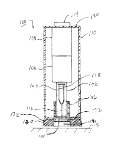
1001111 The Al 100 may conventionally comprise a drug product container
carrier 102, a
container or syringe 104 pre-filled with a fluid-based drug product, a drive
unit 106, an
activation and drive control unit 108, a housing 110 for enclosing one or more
of the drug
product container carrier 102, the container 104, the drive unit 106, and the
activation and
drive control unit 108. The All00 may also comprise a needle shield or guard
112
disposed within (as shown) or external to the housing 110. The container or
syringe 104
may include an injection needle 116 and a stopper 118 for dispensing the drug
product.
The container carrier 102 may be configured to receive and hold the container
104 in
defined relationship to the housing 110 and be axially movable in relation to
the housing
110, for needle penetration purposes, between a rear position and a front
position,
movement between which positions is used for needle penetration. The housing
110 of
the Al 100 may have a first or rear end wall 120 and an opposing second or
front end
wall 122, which respectively define activation and injection ends of the AT
100. The
16
CA 02888788 2015-04-17
WO 2014/063123
PCT/US2013/065798
front end wall 122 may have an injection needle opening 124 that allows the
injection
needle 116 of the container or syringe 104 to extend therethrough during the
operation of
the Al 100, as illustrated in FIG. 1B. The drive unit 106 may include an
autopenetration
mechanism for moving the carrier 102 or container 104 relative to the housing
110 or
carrier 102, respectively to insert the injection needle 116 into the skin S.
The drive unit
106 may further include an autoinjection mechanism for moving or plunging the
stopper
118 through the container or syringe 104 to dispense the drug product, and a
needle
shield deployment mechanism for deploying the needle shield 112 around the
injection
needle 116 after completion of the injection. If the Al 100 is not provided
with the
optional needle shield 112, the autopenetration mechanism may also be
configured to
automatically withdraw the injection needle 116 back into the housing 110. The
various
drive unit mechanisms may utilize stored energy in any known form including,
without
limitation, electrical, mechanical (e.g., elastic member such as springs), gas
pressure, gas
releasing, and any combination thereof. The stored energy can be transmitted
by
corresponding conventional transmission mechanisms, e.g. electromechanical,
such as
electric motors or solenoids, hydraulic, pneumatic, mechanical springs, gears,
rods, and
the like. The drive control and activation unit may be provided for activating
and
sequencing the drive mechanisms of the drive unit 106 and may comprise any
well know
type of a releasable lock arrangements, electronic controllers, combinations
thereof, and
the like. The activation and drive control unit 108 may be both armed and
injection
initiated by a button or switch 114 extending though the rear end wall 120 of
the housing
110 at the activation end of the Al 100. In other embodiments, the needle
shield 112 may
extend slightly past the front end wall 122 of the AT housing 110 and be
adapted to
17
CA 02888788 2015-04-17
WO 2014/063123
PCT/US2013/065798
operate as a trigger to arm the activation and drive control unit 108 when the
needle
shield 112 is depressed by contact with the skin. In such other embodiments,
depression
of the activation button 114 would cause the activation and drive control unit
108 to
initiate delivery.
[00112] The SMF 130 extends the surface area of the injection end (front wall
122) of
the Al 100, which comes in contact with the skin S of the injection site
during initial
activation and/or unlocking. As the user presses downward to aiiii the Al 100,
the SMF
130gently stretches the skin S taut, and out of the way from the center of the
injection site
and injection needle 116 of the Al 100.
[00113] As collectively illustrated in FIGS. 2A, 2B, 3A, and 3B, the SMF 130,
230 may
comprise a flexible, annular body 132, 232 having a first end surface 134,
234, an
opposing second end surface 136, 236, a cylindrical side surface 138, 238
extending
between the first end surface 134, 234 and the second end surface 136, 236,
and an
aperture 140, 240 extending through a generally central portion of the body
132, 232.
Certain embodiments of the SMF 130, 132 may optionally include protrusions
142, 242
disposed on the first surface 134, 234 thereof, the purpose of which will be
explained
further on. In some embodiments, the SMF 130, 230 may be made from a flexible
material, such as transparent polyurethane or silicone-polyurethane co-
polymer, which
allows the user to view the injection needle 116 through the SMF 130, 230
during an
injection. In other embodiments, the SMF 130, 230 may be made from a
translucent or an
opaque polyurethane material, a nitrile rubber copolymer material, or any
other suitable
material capable of flexing. As shown in the embodiment illustrated in FIGS.
2A and 2B,
the side surface 138 of the SMF 130 may be constructed to flare outwardly from
the first
18
CA 02888788 2015-04-17
WO 2014/063123
PCT/US2013/065798
surface 134 to the second surface 136 to allow the SMF 130 to be easily
compressed and
flattened, as illustrated in FIG .1B, by pressing the Al 100 down on the skin
S at the
injection site thereby maximizing radial expansion of the SMF 130,
particularly the
second surface 136 thereof. As illustrated, in FIGS. IA and 1B, the aperture
140 of the
SMF 132 axially aligns with the injection needle opening 124 formed in the
front end
wall 122 of the Al housing 110 to allow the injection needle 116 of the
container or
syringe 104 to extend therethrough during the operation of the Al 100.
[00114] In certain embodiments, the SMF may be a separate accessory that a
user can
removably attach to AT at injection time. In such embodiments, the SMF may be
selected
from a kit of differently configured SMFs. The kit may be provided with the Al
or be
available separately for use with the AT. For example but not limitation, one
or more of
the SMFs may be configured to spread or stretch the skin taut at the injection
site while
one or more of the other SMFs may be configured to pinch the skin at the
injection site.
Accordingly, the user can select a desired one of the SMFs in the kit based on
whether
the user wants a skin pinching or skin spreading effect. In some embodiments,
the SMF
may be configured to both spread/stretch the skin or pinch the skin at the
injection site,
depending upon whether the user is pressing the AT down or lifting it up.
1001151 Any suitable coupling arrangement may removably attach the SMF to the
Al
100. FIGS. 4A-4C illustrate an embodiment of a twist locking arrangement that
may be
used for removably attaching the SMF 130, 230 illustrated in FIGS. 2A-2B and
FIGS.
3A-3B, to the Al 100. The twist locking arrangement may comprise two or more
arcuate
slots 126 formed in the front end wall 122 of the Al 100 in, for example, a
circularly
spaced arrangement. The twist locking arrangement may further comprise a
19
CA 02888788 2015-04-17
WO 2014/063123
PCT/US2013/065798
corresponding number of protrusions 142, 242 formed on the first surface 134,
234 of the
SMF 130, 230 in, for example, a circularly spaced arrangement. The protrusions
142,
242 of the SMF 130, 230 are configured to slidably move within the arcuate
slots 126
formed in the front end wall 122 of the Al 100. Although not illustrated, the
two or more
arcuate slots may be formed in the first end surface of the SW and the
corresponding
number of protrusions may be formed on the front end wall of the AL The
protrusions
142, 242 may have a pin-head configuration or have any other suitable
configuration
capable of being removably retained in the arcuate slots. One end 128 of each
of the
arcuate slots 126 may be enlarged for allowing insertion and withdrawal of the
pin-head
shaped protrusions 142, 242. To attach the SMF 130, 230 to the injection end
of the AT
100, the user may insert the protrusions 142, 242 into the enlarged ends 128
of the
arcuate slots 126 and twist the SMF 130, 230 in a first direction relative to
the Al 100 to
lock the SMF 130, 230 on the Al 100. The SMF 130, 230 may be removed from the
Al
100 by twisting the SMF 130, 230 relative to the Al 100 in a second direction
and then
separating the SMP 130, 230 from the Al 100.
1001161 FIGS. 4D-4F illustrate another embodiment of a coupling arrangement
that may
removably attach the SMF 130, 230 to the Al 100. The coupling arrangement
comprises
an adaptor collar 260, which slides onto the injection end of the Al housing
110 and
allows a snap-lock attachment of interchangeable SMFs 130, 230 to the Al 100.
The
adaptor collar 260 may include a metal sleeve 270 for affixing the adaptor
collar 260 to
the AT housing 110. The metal sleeve may comprise two or more spaced apart
barb-like
gripping elements 274 formed on an inner surface 272 of the metal sleeve 270.
The metal
sleeve 270 may be installed in the adaptor collar 260 on an inner surface 266
thereof
CA 02888788 2015-04-17
WO 2014/063123
PCT/US2013/065798
adjacent to a first open end 262 of the collar 260. The metal sleeve 270 is
sized to
friction-fit against the inner surface 266 of the adaptor collar 260 so that
it will not pull
out of the collar 260 when unsnapping an SMF 130, 230 from the collar 260 or
snapping
an SMF 130, 230 onto the collar 260. When the adaptor collar 260 is pressed
onto the
injection end of the Al housing 110, the barb-like gripping elements 274 of
the metal
sleeve 270 may dig into and grip the Al housing 110 thereby preventing the
removal of
the adaptor collar 260 from the Al, particularly when unsnapping an SMF 130,
230 from
the collar 260. A first member 268 of a snap locking arrangement may be formed
on the
inner surface 266 of the adaptor collar 260 adjacent to a second open end 264
thereof and
a second member 276 of the snap locking arrangement may be formed on the side
surface
138, 238 of the SMF 130, 230 adjacent to the first end surface 134, 234
thereof One of
the first and second members 268, 276 of the snap fastening arrangement may
comprise a
continuous or segmented bead (e.g., first member 268 illustrated in FIGS. 4D-
4F) and the
other one of the first and second members 268, 276 may comprise a continuous
or
segmented groove (e.g., second member 276 illustrated in FIGS. 4D-4F) adapted
to
removably receive the bead in a snap-fit manner. The snap locking arrangement
allows
users with hand-strength/dexterity issues to easily attach and remove a
desired SMF 130,
230.
[00117] In further embodiments, the SMF 130, 230 may be integrated into or
permanently attached to the Al 100 during manufacturing. In some of these
embodiments, integration or permanent attachment of the SMF 130, 230 may be
facilitated by bonding the first end surface 134, 234 of the SMF 130, 230 to
the front end
wall 122 of the Al housing 110 with a layer or film 150, 250 of adhesive, as
illustrated in
21
CA 02888788 2015-04-17
WO 2014/063123
PCT/US2013/065798
FIGS. 5A and 5B. In other embodiments, integration or permanent attachment may
be
facilitated by bonding the first end surface 134, 234 of the SMF 130, 230 to
the bottom
edge surface 113 of the needle shield 112 with a layer or film 152, 252 of
adhesive, as
illustrated in FIGS. 6A and 6B.
[00118] Referring now to FIGS. 7A-7C, the second end surface 134, 234 of the
SMF
130, 230 can be provided with features, which aid in spreading or stretching
the skin S at
the injection site taut under the SMF 130, 230, as the SMF 130, 230 is pressed
down to
radially expand the SNIT 130, 230. For example, in some embodiments, the
second
surface 134 of the SMP 130 (FIGS. 2A and 2B) may be provided with one or more
ring-
shape protrusions or ridges 244, as illustrated in FIG. 7A, or with a circle
of spaced apart
protuberances or nubs 148, as illustrated in FIG. 7B, which are selectively
positioned to
hold, stretch, and stabilize the skin S under the SMF 130, as the SMF 130
compresses,
flattens, and radially expands in response to the Al 100 being pressed down
into the skin
S at the injection site. When the Al 100 is lifted off of the skin S, the SMF
130 returns to
its original uncompressed and unflattened shape, thereby releasing the skin S.
[00119] If pinching of the skin S is desired, the ring-shape protrusions or
ridges of the
SMF 130 illustrated in FIG. 7A can also be used to raise the skin S into the
SMF 130 to
simulate pinching the skin, by lifting up slightly on the Al 100 after
compressing and
flattening the SMF 130.
[00120] In some embodiments, the second end surface 236 of the SMF 230 (FIGS.
3A
and 3B) may be provided with a sticky or grippy texture, as illustrated in
FIG. 7C, which
holds, stretches and stabilizes the skin under the SMF, as the SMF compresses,
flattens,
and radially expands in response to the Al 100 being pressed down into the
skin at the
22
CA 02888788 2015-04-17
WO 2014/063123
PCT/US2013/065798
injection site. When the Al 100 is lifted off of the skin, the SMF returns to
its original
shape and releases the skin. If pinching of the skin S is desired, the stick
or grippy texture
provided on the second end surface 236 of the SMF 230 can also be used to
raise the skin
S to simulate pinching the skin by lifting up slightly on the Al 100 after
compressing and
flattening the SMF 230.
[00121] FIG. 8A illustrates an embodiment of a palm button 330 device for easy
arming
and needle injection initiation of an Al. The palm button device 330 generally
comprises
a palm button 331 and a mounting arrangement 340 for affixing the palm button
device
330 to an AT. The palm button device 330 provides better Al stability and easy
activation
with palm operation than with finger operation, and allows one handed
operation of the
AT. Further, the palm button device 330 makes it easier to train a user to
handle and use
the Al.
[00122] Referring now to FIGS. 8A-8C, the palm button 331 of the device 330
may have
a flat bottom surface 332 and a curved top surface 334. The curved top surface
334 may
be sized to accommodate the inner surface or palm of the user's hand so that
the palm
button 331 naturally conforms to the majority of hand profiles. In some
embodiments,
the palm button 331 may be 6.0 cm long, 4.5 cm wide, and 3.5 cm tall. In other
embodiments the palm button 331 may have other dimensions. The curved top
surface
334 provides an ergonomic actuation surface for the palm button 331 so that
the user can
arm and initiate the needle injection cycle of an Al with a palm-push motion.
In some
embodiments, the curved top surface 334 of the palm button 331 may have a
mushroom-
shape or hemispherical-shape, to maximize gripping and easy pressing of the
palm button
331.
23
CA 02888788 2015-04-17
WO 2014/063123
PCT/US2013/065798
[001231 The mounting arrangement 340 may comprise a base 342 extending from a
generally central portion of the bottom surface 332 of the palm button 331 and
an adaptor
350 movably or telescopically disposed within the base 342. The mounting
arrangement
340 mechanically and operatively couples the palm button device 330 to an Al
300 (FIG.
8C). More specifically, the base 342 of the mounting arrangement 340
operatively
couples the palm button 330 of the device 330 to the activation button 314 of
the Al 300
and mechanically couples the palm button 330 to the adaptor 350. The adaptor
350, in
turn, is constructed to be pressed onto the activation end 320 of the Al
housing 310, to
mechanically couple the palm button device 330 to the Al 300. The base 342 of
the
mounting arrangement 340 may comprise a top wall 344 and a cylindrical side
wall 346
that depends from the periphery of the top wall 344. A biasing element 348,
such as a
coil spring, may extend down from the top wall 344 of the base 342. The
adaptor 350 of
the mounting arrangement 340 may comprise a top wall 352 and a cylindrical
side wall
354 that depends from the periphery of the top wall 352. The top wall 352 may
include
an opening 356 to allow the activation button 314 of the Al 300 to extend
therethrough.
The adaptor 350 may further include a metal sleeve 360 comprising two or more
spaced
apart barb-like gripping elements 36 projecting from an inner surface 362 of
the metal
sleeve 360. The metal sleeve 360 may be disposed on an inner surface 358 of
the adaptor
side wall 354 in a friction-fit manner so that the metal sleeve 360 will not
pull out of the
adaptor 350 when operating the Al 300. When the adaptor 350 is slidably placed
onto the
activation end of the AT housing 310, the barb-like gripping elements 364 of
the metal
sleeve 360 may dig into and grip the Al housing 310, thereby preventing the
removal of
the palm button device 330 from the Al 300. When the user presses the palm
button 331
24
CA 02888788 2015-04-17
WO 2014/063123
PCT/US2013/065798
down to arm and initiate the injection cycle of the Al 330, the biasing
element 348
presses the activation button 314 of the Al 300 down and becomes compressed
between
the top wall 344 of the base 342 and the activation button of the Al 300. When
the user
releases the palm button 331, the compressed biasing element 348 returns the
palm button
331 to the undepressed position and allows the activation button 314 of the Al
330 to
return the undepressed position.
[00124] As best illustrated in FIG. 8B, a detent arrangement 370 may be
provided for
preventing the base 342 from being removed from the adaptor 350 when the palm
button
331 is in an undepressed state, and for allowing the base 342 to move down
relative to the
adaptor 350 when the palm button 331 is depressed. A first member 372 of the
detent
arrangement may be foi tiled on an inner surface 347 of the base 342 and a
second
member 374 of the detent arrangement may be formed on an outer surface 355 of
the
adaptor 350. One of the first and second members 372, 374 of the detent
arrangement
may comprise a continuous or segmented, downward facing, wedge-shaped
projection
(e.g., first member 372 illustrated in FIGS. 8A-8C) and the other one of the
first and
second members 372, 374 may comprise a continuous or segmented, downward
facing
wedge-shaped recess (e.g., second member 374 illustrated in FIGS. 8A-8C),
which is
adapted to receive the wedge-shaped projection 372.
[00125] The palm button device 330 may be made of a plastic material or any
other
suitable material including metal, hard rubber, and fiberglass. A soft, grippy
coating 336
may be disposed over the top surface 334 of the palm button 331 to provide the
palm
button 331 with a softer feel and grip. Coating 336 may be a polyurethane gel
elastomer
layer or silicone-polyurethane copolymer layer.
CA 02888788 2015-04-17
WO 2014/063123
PCT/US2013/065798
[001261 In some embodiments, the palm button 331 of the palm button device 330
may
be integrated into the Al during manufacturing instead of being adapted for
installation
onto existing AIs. For example, in some embodiments, the palm button 330 may
be
adapted to replace the conventional activation button of the AT, as
illustrated in FIG. 8D.
1001271 FIGS. 9A and 9B illustrate another embodiment of the palm button
device 430
where like elements are identified by like reference numerals. The palm button
device
430 is similar to the palm button device 330 illustrated in FIGS. 8A-8C except
for the
structure of palm button 431, which has an elongated shape formed by top and
bottom
walls 432 and 434, respectively, which are connected by side walls 438, and
end walls
440. Accordingly, the palm button 431 and the mounting arrangement 340 define
a T-
shaped handle structure. .A polyurethane gel elastomer layer 436 may be
disposed over
the top wall 432 of the palm button 431 to provide the palm button 431 with a
softer feel
and grip. In some embodiments, the palm button 431 may be 10.0 cm long, 4.0 cm
wide,
and 2.0 cm tall, although other embodiments of the palm button 431 may have
other
dimensions. In some embodiments, the palm button 431 may have indented side
areas
442 (best illustrated in FIG. 9B) for receiving the user's thumb so that the
user can more
easily grasp or grip the palm button 431. In addition, the palm button 431 may
be
configured for both left- and right-handed use.
[001281 FIGS. l OA and 10B illustrate an embodiment of a hand holder (HH)
device 530
for use with an Al 500. The HH device 530 provides an ergonomic shape for
improved
usability given the various physical limitations of a user's diseased state.
The HH device
530 may comprise a sleeve 532 which functions as a hand grip, and one or more
hand
26
CA 02888788 2015-04-17
WO 2014/063123
PCT/US2013/065798
rests 540 pivotally connected to the sleeve 532(two opposing hand rests 540
are
illustrated in FIGS. 10A and 10B ).
[001291 The sleeve 532 may comprise a top wall 534 and a cylindrical side wall
536 that
depends from the periphery of the top wall 534. The wall 534 may include an
aperture
538 for allowing the activation button 514 of the Al 500 to extend
therethrough. The top
wall 534 of the sleeve 532 can operate as stop to correctly position the
sleeve 532 on the
Al 500 during installation thereof Once installed, the sleeve 532 of the HH
device 530
forces the user to grip the Al 500 at the proper location so that the user can
use the same
hand to comfortably hold, stabilize and press the activation button 514 of the
Al 500.
1001301 Referring now to FIGS. 10C-10F, the hand rests 540 of the HH device
530 may
be constructed as arm-like members. The hand rest arms 540 may be pivotally
attached
to the sleeve 532 by pivot pin structures. As best illustrated in FIGS. 10E
and 10F, each
pivot pin structure may include a slot 552 formed in the sleeve 532, a pair of
axially
aligned pivot pins 554, and a pair of axially aligned pivot pin receiving
apertures 556.
The slots 552 may be formed just above the open end 533 of the sleeve 532. The
pivot
pins 554 may extend from lateral edges 553 of the slots 552 and the pivot pin
receiving
apertures 556 may be formed on side surfaces 542 of the hand rest arms 540,
adjacent to
the attachment ends 544 of the hand rest arms 540. The pivot pin structure
allows the
hand rest arm 540 to be pivoted between an up position (FIG. 10A) and a down
position
(FIG. 10B). In the down position, the hand rest arms 540 extend out from and
are
generally perpendicular to the sleeve 532 and, therefore, operate to hold the
user's hand
on the Al 500 in the proper position by preventing the user's hand from
sliding down the
sleeve 532 and onto the Al 500. The hand rest arms 540 may be contoured to
receive the
27
CA 02888788 2015-04-17
WO 2014/063123
PCT/US2013/065798
hypothenar muscle area of the user's hand adjacent to the little finger
(digiti minimi).
The hand rest arms 540 may also function as clamps in the down position, to
affix the HH
device 500 to the Al 500. As best illustrated in FIGS. 10E and 10F, the hand
rest arms
540 in such embodiments can each include a projection 546 at the attachment
end 544
thereof (FIGS. 10C and 10D), which engages the housing 510 of the Al 500 when
the
hand rest arm 540 is in the down position, thus enabling the arm 540 to damp
and affix
the HH device 500 to the Al 500. Further, each of the hand rest arms 540 may
be
provided with a detent arrangement for holding hand rest arms 540 in the down
(clamping) position. The detent arrangement may comprise a projection 560
extending
from each side surface 542 of the hand rest arm 540 and a recess 562 formed in
each
lateral edge surface 553 of the slot 552. When the hand rest arm 540 is in the
up position,
as illustrated in FIG. 10E, the projections 560 of the detent arrangement
slidably engage
the lateral edge surfaces 553 of the slot 552. When the hand rest arm 540 is
pivoted
down into the clamping position, as illustrated in FIG. 10F, the projections
560 slide
along the lateral edge surfaces 553 of the slot 552 and enter the recesses 562
thereby
locking the hand rest arm 540 in the down and clamping position. The detent
arrangement can be unlocked by applying an upward force on the hand rest arm
540,
which is sufficient to withdraw the projections 560 from the recesses 562,
thereby
allowing the arm 540 to be pivoted back to the up position.
[00131] In further embodiments, an adhesive or a metal sleeve comprising
spaced apart
barb-like gripping elements similar to the metal sleeve described above with
respect to
the palm button device can be provided on the inner surface of the sleeve 532
to affix the
HH device 530 to the AT 500. The adhesive or metal sleeve can be used in
addition to the
28
CA 02888788 2015-04-17
WO 2014/063123
PCT/US2013/065798
hand rest aims 540 with the earlier described clamping structures or alone
with hand rest
arms 540 that do not have the clamping structures.
[001321 When the hand rest arms 540 are in the up position, as illustrated in
FIG. 10A,
the HH device 530 can be easily packaged. Once removed from its package, the
HH
device 530 can be installed on the Al 500. During installation, the HH device
530 may
be slidably placed over the end of the Al 500 until the activation button 514
extends
through the aperture 538 in the top wall 534 of the sleeve 532 and the top
wall 534
engages the end wall of the Al 500 which surrounds the activation button 514,
thereby
properly positioning the sleeve of the HH device on the Al. The hand rest arms
540 may
then be pivoted down from the up position to the down position where the hand
rest arms
540 may engage the Al 500 to affix the HH device 530 to the AT 500 and prevent
downward slippage of the user's hand as described earlier.
[00133] As illustrated in FIG. 10G, some embodiments of the HH device 530 may
have a
sleeve 572 with a contoured hand grip 574 that enhances the ergonomic holding
feature
of the HH device 530. The hand grip 574 may be unitary with the sleeve 572 or
applied
to the sleeve as a separate layer or oversleeve. Separate layer or oversleeve
types of hand
grips 574 may be made of a soft, polyurethane gel elastomer material, or any
other
material suitable for finger or hand gripping.
[00134] FIGS. l IA and 11B illustrate another embodiment of a hand holder (HH)
device
630 for use with an Al 600. The HH device 630 may comprise an open-ended
sleeve 632
and a fixed hand rest arrangement 640 disposed over one of the open ends of
the sleeve
632. The fixed hand rest arrangement 640 may be a unitary member that includes
a top
wall 642 and two L-shaped hand rests 644 that depend from the periphery of the
top wall
29
CA 02888788 2015-04-17
WO 2014/063123
PCT/US2013/065798
642. The bottom portion 645 of each hand rest extends out from the sleeve and
may be
contoured to receive the hypothenar muscle area of the user's hand adjacent to
the little
finger (digiti minimi). The top wall 642may include an aperture 646 for
allowing the
activation button 614 of the Al 600 to extend therethrough. As in the previous
embodiment, the top wall 642 can operate as stop to correctly position the
sleeve 632 on
the Al 600 during installation thereof. Once installed, the sleeve 632 of the
HH device
630 forces the user to grip the Al 600 at the proper location so that the user
can use the
same hand to comfortably hold, stabilize and press the activation button 614
of the AT
600. The hand rest arms hold the user's hand on the Al 600 in the proper
position by
preventing the user's hand from sliding down the sleeve 632 and onto the Al
600. The
inner surface of the sleeve 632 of the HH device 630 can be provided with a
metal sleeve
having spaced apart barb-like gripping elements similar to the metal sleeve
described
above with respect to the palm button device, to affix the HH device 630 to
the housing
610 of the Al 600. An adhesive may also be used alone or with the metal sleeve
or other
mechanical means, to affix the HH device 630 to the housing 610 of the Al 600.
1001351 The HH device may be provided as an accessory item for the AT or
integrated
into the AT. In some embodiments, the HH device may function as an extension
to the
housing of the Al once affixed or attached to the AT, thereby functioning as a
ergonomic
holding feature, as described earlier. The HH device may be utilized on
multiple types of
AIs, including AIs that have only single activation feature (e.g., a needle
shield), and AIs
that have two activation features (e.g., a needle shield and an activation
button). In some
embodiments, the activation button may be located on the side of the Al
instead of the
top or rear wall of the Al.
CA 02888788 2015-04-17
WO 2014/063123
PCT/US2013/065798
[001361 In other embodiments, the HH device may be constructed and adapted as
an
active component of the Al, such that once affixed, attached, or placed on the
Al, it can
operate to activate the activation button of the Al in response to the
application of a
downward force on the I-LH device which causes the sleeve of the HH device to
move
axially relative to the housing of the Al and depress the Al's activation
button. Such
embodiments will allow the user to utilize the benefit of the Al's ergonomic
design to
provide additional leverage to depress the activation button (for Ms that have
two feature
activation (e.g., a needle shield and an activation button).
[001371 In still further embodiments, the HH device may be permanently
attached to the
AT during manufacturing. In such embodiments, the HH device may be constructed
and
adapted as a single or multiple use component.
[001381 FIGS. 12A-12C illustrate an embodiment of a needle shield 712 for use
in an AT
700. The needle shield 712 may have a cylindrical shape and includes a first
edge surface
713 and a second edge surface 715 opposite to the first edge surface 713. The
needle
shield 712 may be constructed so that the second edge surface 715 contacts the
skin at the
injection site during the operation of the AT. As illustrated in FIGS. 12A and
12C, the
second edge surface of the needle shield may be configured as an enlarged,
rounded lip,
which makes contact with the user's skin more comfortable. The enlarged,
rounded lip
715 has a larger surface area than the sharp edges of conventional needle
shields, thus,
making skin contact more comfortable during the injection process. As
illustrated in FIG.
12B, the SMFs 130, 230 described earlier can be modified for use with AIs
utilizing the
needle shield of the present disclosure, by increasing the diameter of the
needle aperture
31
CA 02888788 2015-04-17
WO 2014/063123
PCT/US2013/065798
140, 240 that extends through the SMF 130, 230, to accommodate the enlarged,
round lip
715 of the needle shield.
[001391 In some embodiments, the needle shield 700 may be colored to indicate
to the
user that the injection is completed. More specifically, when the injection
cycle has been
completed and the colored needle shield 712 is subsequently deployed to cover
the
exposed injection needle, the deployed, colored needle shield 700 indicates to
the user
that the injection is completed.
1001401 The syringe or other primary container of the AT may be prefilled with
a
pharmaceutical product, such as an erythropoiesis stimulating agent (ESA),
which may
be in a liquid or a lyophilized form. An ESA can be an erythropoiesis
stimulating
protein. As used herein, "erythropoiesis stimulating protein" means any
protein that
directly or indirectly causes activation of the erythropoietin receptor, for
example, by
binding to and causing dimerization of the receptor. Erythropoiesis
stimulating proteins
comprise erythropoietin and variants, analogs, or derivatives thereof that
bind to and
activate erythropoietin receptor; antibodies that bind to erythropoietin
receptor and
activate the receptor; or peptides that bind to and activate erythropoietin
receptor.
Erythropoiesis stimulating proteins comprise, but are not limited to, epoetin
alfa, epoetin
beta, epoetin delta, epoetin omega, epoetin iota, epoetin zeta, and analogs
thereof,
pegylated erythropoietin, carbamylated erythropoietin, mimetic peptides
(comprising
EMPl/Hematide), and mimetic antibodies. Exemplary erythropoiesis stimulating
proteins comprise erythropoietin, darbepoetin, erythropoietin agonist
variants, and
peptides or antibodies that bind and activate erythropoietin receptor.
32
CA 02888788 2015-04-17
54697-3
[00141] The term erythropoiesis stimulating protein comprises without
limitation
Epogene (epoetin alfa), Aranesp (darbepoetin alfa), Dynepo (epoetin delta),
Mircera (methyoxy polyethylene glycol-epoetin beta), Hematidem
(peginesatide),
MRK-2578, INS-22, Retacrit (epoetin zeta), Neorecormon (epoetin beta),
SilapoTm
(epoetin zeta), Binocrit (epoetin alfa), epoetin alfa Hexal, AbseamedTm
(epoetin alfa),
RatioepoTm (epoetin theta), EporatioTM (epoetin theta), 13iopoinTM (epoetin
theta), epoetin
alfa, epoetin beta, epoetin zeta, epoetin theta, and epoetin delta.
1001421 The term erythropoiesis stimulating protein further comprises the
molecules or
variants or analogs as disclosed in the following patents or patent
applications:
U.S. Pat. Nos. 4,703,008; 5,441,868;
5,547,933; 5,618,698; 5,621,080; 5,756,349; 5,767,078; 5,773,569; 5,830,851;
5,856,298;
5,955,422; 5,986,047; 6,030,086; 6,310,078; 6,391,633; 6,583,272; 6,586,398;
6,900,292;
6,750,369; 7,030,226; 7,084,245; and 7,271,689; U.S. Publ. Nos. 2002/0155998;
2003/0077753; 2003/0082749; 2003/0143202; 2003/0215444; 2004/0009902;
= 2004/0071694; 2004/0091961; 2004/0143857; 2004/0157293; 2004/0175379;
2004/0175824; 2004/0229318; 2004/0248815; 2004/0266690; 2005/0019914;
2005/0026834; 2005/0096461; 2005/0107297; 2005/0107591; 2005/0124045;
2005/0124564; 2005/0137329; 2005/0142642; 2005/0143292; 2005/0153879;
2005/0158822; 2005/0158832; 2005/0170457; 2005/01813.59; 2005/0181482;
= 2005/0192211; 2005/0202538; 2005/0227289; 2005/0244409; 2006/0040858;
2006/0088906; and 2006/0111279; and PCT Publ. Nos. WO 91/05867; WO 95/05465;
WO 96/40772; WO 99/66054; WO 00/24893; WO 01/81405; WO 00/61637; WO
01/36489; WO 02/014356; WO 02/19963; WO 02/20034; WO 02/49673; WO
33
CA 02888788 2015-04-17
WO 2014/063123
PCT/US2013/065798
02/085940; WO 03/029291; WO 2003/055526; WO 2003/084477; WO 2003/094858;
WO 2004/002417; WO 2004/002424; WO 2004/009627; WO 2004/024761; WO
2004/033651; WO 2004/035603; WO 2004/043382; WO 2004/101600; WO
2004/101606; WO 2004/101611; W02004/106373; WO 2004/018667; WO
2005/001025; WO 2005/001136; WO 2005/021579; WO 2005/025606; WO
2005/032460; WO 2005/051327; WO 2005/063808; WO 2005/063809; WO
2005/070451; 'WO 2005/081687; WO 2005/084711; WO 2005/103076; WO
2005/100403; WO 2005/092369; WO 2006/50959; WO 2006/02646; WO 2006/29094;
and WO 2007/136752.
1001431 Alternatively, the syringe or other primary container of the Al may
also be
prefilled with other products. Examples of other pharmaceutical products that
may be
used may comprise, but are not limited to, therapeutics such as a biological
(e.g., Enbrelt
(etanercept, TNF-receptor /Fc fusion protein, TNF blocker), anti-TNF
antibodies such as
adalimumab, infliximab, certolizumab pegol, and golimumab; anti-IL-12
antibodies such
as ustekinumab, other Fe fusions such as CTL4A:Fc also known as abacept;
Neulastak
(pegylatcd filgastrim, pcgylatcd G-CSF, pcgylated hu-met-G-CSF), Neupogeng
(filgrastim , G-CSF, hu-met-G-CSF), Nplatek (romiplostim), Vectibix
(panitumumab),
Sensipark (cinacalcet), and Xgeva and Prolia (each denosamab, AMG 162); as
well
as other small molecule drugs, a therapeutic antibodies, a polypeptides,
proteins or other
chemicals, such as an iron (e.g., ferumoxytol, iron dextrans, ferric
glyconate, and iron
sucrose). The therapeutic may be in liquid form, or reconstituted from
lyophilized form.
[00144] Among particular illustrative proteins that can be used in the syringe
or other
primary container of the Al are antibodies, peptibodies, pegylated proteins,
polypeptides,
34
CA 02888788 2015-04-17
54697-3
and related proteins (comprising fusions, fragments, analogs, variants or
derivatives
thereof) for example, proteins that specifically .bind to: OPGL; IL-4
receptor; interleukin
1-receptor 1 ("IL1-R1"); angiopoietin-2 (Ang2); NGF; CD22; IGF-1; B-7 related
protein
1 (B7RP1); IL-15; IL-17 Receptor A: IFN gamma; TALL-1; parathyroid hormone
("PTH"); thrombopoietin receptor ("TPO-R"); hepatocyte growth factor ("HGF");
TRAIL-R2; Activin= A; TGF-beta; amyloid-beta; c-Kit; a4(37: and IL-23 or one
of its
subunits; and other therapeutic proteins.
[00145] The syringe or other primary container of the Al may also be
prefilled.with =
OPGL specific antibodies, peptibodies, and related proteins, and the like
(also referred to
as RANKL specific antibodies, peptibodies and the like), comprising fully
humanized
and human OPGL specific antibodies, particularly fully humanized monoclonal
antibodies, comprising but not limited to the antibodies described in PCT
Publ. No. WO
03/002713, as to OPGL specific antibodies
and antibody related proteins, particularly those having the sequences set
forth therein,
particularly, but not limited to, those denoted therein: 9H7; 18B2; 2D8; 2E11;
16E1; and
22B3, comprising the OPGL specific antibodies having either the light chain of
SEQ ID
NO: 2 therein as set forth in Figure 2 therein and/or the heavy chain of SEQ
ID NO:4
=
therein, as set forth in Figure 4 therein.
[00146] The syringe or other primary container of the Al may also be prefilled
with
inyostatin binding proteins, peptibodies, and related proteins, and the like,
comprising
myostatin specific peptibodies, particularly those described in US Publ. No.
=
CA 02888788 2015-04-17
54697-3 =
2004/0181033 and PCT Pub!. No. WO 2004/058988,
particularly in parts pertinent to myostatin specific peptibodies,
comprising but not limited to peptibodies of the mTN8-19 family, comprising
those of
SEQ ID NOS: 305-351, comprising TN8-19-1 through TN8-19-40, TN8-19 coal and
TN8-19 con2; peptibodies of the inL2 family of SEQ ID NOS: 357-383 therein;
the
mL15 family of SEQ ID NOS: 384-409; the inL17 family of SEQ ID NOS: 410-438
therein; the mL20 family of SEQ ID NOS: 439-446 therein; the mL21 family of
SEQ ID
NOS: 447-452 therein; the inL24 family of SEQ ID NOS: 453-454 therein; and
those of
SEQ ID NOS: 615-631 therein,
[00147] The syringe or other primary container.of the Al may also be prefilled
with IL-4
receptor specific antibodies, peptibodies, and related proteins, and the like,
particularly
those that inhibit activities mediated by binding of IL-4 and/or IL-13 to the
receptor,
comprising those described in PCT Publ. No. WO 2005/047331 or PCT Appl. No.
PCT/US2004/03742 and in US Publ. No. 2005/112694,
particularly in parts pertinent to IL-4 receptor specific
antibodies, particularly such antibodies as are described therein,
particularly, and without
limitation, those designated therein: L1H1; L1 H2; L1H3; L IH4; L1H5; L1H6; L
1H7;
L1H8; L11-19; L1H10; LI1111; L2H1; L2H2; L2I-13; L2H4; L2H5; L2H6; L2H7; L2H8;
L2H9; L2H10; L2H11; L2H12; L2H13; L2H14; L3111; L4H1; L5H1; L6H1.
36
CA 02888788 2015-04-17
54697-3
1001481 The syringe or other primary container of the Al may also be prefilled
with IL1-
RI specific antibodies, peptibodies, and related proteins, and the like,
comprising but not
limited to those described in U.S. Pub!. No. 2004/097712A1,
in parts pertinent to ILI-R1 specific. binding proteins,
monoclonal antibodies in particular, especially, without limitation, those
designated
therein: 15CA, 26F5, 27F2, 24E12, and 10H7.
[00149] The syringe or other primary container of the AT may also be prefilled
with
Ang2 specific antibodies, peptibodies, and related proteins, and the like,
comprising but
not limited to those described in PCT Publ. No. WO 03/057134 and U.S. Publ No.
2003/0229023,
in parts pertinent to Ang2 specific antibodies and peptibodies and the like,
especially those of sequences described therein and comprising but not limited
to:
L I (N); L I (N) WT; L I (N) 1K WT; 2xL1(N); 2xLI(N) WT; Con4 (N), Con4 (N) 1K
WT,
2xCon4 (N) 1K; L IC; Ll C 1K; 2xL1C; Con4C; Con4C IK; 2xCon4C 1K; Con4-L I
(N);
Con4-L IC; TN-12-9 (N); C17 (N); TN8-8(N); TN8-14 (N); Con 1(N), also
comprising
anti-Ang 2 antibodies and formulations such as those described in PCT Publ.
No. WO
2003/030833,
particularly Ab526; Ab528; Ab53 1; Ab533; Ab535; Ab536; Ab537; Ab540; Ab543;
Ab544; Ab545; Ab546; A551; Ab553; Ab555; Ab558; Ab559; Ab565; AbFlAbFD;
AbFE; AbFJ; AbFK; AbG1D4; AbGC1E8; AbH1C12; AblAl; AblF; AbIK, AblP; and
AblP, in their various permutations as described therein.
37
CA 02888788 2015-04-17
=
54697-3
[00150) The syringe or other primary container of the Al may also be prefilled
with NGF
specific antibodies, peptibodies, and related proteins, and the like
comprising, in
particular, but not limited to those described in US Pub!. No. 2005/0074821
and US
Patent No. 6,919,426,
particularly as to NGF-specific antibodies and related proteins in this
regard, comprising
in particular, but not limited to, the NGF-specific antibodies therein
designated 4D4,
4G6, 6H9, 7H2, 14D10 and 14D11.
[00151] The syringe or other primary container of the Al may also be prefilled
with
CD22 specific antibodies, peptibodies, and related proteins, and the like,
such as those
described in US Patent No. 5,789,554,
as to CD22 specific antibodies and related proteins, particularly human CD22
specific antibodies, such as but not limited to humanized and fully human
antibodies,
comprising but not limited to humanized and fully human monoclonal antibodies,
particularly comprising but not limited to human CD22 specific IgG antibodies,
such as,
for instance, a dimer of a human-mouse monoclonal hLL2 gamma-chain disulfide
linked
to a human-mouse monoclonal hLL2 kappa-chain, comprising, but limited to, for
example, the human CD22 specific fully humanized antibody in Epratuzumab, CAS
registry number 501423-23-0;
38
CA 02888788 2015-04-17
54697-3
[001521 The syringe or other primary container of the Al may also be prefilled
with 1GF-
1 receptor specific antibodies, peptibodies, and related proteins, and the
like, such as
those described in PCT Pub!. No. WO 06/069202,
as to IGF-1 receptor specific antibodies and related proteins,
comprising but not limited to the IGF-I specific antibodies therein designated
L IH1,
L2H2, L3H3, L4H4, L5H5, L6H6, L7H7, L8H8, L9H9, LIOH10, Ll1H11, L I2H12,
L13H13, L14H14,LL5H15, L16H16, L17H17, L18H18, L19H19, L201420, L211121,
L22H22, L23H23, L24H24, L25H25, L26H26, L27H27, L28H28, L29H29, L30H30,
L31H31, L32H32, L33H33, L34H34, L35H35, L36H36, L37H37, L38H38, L39H39,
L40H40, L41H41, L42H42, L43H43, L44H44, L45H45, L461146, L47H47, L48H48,
L49H49, L50H50, L51H51, L52H52, and IGF-1R-binding fragments and derivatives
thereof.
[001531 Also among non-limiting examples of anti-IGF-IR antibodies for use in
the
methods and compositions of the present invention are each and all of those
described in:
(i) US Publ. No. 2006/0040358 (published February 23, 2006), 2005/0008642
(published
January 13, 2005), 2004/0228859 (published November 18, 2004), comprising but
not
limited to, for instance, antibody IA (DSMZ Deposit No. DSM ACC 2586),
antibody 8
(DSMZ Deposit No. DSM ACC 2589), antibody 23 (DSMZ Deposit No. DSM ACC
2588) and antibody 18 as described therein; (ii) PCT Publ. No. WO 06/138729
(published December 28, 2006) and WO 05/016970 (published February 24, 2005),
and
Lu et al., 2004, J Biol. Chem. 279:2856-65, comprising but not limited to
antibodies 2F8,
Al2, and IMC-Al2 as described therein; (iii) PCT Publ. No. WO 07/012614
(published
39
=
CA 02888788 2015-04-17
WO 2014/063123
PCT/US2013/065798
February 1,2007), WO 07/000328 (published January 4, 2007), WO 06/013472
(published February 9, 2006), WO 05/058967 (published June 30, 2005), and WO
03/059951 (published July 24, 2003); (iv) US Pub!. No. 2005/0084906 (published
April
21, 2005), comprising but not limited to antibody 7C10, chimaeric antibody
C7C10,
antibody h7C10, antibody 7H2M, chimaeric antibody *7C10, antibody GM 607,
humanized antibody 7C10 version 1, humanized antibody 7C10 version 2,
humanized
antibody 7C10 version 3, and antibody 7H2HM, as described therein; (v) US
Publ. Nos.
2005/0249728 (published November 10, 2005), 2005/0186203 (published August 25,
2005), 2004/0265307 (published December 30, 2004), and 2003/0235582 (published
December 25, 2003) and Maloney et al., 2003, Cancer Res. 63:5073-83,
comprising but
not limited to antibody EM164., resurfaced EM164, humanized EM164, huEM164
v1Ø,
huEM164 v1.1, huEM164 v1.2, and httEM164 v1.3 as described therein; (vi) US
Pat. No.
7,037,498 (issued May 2, 2006), US Publ. Nos. 2005/0244408 (published November
30,
2005) and 2004/0086503 (published May 6, 2004), and Cohen, et al., 2005,
Clinical
Cancer Res. 11:2063-73, e.g., antibody CP-751,871, comprising but not limited
to each
of the antibodies produced by the hybridomas having the ATCC accession numbers
PTA-
2792, PTA-2788, PTA-2790, PTA-2791, PTA-2789, PTA-2793, and antibodies 2.12.1,
2.13.2, 2.14.3, 3.1.1, 4.9.2, and 4.17.3, as described therein; (vii) US Pub!.
Nos.
2005/0136063 (published June 23, 2005) and 2004/0018191 (published January 29,
2004), comprising but not limited to antibody 19D12 and an antibody comprising
a heavy
chain encoded by a polynucleotide in plasmid 15H12/19D12 HCA (74), deposited
at the
ATCC under number PTA-5214, and a light chain encoded by a polynucleotide in
plasmid 15H12/19D12 LCF (k), deposited at the ATCC under number PTA-5220, as
CA 02888788 2015-04-17
' 54697-3
described therein; and (viii) US Publ. No. 2004/0202655 (published October 14,
2004),
comprising but not limited to antibodies PINT-6A1, PINT-7A2, PINT-7A4, PINT-
7A5,
PINT-7A6, PINT-8A1, PINT-9A2, PINT-11A1, PINT-11A2, PINT-11A3, PINT-11 A4,
PINT-11A5, PINT-11A 7, PINT-11Al2, PINT-12A I , PINT-12A2, PINT-12A3, PINT-
12A4, and PINT-12A5, as described therein;
particularly as to the aforementioned
antibodies, peptibodies, and related proteins and the like that target IGF-1
receptors.
1001541 The syringe or other primary container of the AT may also be prefilled
with B-7
related protein 1 specific antibodies, peptibodies, related proteins and the
like ("B7RP-1 ,"
also is referred to in the literature as B7H2, ICOSL, B7h, and CD275),
particularly
B7RP-specific fully human monoclonal IgG2 antibodies, particularly fully human
IgG2
monoclonal antibody that binds an epitope in the first inununoglobulin-like
domain of
B7RP-1, especially those that inhibit the interaction of B7RP-1 with its
natural receptor,
ICOS, on activated T cells in particular, especially, in all of the foregoing
regards, those
disclosed in U.S. Publ. No. 2008/0166352 and PCT Publ. No. WO 07/011941,
as to such antibodies and related
proteins, comprising but not limited to antibodies designated therein as
follow: I 6H
(having light chain variable and heavy chain variable sequences SEQ ID NO:1
and SEQ
ID NO:7 respectively therein); .5D (having light chain variable and heavy
chain variable
sequences SEQ ID NO:2 and SEQ ID NO:9 respectively therein); 2H (having light
chain
variable and heavy chain variable sequences SEQ ID NO:3 and SEQ ID NO:10
respectively therein); 43H (having light chain variable and heavy chain
variable
sequences SEQ ID NO:6 and SEQ ID NO:14 respectively therein); 41H (having
light
41
CA 02888788 2015-04-17
54697-3
chain variable and heavy chain variable sequences SEQ ID NO:5 and SEQ ID NO:13
respectively therein); and 15H (having light chain variable and heavy chain
variable
sequences SEQ ID NO:4 and SEQ ID NO:12 respectively therein),
[00155] The syringe or other primary container of the Al may also be prefilled
with IL-
15 specific antibodies, peptibodies, and related proteins, and the like, such
as, in
particular, humanized monoclonal antibodies, particularly antibodies such as
those
disclosed in U.S. Publ. Nos. 2003/0138421; 2003/023586; and 2004/0071702; and
US
Patent No. 7,153,507, as
to IL-15 specific antibodies and related proteins, comprising peptibodies,
comprising
particularly, for instance, but not limited to, HuMax IL-15 antibodies and
related
proteins, such as, for instance, 146B7.
[00156] The syringe or other primary container of the AT may also be prefilled
with
pharmaceutical compositions comprising antagonistic human monoclonal
antibodies
against human IL-17 Receptor A. The characterization, cloning, and preparation
of IL-17
Receptor A are described in USPN 6,072,033, issued June 6, 2000.
The amino acid sequence of the human IL-17RA is
shown in SEQ ID NO:10 of USPN 6,072,033 (GenBank accession number
NM 014339). Such antibodies may comprise those disclosed in WO 2008/054603,
or the antibodies claimed in USPN
7,767,206, issued August 3, 2010, and in U.S. Serial No. 11/906,094, Patent
No, 7,939,070.
42
CA 02888788 2015-04-17
54697-3
[00157] The syringe or other primary container of the AT may also be prefilled
with IFN
gamma specific antibodies, peptibodies, and related proteins and the like,
especially
human IFN gamma specific antibodies, particularly fully human anti-IFN gamma
antibodies, such as, for instance, those described in US Publ. No.
2005/0004353,
as to IFN gamma specific antibodies,
particularly, for example, the antibodies therein designated 1118; 1118*;
1119; 1121; and
1121*. The entire sequences of the heavy and light chains of each of these
antibodies, as
well as the sequences of their heavy and light chain variable regions and
complementarity
determining regions, are each individually and specifically referred to
herein as fully disclosed in the foregoing US Publication and in Thakur et
al., Mol. Immunol. 36:1107-1115 (1999). In addition, description of the
properties of
these antibodies provided in the foregoing US publication is also referred to
herein in its entirety. Specific antibodies comprise those having the heavy
chain of SEQ ID NO: 17 and the light chain of SEQ ID NO:18; those having the
heavy
chain variable region of SEQ ID NO:6 and the light chain variable region of
SEQ ID
NO:8; those having the heavy chain of SEQ ID NO:19 and the light chain of SEQ
ID
NO:20; those having the heavy chain variable region of SEQ ID NO:10 and the
light
chain variable region of SEQ ID NO:12; those having the heavy chain of SEQ ID
NO:32
and the light chain of SEQ ID NO:20; those having the heavy chain variable
region of
SEQ ID NO:30 and the light chain variable region of SEQ ID NO:12; those having
the
heavy chain sequence of SEQ ID NO:21 and the light chain sequence of SEQ ID
NO:22;
those having the heavy chain variable region of SEQ ID NO:14 and the light
chain
variable region of SEQ ID NO:16; those having the heavy chain of SEQ ID NO:21
and
43
CA 02888788 2015-04-17
54697-3
=
the light chain of SEQ ID NO:33; and those having the heavy chain variable
region of
SEQ ID NO:14 and the light chain variable region of SEQ ID NO:31, as disclosed
in the
foregoing US Publication. A specific antibody contemplated is antibody 1119 as
disclosed in foregoing US Publication and having a complete heavy chain of SEQ
ID
NO:17 as disclosed therein and having a complete light chain of SEQ ID NO:18
as
disclosed therein.
[001581 The syringe or other primary container of the Al may also be prefilled
with
TALL-1 specific antibodies, peptibodies, and related proteins, and the like,
and other
TALL specific binding proteins, such as those described in U.S. Publ. Nos.
2003/0195156 and 2006/0135431,
as to TALL-1 binding proteins, particularly the molecules of Tables 4 and 5B
therein.
[00159] The syringe or other primary container of the AT may also be prefilled
with PTH
specific antibodies, peptibodies, and related proteins, and the like, such as
those described
in US Patent No. 6,756,480,
particularly in parts pertinent to proteins that bind PTH.
[00160] The syringe or other primary container of the AT may also be prefilled
with
TPO-R specific antibodies, peptibodies, and related proteins, and the like,
such as those
described in US Patent No. 6,835,809,
particularly in parts pertinent to proteins that bind TPO-R.
[00161] The syringe or other primary container of the AT may also be prefilled
with HGF
specific antibodies, peptibodies, and related proteins, and the like,
comprising those that
44
CA 02888788 2015-04-17
54697-3
target the HGF/SF:cMet axis (HGF/SF:c-Met), such as the fully human monoclonal
antibodies that neutralize hepatocyte growth factor/scatter (HGF/SF) described
in US
Pub!. No. 2005/0118643 and PCT Pub!. No. WO 2005/017107, huL2G7 described in
US
Patent No. 7,220,410 and 0A-5d5 described in US Patent Nos. 5,686,292 and
6,468,529
and in PCT Publ. No. WO 96/38557,
particularly in parts pertinent to proteins that bind HGF.
[00162] The syringe or other primary container of the Al may also be prefilled
with
TRAIL-R2 specific antibodies, peptibodies, related proteins and the like, such
as those
described in US Patent No. 7,521,048,
particularly in parts pertinent to proteins that bind TRAIL-R2.
[00163] The syringe or other primary container of the Al may also be prefilled
with
Activin A specific antibodies, peptibodies, related proteins, and the like,
comprising but
not limited to those described in US Publ. No. 2009/0234106,
particularly in parts pertinent to proteins that
bind Activin A.
[00164] The syringe or other primary container of the Al may also be prefilled
with
TGF-beta specific antibodies, peptibodies, related proteins, and the like,
comprising but
not limited to those described in US Patent No. 6,803,453 and US Pub!. No.
2007/0110747,
particularly in parts pertinent to proteins that bind TGF-beta.
[00165] The syringe or other primary container of the Al may also be prefilled
with
amyloid-beta protein specific antibodies, peptibodies, related proteins, and
the like,
comprising but not limited to those described in PCT Publ. No. WO 2006/081171,
CA 02888788 2015-04-17
54697-3
particularly in parts pertinent to
proteins that bind amyloid-beta proteins. Otte antibody contemplated is an
antibody
having a heavy chain variable region comprising SEQ ID NO: 8 and a light chain
variable region having SEQ ID NO: 6 as disclosed in the International
Publication.
[00166] The syringe or other primary container of the AT may also be prefilled
with c-Kit
specific antibodies, peptibodies, related proteins, and the like, comprising
but not limited
to those described in Pub!. No. 2007/0253951,
particularly in parts pertinent to proteins that bind c-Kit and/or other stem
cell factor receptors.
[001671 The syringe or other primary container of the Al may also be prefilled
with
OX4OL specific antibodies, peptibodies, related proteins, and the like,
comprising but not
limited to those described in US Appl. No. 11/068,289, Patent No. 7,081,007,
particularly in parts pertinent to proteins that bind OX4OL and/or
other ligands of the 0X040 receptor.
[00168] The syringe or other primary container of the Al may also be prefilled
with other
exemplary proteins comprising but are not limited to Activase (Alteplase,
tPA);
Aranespe (Darbepoetin alfa), Epogen (Epoetin alfa, or erythropoietin);
Avonexe
(Interferon beta-la); Bexxar (Tositumomab, anti-CD22 monoclonal antibody);
Betaseron (Interferon-beta); Campath (Alemtuzumab, anti-CD52 monoclonal
antibody); Dynepo (Epoetin delta); Velcade (bortezomib); MLN0002 (anti-
ct4B7
inAb); MLN1202 (anti-CCR2 chemokine receptor mAb); Enbre1414 (etanercept, TNF-
receptor /Fc fusion protein, TNF blocker); Eprex (Epoetin alfa); Erbitux
(Cetuximab,
anti-EGFR / HER1. / c-ErbB-l); Genotropin (Somatropin, Human Growth Hormone);
46
CA 02888788 2015-04-17
WO 2014/063123
PCT/US2013/065798
Herceptin (Trastuzumab, anti-HER2/neu (erbB2) receptor mAb); Humatropet
(Somatropin, Human Growth Hormone); Humirae (Adalimumab); Insulin in Solution;
Infergent (Interferon Alfacon-1); Natrecor (nesiritide; recombinant human B-
type
natriuretic peptide (hBNP); Kinerete (Anakinra), Leukine (Sargamostim, rhuGM-
CSF); LymphoCidet (Epratuzumab, anti-CD22 mAb); Lymphostat Be (Belimumab,
anti-BlyS mAb); Metalysel (Tenecteplase, t-PA analog); Mircerae (methoxy
polyethylene glycol-epoetin beta); Mylotargt (Gemtuzumab ozogamicin); Raptiva
(efalizumab); Cimzia (certolizumab pegol, CDP 870); SolirisTM (Eculizumab);
Pexelizumab (Anti-05 Complement); MEDI-524 (Numax0); Lucentis0 (Ranibizumab);
17-1A (Edrecolomab, Panorex0); Trabiot (lerdelimumab); TheraCim hR3
(Nimotuzumab); Omnitarg (Pertuzumab, 2C4); Osidem (IDM-1); OvaRex (B43.13);
Nuvion (visilizumab); Cantuzumab mertansine (huC242-DM I); NeoRecormon
(Epoetin beta); Neumega (Oprelvekin, Human Interleukin-11); Neulasta
(Pegylated
filgastrim, pegylated G-CSF, pegylated hu-Met-G-CSF); Neupogene (Filgrastim ,
G-
CSF, hu-MetG-CSF); Orthoclone OKT3 (Muromonab-CD3, anti-CD3 monoclonal
antibody), Procrit (Epoetin alfa); Remicadc (Infliximab, anti-TNFa
monoclonal
antibody), Reopro0 (Abciximab, anti-GP 11b/Ilia receptor monoclonal antibody),
Actemra (anti-IL6 Receptor mAb), Avastint (Bevacizumab), HuMax-CD4
(zanolimumab), Rituxan (Rituximab, anti-CD20 mAb); Tarceva (Erlotinib);
Roferon-
AE-(Interferon alfa-2a); Simulect (Basiliximab); Prexigeg (lumiracoxib);
Synagis
(Palivizumab); 146B7-CHO (anti-IL15 antibody, see US Patent No. 7,153,507),
Tysabri (Natalizumab, anti-a4integrin mAb); Valortime (MDX-1303, anti-B.
anthracis
Protective Antigen mAb); ABthraxTM; Vectibix (Panitumumab); Xolair
47
CA 02888788 2015-04-17
WO 2014/063123
PCT/US2013/065798
(Omalizumab), ETI211 (anti-MRSA mAb), IL-1 Trap (the Fe portion of human IaG1
and
the extracellular domains of both IL-1 receptor components (the Type I
receptor and
receptor accessory protein)), VEGF Trap (Ig domains of VEGFR1 fused to IgG1
Fe),
Zenapax (Daclizumab); Zenapax (Daclizumab, anti-IL-2Ra mAb), Zevalint
(Ibritumomab tiuxetan), Zetia (ezetimibe), Atacicept (TACI-Ig), anti-CD80
monoclonal
antibody (mAb) (galiximab), anti-CD23 inAb (lumiliximab), BR2-Fc (huBR3 / huFc
fusion protein, soluble BAFF antagonist); CNTO 148 (Golimumab, anti-TNFa mAb);
HGS-ETR1 (Mapatinnumab; human anti-TRAIL Receptor-1 mAb); HuMax-CD20
(Ocrelizumab, anti-CD20 human mAb); HuMax-EGFR (zaluturnumab); M200
(Volociximab, anti-a5131 integrin mAb); MDX-010 (ipilimumab, anti-CTLA-4 mAb
and
VEGFR-1 (IMC-18F1); anti-BR3 mAb; anti-C. difticile Toxin A and Toxin B C mAbs
MDX-066 (CDA-1) and MDX-1388); anti-CD22 dsFv-PE38 conjugates (CAT-3888 and
CAT-8015); anti-CD25 mAb (HuMax-TAC); anti-CD3 mAb (NI-0401); adecatumumab;
anti-CD30 mAb (MDX-060); MDX-1333 (anti-IFNAR); anti-CD38 mAb (HuMax
CD38); anti-CD4OL mAb; anti-Cripto mAb; anti-CTGF Idiopathic Pulmonary
Fibrosis
Phase I Fibrogen (FG-3019); anti-CTLA4 mAb: anti-cotaxin1 mAb (CAT-213); anti-
FGF8 mAb; anti-ganglioside GD2 mAb; anti-ganalioside GM2 mAb; anti-GDF-8 human
mAb (MY0-029); anti-GM-CSF Receptor mAb (CAM-3001); anti-HepC mAb (HuMax
HepC); anti-IFNa mAb (MEDI-545, MDX-1103); anti-IGF I R mAb; anti-IGF-1R mAb
(HuMax-Inflam); anti-IL12 mAb (ABT-874); anti-IL12/1L23 mAb (CNTO 1275); anti-
IL13 mAb (CAT-354); anti-IL2Ra mAb (HuMax-TAC); anti-IL5 Receptor mAb; anti-
integrin receptors mAb (MDX-018, CNTO 95); anti-IP10 Ulcerative Colitis mAb
(MDX-
1100); anti-LLY antibody; BMS-66513; anti-Mannose Receptor/hCGI3 mAb (MDX-
48
CA 02888788 2015-04-17
WO 2014/063123
PCT/US2013/065798
1307); anti-mesothelin dsFv-PE38 conjugate (CAT-5001); anti-PD ImAb (MDX-1106
(ONO-4538)); anti-PDGFRa antibody (IMC-3G3); anti-TGFB mAb (GC-1008); anti-
TRAIL Receptor-2 human mAb (FIGS-ETR2); anti-TWEAK mAb; anti-VEGFR/Flt-1
mAb; anti-ZP3 mAb (HuMax-ZP3); NVS Antibody #1; and NVS Antibody #2; a
sclerostin antibody, such as but not limited to romosozumab, blosozumab, or
BPS 804
(Novartis). Also included can be therapeutics such as rilotutnumab, bixalomer,
trebananib, ganitumab, conatumumab, motesanib diphosphate, brodalumab,
vidupiprant,
panitumumab, denosumab, NPLATE, PROLIA, VECTIBIX or XGEVA. Additionally,
included in the AT can be a monoclonal antibody (IgG) that binds human
Proprotein
Convertase Subtilisin/Kexin Type 9 (PCSK9), e.g. US 8,030,547, US13/469,032,
NV02008/057457, W02008/057458, W02008/057459, W02008/063382,
W02008/133647, W02009/100297, W02009/100318, W02011/037791,
W02011/053759, W02011/053783, W02008/125623, W02011/072263,
NV02009/055783, W02012/0544438, W02010/029513, W02011/111007,
NV02010/077854, W02012/088313, W02012/101251,
W02012/101252,W02012/101253, W02012/109530, and W02001/031007.
[00169] The syringe or other primary container of the Al may also be prefilled
with
antibodies comprising, but not limited to, those that recognize any one or a
combination
of proteins comprising, but not limited to, the above-mentioned proteins
and/or the
following antigens: CD2, CD3, CD4, CD8, CD' la, CD14, CD18, CD20, CD22, CD23,
CD25, CD33, CD40, CD44, CD52, CD80 (B7.1), CD86 (B7.2), CD147, IL-la, IL-1B,
IL-2, IL-3, IL-7, IL-4, IL-5, IL-8, IL-10, IL-2 receptor, IL-4 receptor, IL-6
receptor, IL-
13 receptor, IL-18 receptor subunits, FGL2, PDGF-fl and analogs thereof (see
US Patent
49
CA 02888788 2015-04-17
WO 2014/063123
PCT/US2013/065798
Nos. 5,272,064 and 5,149,792), VEGF, TGF, TGF-132, TGF-131, EGF receptor (see
US
Patent No. 6,235,883) VEGF receptor, hepatocyte growth factor, osteoprotegerin
ligand,
interferon gamma, B lymphocyte stimulator (BlyS, also known as BAFF, THANK,
TALL-I, and zTNF4: see Do and Chen-Kiang (2002), Cytokine Growth Factor Rev.
13(1): 19-25), C5 complement, IgE, tumor antigen CA125, tumor antigen MUC1,
PEM
antigen, LCG (which is a gene product that is expressed in association with
lung cancer),
HER-2, a tumor-associated glycoprotein TAG-72, the SK-I antigen, tumor-
associated
epitopes that are present in elevated levels in the sera of patients with
colon and/or
pancreatic cancer, cancer-associated epitopes or proteins expressed on breast,
colon,
squamous cell, prostate, pancreatic, lung, and/or kidney cancer cells and/or
on melanoma,
gliomaõ or neuroblastoma cells, the necrotic core of a tumor, integrin alpha 4
beta 7, the
integrin VLA-4, B2 integrins, TRAIL receptors 1, 2, 3, and 4, RANK, RANK
ligand,
TNF-a, the adhesion molecule VAP-1, epithelial cell adhesion molecule (EpCAM),
intercellular adhesion molecule-3 (ICAM-3), leukointegrin adhesin, the
platelet
glycoprotein gp IIb/IIIa, cardiac myosin heavy chain_ parathyroid hormone,
rNAPc2
(which is an inhibitor of factor Vlia-tissue factor), IYIHC I,
careinoembryonic antigen
(CEA), alpha-fetoprotein (AFP), tumor necrosis factor (TNF), CTLA-4 (which is
a
cytotoxic T lymphocyte-associated antigen), Fc-7-I receptor, HLA-DR 10 beta,
HLA-DR
antigen, L-selectin, Respiratory Syncitial Virus, human immunodeficiency virus
(HIV),
hepatitis B virus (HBV), Streptococcus mutans, and Staphlycoccus aureus.
[00170] Additional examples of known antibodies that may be contained in the
syringe
or other primary container of the AT can comprise but are not limited to
adalimumab,
bevacizumab, infliximab, abciximab, alemtuzumab, bapineuzumab,
CA 02888788 2015-04-17
WO 2014/063123
PCT/US2013/065798
belimumab, briakinumab, canakinumab, certolizumab pegol, cetuximab,
conatumumab,
denosumab, eculizumab, gemtuzumab ozogamicin, golimumab, ibritumomab
titixetan,
labetuzumab, mapatumumab, matuzumab, mepolizumab, motavizumab, muromonab-
CD3, natalizumab, nimotuzumab, ofatumumab, omalizumab, oregovomab,
palivizumab,
panitumumab, pemtumomab, pertuzumab, ranibizumab, rituximab, rovelizumab,
tocilizumab, tositumomab, trastuzumab, ustekinumab, zalutumumab, and
zanolimumab.
[00171] Although the SMF, the palm button, the HH device, the needle shield,
and the
AT device have been described in terms of illustrative embodiments, they are
not limited
thereto. Rather, the appended claims should be construed broadly, to comprise
other
variants and embodiments of the SMF, the palm button, the HH device, the
needle shield,
and the Al device, which may be made by those skilled in the art without
departing from
the scope and range of equivalents of the SMF, the palm button, the HH device,
the
needle shield, and the Al device and their elements.
51