Note: Descriptions are shown in the official language in which they were submitted.
CA 028974 2015-021
WO 2014/088704 PCT/US2013/065238
JOINING COMPOSITE COMPONENTS USING LOW
TEMPERATURE THERMOPLASTIC FILM FUSION
BACKGROUND INFORMATION
1. Field:
The present disclosure generally relates to processes for
fabricating composite structures, and deals more particularly
with a method of joining composite components using low
temperature thermoplastic resin film fusion.
2. Background:
A variety of techniques are known for joining composite
laminate components such as, without limitation, substructures
and stiffeners used in aerospace and other applications. For
example, thermoset resin laminates can be joined together by co-
curing, adhesive bonding, or mechanical fastening, while
thermoplastic resin laminates can be joined together by various
forms of welding, melt fusion, adhesive bonding and mechanical
fastening. Joining methods using mechanical fasteners may be
undesirable in some applications because of their added weight
as well as material and installation costs.
Joining thermoplastic resin laminates without mechanical
fasteners is particularly challenging. Adhesive bonding of
thermoplastics may require extensive surface preparation of bond
surfaces using time consuming, advanced processes, such as
plasma etching, or labor intensive sanding. Welding techniques
require specialized equipment, custom assembly fixtures to
maintain component shape, and must be carried out at relatively
high temperatures at the hondline, typically above 700 F, which
may result in re-melting of a pre-consolidated component. Re-
melting of a component may result in undesirable changes in the
shape and/or material properties of the component.
1
CA 088974 20154-21
WO 2014/088704 PCT/US2013/065238
A known process for joining two thermoplastic laminate
components, referred to as dual resin bonding, consists of
melting layers of PEI (polyetherimide) film that have been pre-
consolidated with bond surfaces of the components to be joined.
The applications of this process are, however, limited because
melting of the PEI films requires heating the films to
temperatures greater than 475 F. Heating pre-consolidated
thermoplastic laminate components to these temperatures may
cause undesired softening, deformation and/or melting of the
components.
Accordingly, there is a need for a method of joining
composite components, including thermoplastics and thermosets,
which reduces or eliminates the need for extensive surface
preparation, and which may be carried out at relatively low
temperatures, with cycle times shorter than typical thermoset
bonding adhesives. There is also a need for a method of the type
mentioned above which allows thermoplastic composite laminates
to be joined to components of a dissimilar material, such as
thermoset resin laminates, metals, ceramics, and other
materials.
SUMMARY
The disclosed embodiments provide a method of joining
composite components into integrated structures using low
temperature thermoplastic film fusion. Pre-consolidated
thermoplastic composite (TCP) components may be joined together
with minimal surface preparation, and at relatively low
processing temperatures that are below the melt temperature of
the TCP components. Consequently, undesired softening or re-
melting of pre-consolidated TCP components is avoided, allowing
the original shape and quality of the components to be
maintained. The joining method may reduce cycle times, material
and labor costs, while eliminating the need for bonding
adhesives, peel plies, extensive surface preparation and
2
CA 028974 2015-021
WO 2014/088704 PCT/US2013/065238
inspection, specialized processing equipment and/or costly
bonding jigs. The joining method may be carried out in an oven
or an autoclave using standard techniques used to process
thermoset composites, at temperatures less than 500 F and at
relatively low pressures. Thus, the disclosed method allows a
TPC component to be joined to a thermoset composite component at
processing temperatures required for curing the thermoset
component. In the aircraft industry, for example and without
limitation, pre-consolidated thermoplastic substructures and
stiffeners can be joined at lower temperatures with
thermoplastic and/or thermoset skins without the need to re-melt
the thermoplastic components, allowing the original shape and
quality of the thermoplastic components to be maintained. The
method may also allow joining of TPC components to hybrid
laminates, metals, ceramics and other materials. The impact
resistance of a thermoset composite structure may be improved by
joining thermoset composite components using the disclosed
amorphous thermoplastic film the form a fused thermoplastic
joint which may absorb energy caused by impacts, shock and/or
vibration.
According to one disclosed embodiment, a method is provided
of joining two thermoplastic components. The method comprises
producing a first thermoplastic composite component by placing a
first amorphous thermoplastic film on a first stack of
thermoplastic pre-preg, and co-consolidating the first amorphous
thermoplastic film and the first stack of thermoplastic pre-
preg, and producing a second thermoplastic composite component
by placing a second amorphous thermoplastic film on a second
stack of thermoplastic pre-preg, and co-consolidating the second
amorphous thermoplastic film and the second stack of
thermoplastic pre-preg. The method further comprises assembling
the first and second thermoplastic composite components,
including placing the first and second amorphous thermoplastic
3
CA 028974 2015-021
WO 2014/088704 PCT/US2013/065238
films against each other, and pressing the first and second
amorphous thermoplastic films against each other by applying
pressure to the first and second thermoplastic composite
components the first and second amorphous thermoplastic films
are fused together at a temperature below approximately 475 F.
According to another disclosed embodiment, a method is
provided of joining a thermoplastic composite component with a
thermoset composite component, comprising forming a first
composite component by co-consolidating an amorphous
thermoplastic film with a stack of semi-crystalline
thermoplastic pre-preg, and forming second composite component
comprising a stack of thermoset pre-preg. The method also
includes assembling the first and second components, including
placing the amorphous thermoplastic film against the stack of
thermoset pre-preg, and curing the stack of thermoset pre-preg.
According to another disclosed embodiment, a method is
provided of adhering a thermoplastic composite component to a
non-thermoplastic component. The method comprises co-
consolidating an amorphous thermoplastic film with the stack of
semi-crystalline thermal plastic pre-preg, and forming an
assembly by assembling the co-consolidated amorphous
thermoplastic film and a stack of thermoplastic pre-preg with a
non-thermoplastic component, including placing the amorphous
thermoplastic film against the non-thermoplastic component. The
method further includes applying pressure to the assembly to
force the amorphous thermoplastic film against the non-
thermoplastic component, and infusing the
amorphous
thermoplastic film to the non-thermoplastic component.
According to a further embodiment, a method is provided of
joining two thermoset composite components, comprising forming a
first stack of thermoset pre-preg, and forming a second stack
4
CA 028974 2015-021
WO 2014/088704 PCT/US2013/065238
of thermoset pre-preg. The method further includes placing a
thermoplastic film between the first and second stacks of
thermoset pre-preg, and consolidating together and thermally co-
curing the first and second stacks of thermoset pre-preg with
the thermoplastic film.
According to another embodiment, a composite structure is
provided comprising first and second co-cured thermoset
composite laminates, and a layer of thermoplastic between the
co-cured thermoset composite laminates.
According to further disclosed embodiment a composite
structure comprises a thermoplastic composite laminate, a
thermoset composite laminate, and an amorphous thermoplastic
film layer joining the thermoplastic composite laminate with the
thermoset composite laminate.
According to yet another embodiment, a method is provided
of joining a first thermoplastic composite component to a second
thermoplastic composite component. The method comprises co-
consolidating a first amorphous thermoplastic film and a first
fiber-reinforced semi-crystalline thermoplastic polymer matrix
composite structure at a first temperature exceeding
approximately 650 F and a first pressure equal to or greater
than approximately 100 psi to form the first thermoplastic
composite component including a first amorphous thermoplastic
polymer-rich surface. The method also comprises co-
consolidating a second amorphous thermoplastic film and a second
fiber-reinforced semi-crystalline thermoplastic polymer matrix
composite structure at a second temperature exceeding
approximately 650 F and a second pressure equal to or greater
than approximately 100 psi to form the second thermoplastic
composite component including a second amorphous thermoplastic
polymer-rich surface. The method includes mating the first
CA 028974 2015-021
WO 2014/088704 PCT/US2013/065238
amorphous thermoplastic polymer-rich surface of the first
thermoplastic composite component and the second amorphous
thermoplastic polymer-rich surface of the second thermoplastic
composite component, and heating, at a temperature between
approximately 450 F and 500 F, and compressing together, at a
pressure at a pressure between approximately 14.7 and 150 psi,
the first thermoplastic composite component and the second
thermoplastic composite component for a period of time
sufficient to bond the first amorphous thermoplastic polymer-
rich surface and the second amorphous thermoplastic polymer-rich
surface without damaging the first thermoplastic composite
component and the second thermoplastic composite component.
According to still another embodiment, a method is provided
of joining a thermoplastic composite component to an uncured
thermoset composite component. The method comprises co-
consolidating an amorphous thermoplastic film and a fiber
reinforced semi-crystalline thermoplastic polymer matrix
composite structure at a temperature exceeding approximately
500 F, and a pressure equal to or greater than approximately 100
psi to form the thermoplastic composite component including an
amorphous thermoplastic polymer-rich surface. The method further
comprises mating the amorphous thermoplastic polymer-rich
surface of the thermoplastic composite component and the uncured
thermoset composite component. The method also includes heating,
at a temperature of approximately 350 F, and mutually biasing,
at a pressure equal to or less than approximately 100 psi, the
first thermoplastic composite component and the uncured
thermoset composite component for a period of time sufficient to
cure the uncured thermoset composite component and to bond the
first amorphous thermoplastic polymer-rich surface thereto
without damaging the first thermoplastic composite component.
6
In accordance with one embodiment, there is provided a method
of joining two consolidated thermoplastic composite components. The
method involves producing a first consolidated thermoplastic
composite component by placing a first amorphous thermoplastic film
on a first stack of thermoplastic pre-preg, and consolidating the
first amorphous thermoplastic film and the first stack of
thermoplastic pre-preg to provide a layer of the first amorphous
thermoplastic film having a thickness between approximately 5 mm
and approximately 7 mm on the first stack of thermoplastic pre-
preg. The method also involves producing a second consolidated
thermoplastic composite component by placing a second amorphous
thermoplastic film on a second stack of thermoplastic pre-preg, and
consolidating the second amorphous thermoplastic film and the
second stack of thermoplastic pre-preg to provide a layer of the
second amorphous thermoplastic film having a thickness between
approximately 5 mm and approximately 7 mm on the second stack of
thermoplastic pre-preg. The method further involves assembling the
first and second consolidated thermoplastic composite components,
including placing the first and second amorphous thermoplastic
films against each other, pressing the first and second amorphous
thermoplastic films against each other by applying pressure to the
first and second consolidated thermoplastic composite components,
and fusing the first and second amorphous thermoplastic films
together at a temperature below approximately 475 F.
In accordance with another embodiment, there is provided a
method of joining a consolidated thermoplastic composite component
with a thermoset composite component. The method involves forming
the consolidated thermoplastic composite component by consolidating
an amorphous thermoplastic film with a stack of semi-crystalline
thermoplastic pre-preg to provide a layer of the amorphous
6a
CA 2888974 2018-08-17
thermoplastic film having a thickness between approximately 5 mm
and approximately 7 mm on the stack of semi-crystalline
thermoplastic pre-preg. The method further involves forming the
thermoset composite component from a stack of thermoset pre-preg,
assembling the consolidated thermoplastic composite component and
the thermoset composite component by placing the amorphous
thermoplastic film against the stack of thermoset pre-preg, and
curing the stack of thermoset pre-preg.
In accordance with another embodiment, there is provided a
method of adhering a consolidated thermoplastic composite component
to a non-thermoplastic component. The method involves forming the
consolidated thermoplastic composite component by consolidating an
amorphous thermoplastic film with a stack of semi-crystalline
thermoplastic pre-preg to provide a layer of the amorphous
thermoplastic film having a thickness between approximately 5 mm
and approximately 7 mm on the stack of semi-crystalline
thermoplastic pre-preg. The method also involves forming an
assembly by positioning the consolidated thermoplastic composite
component and the non-thermoplastic component adjacent each other
to cause the amorphous thermoplastic film to contact the non-
thermoplastic component. The method further involves applying
pressure to the assembly to force the thermoplastic component
against the amorphous thermoplastic film, and fusing the amorphous
thermoplastic film to the non-thermoplastic component.
In accordance with another embodiment, there is provided a
method of joining a first consolidated thermoplastic composite
component to a second consolidated thermoplastic composite
component. The method involves consolidating a first amorphous
thermoplastic film and a first fiber-reinforced semi-crystalline
6b
CA 2888974 2018-08-17
thermoplastic polymer matrix composite structure at a first
temperature exceeding approximately 650 F and a first pressure
equal to or greater than approximately 100 psi to provide a layer
of the first amorphous thermoplastic film having a thickness
between approximately 5 mm and approximately 7 mm on the first
fiber-reinforced semi-crystalline thermoplastic polymer matrix
composite structure, thereby providing the first consolidated
thermoplastic composite component with a first amorphous
thermoplastic polymer-rich surface. The method also involves
consolidating a second amorphous thermoplastic film and a second
fiber-reinforced semi-crystalline thermoplastic polymer matrix
composite structure at a second temperature exceeding approximately
650 F and a second pressure equal to or greater than approximately
100 psi to provide a layer of the second amorphous thermoplastic
film having a thickness between approximately 5 mm and
approximately 7 mm on the second fiber-reinforced semi-crystalline
thermoplastic polymer matrix composite structure, thereby providing
the second consolidated thermoplastic composite component with a
second amorphous thermoplastic polymer-rich surface. The method
further involves mating the first amorphous thermoplastic polymer-
rich surface of the first consolidated thermoplastic composite
component and the second amorphous thermoplastic polymer-rich
surface of the second consolidated thermoplastic composite
component. The method further involves heating, at a temperature
between approximately 450 F and approximately 500 F and compressing
together, at a pressure between approximately 14.7 psi and
approximately 150 psi, the first consolidated thermoplastic
composite component and the second consolidated thermoplastic
composite component for a period of time sufficient to bond the
first amorphous thermoplastic polymer-rich surface and the second
amorphous thermoplastic polymer-rich surface without damaging the
6c
CA 2888974 2018-08-17
first consolidated thermoplastic composite component and the second
consolidated thermoplastic composite component.
In accordance with another embodiment, there is provided a
method of joining a consolidated thermoplastic composite component
to an uncured thermoset composite component. The method involves
consolidating an amorphous thermoplastic film and a fiber-
reinforced semi-crystalline thermoplastic polymer matrix composite
structure at a temperature exceeding approximately 500 F and a
pressure equal to or greater than approximately 100 psi to form the
consolidated thermoplastic composite component to have an amorphous
thermoplastic polymer-rich surface having a thickness between
approximately 5 mm and approximately 7 mm on the fiber-reinforced
semi-crystalline thermoplastic polymer matrix composite structure.
The method also involves mating the amorphous thermoplastic
polymer-rich surface of the consolidated thermoplastic composite
component and the uncured thermoset composite component.
The
method further involves heating, at a temperature of approximately
350 F, and mutually biasing, at a pressure equal to or less than
100 psi, the consolidated thermoplastic composite component and the
uncured thermoset composite component for a period of time
sufficient to cure the uncured thermoset composite component and to
bond the amorphous thermoplastic polymer-rich surface thereto
without damaging the consolidated thermoplastic composite
component.
6d
CA 2888974 2018-08-17
CA 028974 2015-021
WO 2014/088704 PCT/US2013/065238
The features, functions, and advantages can be achieved
independently in various embodiments of the present disclosure
or may be combined in yet other embodiments in which further
details can be seen with reference to the following description
and drawings.
BRIEF DESCRIPTION OF THE DRAWINGS
The novel features believed characteristic of the
illustrative embodiments are set forth in the appended claims.
The illustrative embodiments, however, as well as a preferred
mode of use, further objectives and advantages thereof, will
best be understood by reference to the following detailed
description of an illustrative embodiment of the present
disclosure when read in conjunction with the accompanying
drawings, wherein:
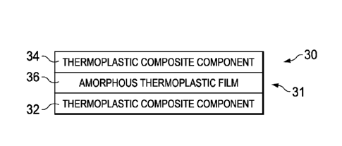
Figure 1 is an illustration of a diagrammatic view of an
integrated composite structure having thermoplastic composite
components joined together by an amorphous thermoplastic film.
Figure 2 is a drawing of a photomicrograph showing the
cross-sectional interface between one of the thermoplastic
composite components and an amorphous thermoplastic film forming
part of the integrated composite structure shown in Figure 1.
Figure 3 is a drawing of a photomicrograph showing the
fused cross-sectional interface between the thermoplastic
composite components of the integrated composite structure.
Figures 4-7 are illustrations of cross-sectional,
diagrammatic views showing the steps of a method of fabricating
the integrated composite structure shown in Figure 1.
7
CA 028974 2015-021
WO 2014/088704 PCT/US2013/065238
Figure 8 is an illustration of a flow diagram of a method
of fabricating the integrated composite structure shown in
Figure 1.
Figure 9 is an illustration of a cross-sectional view of a
pre-consolidated thermoplastic composite hat stringer being
placed on a pre-consolidated thermoplastic composite skin.
Figure 10 is an illustration similar to Figure 9 but
showing the hat stringer having been placed on the skin and
tooling installed for compressing the thermoplastic films
together.
Figure 11 is an illustration of a cross-sectional view of
pre-consolidated thermoplastic composite I-beams being assembled
with two pre-consolidated thermoplastic composite skins.
Figure 12 is an illustration similar to Figure 11, but
showing the I-beams and the skins having been assembled, and
tooling having been installed.
Figure 13 is an illustration of a diagrammatic view of a
composite structure having thermoplastic and thermoset composite
components joined together by an amorphous thermoplastic film.
Figure 14 is an illustration of a flow diagram of a method
of fabricating the composite structure shown in Figure 13.
Figure 15 is an illustration of a cross-sectional view of
an uncured thermoset composite hat stringer being placed on a
pre-consolidated thermoplastic composite skin.
8
CA 028974 2015-021
WO 2014/088704 PCT/US2013/065238
Figure 16 is an illustration similar to Figure 15 but
showing the hat Stringer having been placed on the skin and
tooling installed.
Figure 17 is an illustration of a cross-sectional view of a
thermoplastic composite hat stringer being joined to a thermoset
composite skin, also showing tooling for maintaining the shape
of the skin during curing.
Figure 18 is an illustration of a cross-sectional view of
pre-consolidated thermoplastic composite I-beams being joined to
two uncured thermoset composite skins.
Figure 19 is an illustration of a diagrammatic view of a
composite structure having a thermoplastic composite component
and a non-thermoplastic component joined together by an
amorphous thermoplastic film.
Figure 20 is an illustration of a flow diagram of a method
of fabricating the composite structure shown in Figure 19.
Figure 21 is illustration of a diagrammatic view of a
composite structure having two thermoset composite components
joined together by an amorphous thermoplastic film.
Figure 22 is an illustration of a flow diagram of a method
of fabricating the composite structure shown in Figure 21.
FIG. 23 is an illustration of a flow diagram of aircraft
production and service methodology.
FIG. 24 is illustration of a block diagram of an aircraft.
9
CA 02888974 2015-04-21
WO 2014/088704 PCT/US2013/065238
DETAILED DESCRIPTION
The disclosed embodiments provide a method of joining a
thermoplastic composite (TPC) component to another component
using a film fusion process that may be carried out at
relatively low processing temperatures with minimal surface
preparation. For example, referring to Figures 1-3, according to
one embodiment, an integrated TPC structure 30 comprises first
and second TPC components 32, 34 respectively, are joined
together by a fused thermoplastic joint 31. The thermoplastic
joint 31 is formed by an amorphous thermoplastic film 36 that
effectively fuses the first and second TPC components 32, 34
together at a processing temperature that is below the melting
point of either of the TPC components 32, 34. As best seen in
Figure 3, each of the first and second TPC components 32, 34
comprises a consolidated thermoplastic composite laminate in
which layers of fiber reinforcement 48 are held in a
thermoplastic resin matrix 39
(Figure 2). The fiber
reinforcement 48 may comprise unidirectional or bi-directional
fibers, such as without limitation, glass or carbon fibers,
arranged in desired fiber orientations according to a predefined
ply schedule (not shown). As will be discussed below in more
detail, each of the TPC components 32, 34 may be formed from a
stack of a suitable thermoplastic pre-preg which is co-
consolidated with a layer of the amorphous thermoplastic film
36.
Thermoplastic polymers may be amorphous or semi-
crystalline. Amorphous thermoplastic polymers are substantially
lacking in positional order on the molecular scale, whereas
semi-crystalline thermoplastic polymers may contain both
crystalline and amorphous regions. The degree of crystallinity
of a thermoplastic polymer is affected by structure,
temperature, molecular weight, stereochemistry and processing
conditions. Semi-crystalline thermoplastic polymers have melt
CA 02E038974 2015-04-21
WO 2014/088704 PCT/US2013/065238
temperatures Tm at which the ordered regions of molecules break-
up and become disordered. In contrast, in amorphous
thermoplastic polymers, amorphous regions of the molecules
soften over a relatively wide temperature range which is below
the melt temperature Tm, referred to as the glass transition
temperature Tg. Thermoplastic polymers that are fully amorphous
do not melt, and therefore do not have a melt temperature Tm.
However, all thermoplastic polymers exhibit a glass transition
temperature Tg. According to the disclosed embodiments, the
resin matrix .. 39 (Figure 2) may be a semi-crystalline
thermoplastic polymer, such as, without limitation, members of
the polyaryletherketone (PAEK) family including but not limited
to polyetheretherketone ("PEEK") and polyetherketoneketone
("PEKK"), and polyphenylsulfone ("PPS"), to name only a few. The
resin matrix 39, including the semi-crystalline thermoplastic
polymers mentioned immediately above, may have a melt
temperature Tm which is above approximately 500 F, typically
above 650 F.
The amorphous thermoplastic film 36 is an amorphous polymer
that may have a glass transition temperature Tg above
approximately 140 C and below approximately 500 F, and other
mechanical, thermal and physical properties that are suitable
for the application. The particular polymer selected for use as
the amorphous thermoplastic film 36 should be compatible with
the semi-crystalline thermoplastic polymer resin matrix 39, and
should be stable at temperatures that are typically used to
process thermoplastic parts, for example and without limitation
from approximately 650 F to approximately 800 F. In one
embodiment, an amorphous thermoplastic film 36 may be employed
that exhibits properties allowing it to be co-consolidated with
a joining surface of each of the TPC components 32, 34. The
amorphous thermoplastic film 36 is co-consolidated with a
joining surface of each of the TPC components 32, 34, at or
11
CA 028974 2015-021
WO 2014/088704 PCT/US2013/065238
above the temperature required for consolidation, i.e. the melt
temperature Tm of the TPC component, which typically may be in
the range of between from approximately 650 F to 800 F, in order
to prepare the TPC component 32, 34 for a secondary joining
process, discussed below. The amorphous thermoplastic film 36
exhibits properties that allow the TPC components 32, 34 to be
joined together by fusing the two amorphous thermoplastic films
36 together at temperatures below approximately 500 F, thus
avoiding the need to re-melt either of the TPC components 32, 34
during the joining process. By avoiding the need to re-melt the
TPC components 32, 34 during the joining process, the shape and
quality of the TPC components 32, 34 may be maintained.
In still another embodiment, discussed later in more
detail, an amorphous thermoplastic film 36 may be used that
exhibits properties allowing it to join a TPC substrate to a
surface of an uncured thermoset pre-preg (not shown), or to a
layer of epoxy film adhesive (not shown) on a thermoset pre-preg
of a desired shape. The thermoplastic film 36 joins the TPC
substrate to the uncured thermoset pre-preg or to the layer of
epoxy film adhesive, at the cure temperature of the thermoset
pre-preg or of the epoxy film adhesive, which may be, for
example and without limitation, approximately 350 F. The
amorphous thermoplastic film 36 may comprise a tough, rigid,
relatively high temperature engineered material, such as,
without limitation a suitable grade of PES (polyethersulfone),
having good thermal stability and creep performance. The
amorphous thermoplastic film 36 also has the ability to
withstand loads at temperatures up to 180 C for long periods of
time, and the ability to retain mechanical properties up to
210 C.
Referring now concurrently to Figures 1-3, each of the TPC
components 32, 34 comprises a consolidated stack of TPC pre-preg
12
CA 028974 2015-021
WO 2014/088704 PCT/US2013/065238
formed by reinforcement layers 48 held in a semi-crystalline
thermoplastic matrix 39. Each of the TPC components 32, 34
includes a face 33 covered by, and pre-consolidated with an
amorphous thermoplastic film 36 that forms a joining surface 37
(Figure 2). The amorphous thermoplastic film 36 may comprise one
or more layers of amorphous thermoplastic material that are
consolidated together to form a desired thickness "t" suitable
for the particular application. In one application, for example
and without limitation, the thickness "t" may be between
approximately 5 mm and 7 mm.
Each of the TPC component faces 33 is thus rich with
amorphous thermoplastic resin which may fill any cracks,
openings or voids 35 in the face 33. The amorphous thermoplastic
films 36 that are pre-consolidated with the faces 33 of the TPC
components 32, 34 may be of the type described previously. When
the joining surfaces 37 (Figure 2) of the TPC components 32, 34
are assembled and pressed together face-to-face, and the
amorphous thermoplastic films 36 are fused together as shown in
Figure 3, a fused thermoplastic joint 31 is formed which joins
the TPC components 32, 34.
As will be explained below, the amorphous thermoplastic
films 36 are respectively consolidated with the corresponding
TPC component 32, 34 at the melt temperature Tm of the semi-
crystalline resin 39 during the pre-consolidation process.
However the pre-consolidated TPC components 32, 34 are
subsequently joined together by heating the TPC structure 30 to
a temperature which is above the glass transition temperature Tg
of the amorphous thermoplastic film 36, but is substantially
below the melt temperature Tm of the semi-crystalline
thermoplastic resin39. Additional layers (not shown) of the
amorphous thermoplastic film 36 may be placed between the
joining surfaces 37 when the TPC components 32, 34 are assembled
13
CA 028974 2015-021
WO 2014/088704 PCT/US2013/065238
in order to account for manufacturing and/or assembly
tolerances. These additional layers of film 36 will fuse with
the film layers that have been pre-consolidated with the TCP
components 32, 34.
Attention is now directed to Figures 4-7 which graphically
illustrate fabrication of an integrated TPC structure 30 (Figure
1) which requires minimal surface preparation and which may be
performed using conventional ovens, vacuum bagging and/or
autoclave processing. As shown in Figure 4, a stack 32a of semi-
crystalline TPC pre-preg is assembled, following which an
amorphous thermoplastic film 36a is placed on a face 33 of the
stack 32a. The assembled stack 32a of TPC pre-preg and the film
36a are heated to at least the melt temperature of the TPC pre-
preg, while being subjected to a consolidating pressure, using
conventional techniques such as autoclave processing or vacuum
bag processing within an oven. Heating the TPC pre-preg to its
melt temperature also softens the amorphous thermoplastic film
36a, and the applied pressure results in the assembled stack 32a
of TPC pre-preg and the film 36 a being consolidated together,
as shown in Figure 5. The second TPC component 34 is assembled
and pre-consolidated in the same manner as the first TPC
component 32 described immediately above.
Each of the TPC components 32, 34 having been pre-
consolidated as described above, the TPC components 32, 34 are
assembled, as shown in Figure 6 by placing the joining surfaces
37 formed by the amorphous thermoplastic films 36a, 36b on the
components 32, 34 in face-to-face contact with each other. With
the two TPC components 32, 34 having been assembled together,
they are then heated and subjected to a consolidating pressure
as shown in Figure 7. The two TPC components 32, 34 are heated
to a temperature that is at least the glass transition
temperature Tg of the films 36a, 36h, but which is substantially
14
CA 028974 2015-021
WO 2014/088704 PCT/US2013/065238
below the melt temperature Tm of the semi-crystalline TPC. For
example, the two TPC components 32, 34 may be heated to a
temperature that is between approximately 418 F and
approximately 500 F where the glass transition temperature Tg of
the film 36a, 36b is around 418 F. The joining process described
in connection with Figures 4-7 may be carried out using only the
tooling required to apply the necessary consolidation pressure,
since the two TPC components 32, 34 are pre-consolidated and
only enough pressure is needed to compress and consolidate the
two amorphous thermoplastic films 36a, 36b.
Figure 8 illustrates the overall steps of a method of
joining first and second TPC components 32, 34 together.
Beginning at step 38, a first TPC component 32 is produced
which, as previously described, comprises co-consolidating an
amorphous thermoplastic film 36a with a first stack 32a of semi-
crystalline TPC pre-preg. At step 40, a second TPC component 34
is produced, which comprises co-consolidating a second amorphous
thermoplastic film 36b with a second stack 32b of semi-
crystalline TPC pre-preg. At step 42, the first and second TPC
components 32, 34 are assembled by placing the joining surfaces
37 of the films 36a, 36b together, in face-to-face contact.
Although not shown in Figure 8, additional layers of amorphous
thermoplastic film 36 may be co-consolidated with either or both
of the joining surfaces 37 it steps 38, 40 to account for
assembly tolerances. Then, at 44, amorphous thermoplastic films
are compressed together by applying pressure to the first and
second TPC components 32, 34. Finally, at step 46, the amorphous
thermoplastic films 36a, 36b are fused together by heating the
films 36a, 36b to a temperature above their glass transition
temperatures Tg but below a temperature of approximately 500 F.
Attention is now directed to Figures 9 and 10 which show
one typical application of the disclosed method of joining two
CA 2888974 2017-03-08
semi-crystalline TPC components using an amorphous thermoplastic
film of the type previously described. In this example, the two
semi-crystalline TPC components respectively comprise a hat shaped
TCP stringer 50, and a TCP skin 56. In the illustrated example, the
Stringer 50 and the skin 56 are substantially straight, however in
other examples the may have one or more curves or contours,
depending upon the application. The stringer 50 includes a pair of
laterally extending flanges 52 to which the amorphous thermoplastic
film 36a has been pre-consolidated in a fabrication process similar
to that previously described in connection with Figures 4-8.
Similarly, a pair of spaced apart amorphous thermoplastic films 36h
is pre-consolidated with the skin 56, in alignment with the flanges
52.
The stringer 50 and the skin 56 having each been pre-
consolidated with their respective films 36a, 36b, the stringer 50
is then placed 54 on the skin 56, such that the amorphous
thermoplastic films 36a, 36b are aligned and brought into face-to-
face contact with each other.
Referring particularly to Figure 10, simple upper and lower
tools 58, 60 are respectively placed on the flanges 52 and the
bottom of the skin 56 in preparation for carrying out a secondary
joining process in which stringer 50 is joined to the skin 56 by
fusing the films 36a, 36b together. It should be observed here that
the upper and lower tools 58, 60 need only contact the flanges 52
and the skin 56 in the areas where the amorphous thermoplastic
films 36a, 36b are located.
The films 36a, 36b are heated to a temperature below
approximately 500 F, but at least to their glass transition
temperature Tg, which is below the melt temperature Tm of the fully
consolidated, semi-crystalline TPC stringer 50 and skin
16
CA 02E038974 2015-04-21
WO 2014/088704 PCT/US2013/065238
56. This heating may be achieved by placing the assembled
stringer 50 and skin 56 in an autoclave or an oven, although it
may be possible to apply localized heat in the area of the films
36a, 36b using infrared heating, heated tooling or other
techniques. The upper and lower tools 58, 60 are forced together
by consolidation pressure 62 applied by any suitable means in
order to compress the films 36a, 36b together and thereby fusing
them as they are heated above their glass transition temperature
Tg. The necessary consolidation pressure 62 may be applied to
the tool 58, 60 using mechanical means such as a press (not
shown), or vacuum bagging and/or autoclave pressure. A
relatively low level of pressure, for example, equal to or less
than approximately 100 psi may be required to consolidate the
two films 36a, 36b together.
Figures 11 and 12 illustrate another application of the
method of joining fully consolidated semi-crystalline TPC I-
beams 64 with two semi-crystalline TPC skins 56a, 56b. Each of
the I-beams 64 includes a pair of spaced apart flanges or caps
68 connected by a central web 66. As best seen in Figure 11, the
I-beams 64 and the skins 56a, 56b are prefabricated and then
joined together in a secondary joining operation at relatively
low processing temperatures and pressure according to the
disclosed method. Each of the I-beams 64 is prefabricated by
laying up and forming TPC pre-preg, following which amorphous
thermoplastic film 36a is placed over each of the caps 68. The
films 36a are then co-consolidated with the beams 64 as
previously described in which TPC I-beam layups are heated to
their melt temperature, typically around 650' or higher, and
consolidation pressure is applied through suitable tooling (not
shown) in order to consolidate the TPC layups along with the
amorphous thermoplastic films 36a. The semi-crystalline TPC
skins 56a, 56b are fabricated in a similar manner. The skins
56a, 56b are laid up using stacks of TPC pre-preg, and amorphous
17
CA 02888974 2015-04-21
WO 2014/088704 PCT/US2013/065238
thermoplastic film 36b is applied to the skin 56a, 56b at
locations where the beams and 64 are to be joined to the skins
56a, 56b. The skins 56a, 56b and the films 36b are then co-
consolidated by heating the TPC pre-preg layups and the films
36b to the melt temperature of the TPC pre-preg being subjected
to consolidation pressure using any suitable means. It should be
noted here that while the I-beams 64 are shown as being joined
to a pair of skins 56a, 56b, in other examples, the I-beams 64
may be joined to only a single skin 56. Moreover, caps, flanges
or other surfaces of composite beams having other cross-
sectional shapes may be joined to one or more composite skins
using the disclosed method and the amorphous thermoplastic film
36.
Referring particularly to Figure 12, similar to the
application shown in Figures 9 and 10, the I-beams 64 may be
joined to the skins 56a, 56b, using relatively simple upper and
lower tools 70, 72 to apply consolidating pressure 76 to the
assembled I-beams 64 and skins 56a, 56b. The consolidation
pressure 76 may be applied to the tools 70, 72 using mechanical
means such as a press (not shown), vacuum bagging and/or
autoclave processing. The necessary heating may be achieved
using the local application of heat, or within an oven or an
autoclave. Since the I-beams 64 and the skins 56a, 56b are pre-
consolidated, only enough applied pressure is required to effect
consolidation of the semi-crystalline thermoplastic films 36a,
36b, for example equal to or less than approximately 100 psi.
Similarly, since the I-beams 64 and the skins 56a, 56b have been
pre-consolidated, is not necessary to re-heat the consolidated
semi-crystalline TPC to its melt temperature, but rather it is
only necessary to heat the films 36a, 36b to their glass
transition temperature which is below approximately 475 F.
Further, since both the I-beams 64 and the skins 56a, 56b are
pre-consolidated, costly and/or complicated tooling is not
18
CA 02888974 2015-04-21
WO 2014/088704 PCT/US2013/065238
required to form or consolidate either the I-beams 64, or the
skins 56a, 56b. Optionally, it may be desirable to provide side
tools 74 on each side of the webs 66 in order to avoid undesired
deformation of the webs 66 and/or to more effectively transfer
the applied loads through the I-beams 64 to the interface
between the films 36a, 36b.
Referring now to Figure 13, the disclosed joining method
employing an amorphous thermoplastic film 84 may be used to
fabricate a composite structure 78 by joining a semi-crystalline
TPC component 80 to a thermoset composite component 82 at the
cure temperature of the thermoset composite component 82.
Typically, the temperature at which the thermoset composite
component 82 cures is below the glass transition temperature Tg
of the semi-crystalline TPC component 80, typically less than
approximately 400 F. The amorphous thermoplastic film 84
remains glassy at the cure temperature of the semi-crystalline
TPC component 80. The resin forming the matrix of the semi-
crystalline TPC component 80 reaches a minimum viscosity during
cure, and has excellent affinity toward the amorphous
thermoplastic film 84. Due to this affinity, the thermoset resin
wets the surface of the amorphous thermoplastic film 84. Upon
cure, a strong bond is obtained between the amorphous
thermoplastic film 84 and the thermoset resin of the semi-
crystalline TPC component 80, producing a fused thermoplastic
joint 31 between the semi-crystalline TPC component 82 the
thermoset component 82. In some embodiments, some distribution
of the thermoset resin into the amorphous thermoplastic film 84
may occur, which may strengthen the bond.
Figure 14 illustrates the overall steps of a method of
joining the TPC component 80 with the thermoset component 82.
Beginning at step 86, a first composite component 80 is formed
of by co-consolidating an amorphous thermoplastic film 36 and a
19
CA 028974 2015-021
WO 2014/088704 PCT/US2013/065238
stack of TPC pre-preg. At step 88, a second composite component
82 is formed by, for example, laying up a stack of thermoset
composite pre-preg. The thermoset composite pre-preg may
comprise, for example and without limitation a thermoset resin
such as epoxy that is reinforced with unidirectional or
bidirectional fibers such as carbon fibers, however other
thermoset resins and fiber materials are possible. Typically,
the thermoset resin may have a cure temperature below
approximately 400 F, for example approximately 350 F.
At step 90, the first and second composite components 80,
82 are assembled by placing the amorphous thermoplastic film 36
of the TPC component 80 against the stack of thermoset composite
pre-preg. Although not shown in Figure 14, an additional layer
of the amorphous thermoplastic film 36 optionally may be placed
on the stack of the thermoset composite pre-preg. This
additional layer of the film 36 later fuses together with the
film 36 that has been previously co-consolidated with the stack
of TPC pre-preg. The additional layer of the film 36 may be used
to compensate for manufacturing and/or assembling tolerances
and/or mismatch of problems occurring during consolidation,
thereby assuring that the fused thermoplastic joint 31 is
continuous and has a preselected thickness throughout. At step
92 the stack of thermoset composite pre-preg is cured by heating
the thermoset pre-preg along with the TPC component 82 to the
cure temperature of the thermoset resin. At this cure
temperature, the affinity of the thermoset resin toward the
glassy amorphous thermoplastic film 36 results in forming a
fused thermoplastic joint 31 being formed between the TPC
component 80 and the cured thermoset composite component 82.
Thus, it may be appreciated that during curing of the thermoset
composite pre-preg in step 92, the pre-consolidated TPC
component 80 does not re-melt since the cure temperature of the
CA 028974 2015-021
WO 2014/088704 PCT/US2013/065238
thermoset resin is less than the melt temperature Tm of the TPC
component 80.
Figures 15 and 16 illustrate one application of the method
of joining a pre-consolidated TPC component to a thermoset
composite component using a fused thermoplastic joint 31 that is
formed during curing of the thermoset composite component as
previously described in connection with Figures 13 and 14. In
this example, a hat stringer 94 formed of a thermoset composite
such as, without limitation, carbon fiber epoxy, is joined to a
pre-consolidated TPC skin 98 comprising a pre-consolidated stack
48 of TPC pre-preg. The hat stringer 94 includes laterally
extending flanges 96. An amorphous thermoplastic film 36 is co-
consolidated on the surface of the skin 98 at locations
corresponding to the placement of the flanges 96 on the skin 98.
The amorphous thermoplastic film 36 may be of the type
previously described and is chosen to suit the cure temperature
of the thermoset composite used to fabricate the stringer 94.
The thermoset composite hat stringer 94 may comprise a multi-ply
stack of fiber reinforced thermoset resin that is laid up and
formed to the desired shape of the hat stringer 94. The uncured
hat stringer 94 is then placed 100 on the pre-consolidated TPC
skin 98, with the flanges 96 in face-to-face contact with the
film 36.
Referring now particularly to Figure 16, a tool 102 having
a cavity matched to the outer mold line of the stringer 94 is
placed over the stringer 94, and a removable mandrel 104 may be
placed within the stringer 94 in order to react consolidation
force 106 applied to the hat stringer 94 during the curing
process. The tool 102 along with the mandrel 104 assists in
maintaining the shape of the hat stringer 94 during curing. The
assembly of the hat stringer 94 and the skin 98 are subjected to
a combination of heat and pressure using conventional autoclave
21
CA 028974 2015-021
WO 2014/088704 PCT/US2013/065238
or out-of-autoclave processing techniques. During curing,
thermoset stringer 94 is heated to which cure temperature of the
thermoset resin, which may be approximately 350 F. During
curing, the cure temperature is sufficient to cause the
amorphous thermoplastic film 36 to become glassy and fuse with
the viscous thermoset resin, thereby forming a fused
thermoplastic joint 31 between the stringer 94 and the skin 98.
During the cure process, the TPC skin 98 maintains its shape and
does not de-laminate or loose desirable qualities as it is not
re-melt at the relatively low temperatures required for curing
of the thermoset stringer 94.
Figure 17 illustrates still another application of the
disclosed joining method using an amorphous thermoplastic film
36 to form a fused thermoplastic joint 31 between two composite
components. In this example, a pre-consolidated TPC laminate hat
stringer 108 is joined by the film 36 to a thermoset composite
laminate skin 112. Simple upper tools 114 are used to apply
pressure 118 to flanges 110 of the stringer 108 in order to
force film 36 pre-consolidated on the flanges 110 against the
thermoset composite skin 112 during curing. A lower tool 116 may
be employed to maintain the shape of the thermoset composite
skin 112 during the cure process. Also, an internal, mandrel-
like tool 104 may be placed inside of the stringer 108, bearing
on the thermoset composite skin 112, in order to transmit
consolidation pressure to the skin 112 beneath the hat portion
108a of the stringer 108 during consolidation and curing. During
curing, the thermoset composite skin 112 is heated to its cure
temperature, typically approximately 350 F, which is sufficient
to cause the film 36 to become glassy and fuse with the viscous
thermoset resin of the skin 112, thereby forming a strong,
robust fused thermoplastic joint 31.
22
CA 028974 2015-021
WO 2014/088704 PCT/US2013/065238
Figure 18 illustrates another application of the disclosed
method in which the TCP I-beams 120 are joined to thermoset
composite skins 112a, 112b using the previously described
amorphous thermoplastic film 36. This application is similar to
that previously described in connection with Figures 11 and 12.
However in this example, additional tools may be used to
maintain the shape of the skins 112a, 112b the during the cure
process in which the thermoset resin of the skins 112a, 112b
becomes viscous and fuses with the glassy amorphous
thermoplastic film 36. The additional tooling comprises upper
and lower tools 126, 128, a center tool 130 and outer tools 132
which collectively engage and contain the surfaces of the skins
112a, 112b. Side tools 134 may also be positioned on opposite
sides of the webs 122 in order to avoid undesired deformation of
the webs 122, and to assist in distributing consolidation force
applied to the amorphous thermoplastic film 36 during curing.
While the applications previously described involved
joining a TCP component to a thermoset composite component, it
may be possible to employ the disclosed method to join a TPC
component to a component formed of other materials such as,
without limitation, metals and ceramics. Thus, referring to
Figure 19, the previously described amorphous thermoplastic film
36 may be employed to fabricate a composite structure 136 that
includes forming a fused thermoplastic joint 31 between a TCP
component 138 and a component 140 formed of a non-thermoplastic
material such as, without limitation, a metal or a ceramic.
Beginning at step 142, amorphous thermoplastic film 36 is
co-consolidated with a stack of semi-crystalline TPC pre-preg.
At 144, the co-consolidated TPC pre-preg and film 36 are
assembled with a non-thermoplastic component 140, by placing the
co-consolidated amorphous thermoplastic film 36 against the non-
thermoplastic component 140. At step 146, pressure is applied to
23
CA 2888974 2017-03-08
the assembly of the co-consolidated TPC stack/film and the non-
thermoplastic component 140 in order to press the film 36 against
the non-thermoplastic component 140. At step 148, the amorphous a
plastic film 36 is heated to a temperature below approximately
500 F but at least to its glass transition temperature, causing it
to flow. The flowing film 36 forms a fused thermoplastic joint 31
between the pre-consolidated TOP component 138 and the non-
thermoplastic component 140.
Figure 21 illustrates still another application of the
disclosed method, in which an amorphous thermoplastic film 36 is
employed to fabricate a thermoset composite structure 150 which may
have improved bondline thickness consistency and/or toughness. The
amorphous thermoplastic film 36 is used to produce a fused
thermoplastic joint 31 between two thermoset composite components
152. The thermoset composite structure 150 may be produced by the
method shown in Figure 22. At steps 156 and 158, first and second
stacks of thermoset pre-preg are respectively formed. At step 160,
the amorphous thermoplastic film 36 is placed between joining
surfaces of the first and second stacks of uncured thermoset pre-
preg. At step 162 the first and second stacks of thermoset pre-preg
are consolidated and thermally co-cured, along with the amorphous
thermoplastic film. During the cure process, the pre-preg and the
film are heated to the cure temperature of the thermoset resin,
typically approximately 350 F at which point the amorphous
thermoplastic film 36 becomes glassy and fuses with the viscous
thermoset resin. Consolidating pressure applied by the vacuum
bagging or autoclave processing forces the two stacks of thermoset
pre-preg against the film 36 to assist in the thermoset resin to-
thermoplastic film fusion. Because the amorphous thermoplastic film
36 can be pre-manufactured with a controlled thickness, the fused
thermoplastic joint 31 may have a bondline thickness that is both
consistent and which may be controlled. The
24
CA 028974 2015-021
WO 2014/088704 PCT/US2013/065238
thermoplastic joint 31 may also exhibit improved toughness
compared to joints relying on bonding adhesives. Further, the
amorphous thermoplastic film 36 may be selected to have a
desired hardness which may be less than that of the thermoset
composite components 152, 154, allowing the fused thermoplastic
joint 31 to better absorb energy due to shock, vibration or
impacts experienced by the composite structure. Thus, the
thermoset composite structure 150 may exhibit improve impact
resistance.
Embodiments of the disclosure may find use in a variety of
potential applications, particularly in the transportation
industry, including for example, aerospace, marine, automotive
applications and other application where composite components
are joined together. In
the aircraft industry, the disclosed
joining method may be used to produce low-cost, high-performance
integrated structures such as stiffeners of various cross-
sectional shapes, torque boxes used for doors, flight control
structures, wing, and fuselage structures. Thus, referring now
to Figures 23 and 24, embodiments of the disclosure may be used
in the context of an aircraft manufacturing and service method
164 as shown in Figure 23 and an aircraft 166 as shown in Figure
24.
During pre-production, exemplary method 164 may include
specification and design 168 of the aircraft 166 and material
procurement 170.
During production, component and subassembly
manufacturing 172 and system integration 174 of the aircraft 166
takes place.
Thereafter, the aircraft 166 may go through
certification and delivery 176 in order to be placed in service
178. While
in service by a customer, the aircraft 166 is
scheduled for routine maintenance and service 180, which may
also include modification, reconfiguration, refurbishment, and
so on.
CA 028974 2015-021
WO 2014/088704 PCT/US2013/065238
Each of the processes of method 164 may be performed or
carried out by a system integrator, a third party, and/or an
operator (e.g., a customer). For
the purposes of this
description, a system integrator may include without limitation
any number of aircraft manufacturers and major-system
subcontractors; a third party may include without limitation any
number of vendors, subcontractors, and suppliers; and an
operator may be an airline, leasing company, military entity,
service organization, and so on.
As shown in Figure 24, the aircraft 166 produced by
exemplary method 164 may include an airframe 182 with a
plurality of systems 184 and an interior 186. Examples of high-
level systems 184 include one or more of a propulsion system
188, an electrical system 190, a hydraulic system 192, and an
environmental system 194. Any
number of other systems may be
included.
Although an aerospace example is shown, the
principles of the disclosure may be applied to other industries,
such as the marine and automotive industries.
Systems and methods embodied herein may be employed during
any one or more of the stages of the production and service
method 164. For
example, components Or subassemblies
corresponding to production process 172 may be fabricated or
manufactured in a manner similar to components or subassemblies
produced while the aircraft 166 is in service. Also,
one or
more apparatus embodiments, method embodiments, or a combination
thereof may be utilized during the production stages 172 and
174, for example, by substantially expediting assembly of or
reducing the cost of an aircraft 166. Similarly, one or more of
apparatus embodiments, method embodiments, or a combination
thereof may be utilized while the aircraft 166 is in service,
for example and without limitation, to maintenance and service
180.
26
CA 02888974 2015-04-21
WO 2014/088704 PCT/US2013/065238
The description of the different illustrative embodiments
has been presented for purposes of illustration and description,
and is not intended to be exhaustive or limited to the
embodiments in the form disclosed. Many
modifications and
variations will be apparent to those of ordinary skill in the
art.
Further, different illustrative embodiments may provide
different advantages as compared to other illustrative
embodiments. The embodiment or embodiments selected are chosen
and described in order to best explain the principles of the
embodiments, the practical application, and to enable others of
ordinary skill in the art to understand the disclosure for
various embodiments with various modifications as are suited to
the particular use contemplated.
27