Note: Descriptions are shown in the official language in which they were submitted.
ELECTRONIC LOCK HAVING HARDWARE BASED MULTI-WIRELESS
PROFILE DETECTION AND SETTING
TECHNICAL FIELD
The present invention relates to electronic locks, and, more particularly, to
an
electronic lock having hardware based multi-wireless profile detection and
setting.
BACKGROUND AND SUMMARY
Electronic locks are commercially available having a capability of
communicating via using a standardized short range wireless radio frequency
(r.f.)
communication protocol, such as for example, the Zigbee and Z-Wave wireless
communications protocols. Lock and systems developers often customize their
respective commercial offerings to include customer specific communication
hardware
and methods that utilize variations of standard protocols. As such, each
electronic lock
hardware unit has to be customized to support a particular customer's system
communications configuration of a plurality of potential customer
configurations.
Thus, a manufacturer of electronic locks must have on-hand separate electronic
lock
hardware units, i.e., stock keeping units (SKUs), which satisfy the
communications
-1-
CA 2888999 2020-01-13
CA 02888999 2015-04-21
WO 2014/066391
PCT/US2013/066185
requirements of each of its customers, thus adding cost and complexity in the
entire
supply chain in addition to potentially adding confusion in the distribution
channel for
the distributors and dealers who deal with these variations.
What is needed in the art is an electronic lock having hardware based multi-
wireless profile detection and setting, wherein a single electronic lock is
configurable to
enable an installer or user to set a desired wireless communication protocol
profile, or
configuration, to allow the electronic lock to communicatively join the system
in which
the electronic lock is to be incorporated.
According to one aspect, the present invention provides an electronic lock.
The
lock may include a latch assembly including a bolt movable between an extended
position and a retracted position and a circuit configured to control movement
of the
bolt. The circuit includes a processing unit, a memory unit, a wireless module
and a
hardware profile selector. A plurality of wireless profiles are stored in the
memory
which correspond to wireless communications protocols. The wireless module is
configured to communicate wirelessly using a selected wireless communication
protocol, which is set by the hardware profile selector. In some embodiments,
at least a
portion of the wireless profiles stored in the memory unit correspond with
multiple
profiles of the Zigbee wireless protocol and/or multiple profiles of the Z-
wave wireless
protocol. In some cases, the plurality of wireless profiles include profiles
codes
corresponding to respective wireless protocols.
Depending on the circumstances, the processing unit could be a microprocessor
with a plurality of input pins electronically connected with the hardware
profile
selector. For example, the hardware profile selector could include a plurality
of
switches configurable to set the selected wireless protocol. In some cases,
the plurality
CA 02888999 2015-04-21
WO 2014/066391
PCT/US2013/066185
of switches may be user-actuatable switches, such as dip switches, momentary
switches
and/or
slide switches.
According to another aspect, the invention provides a method of selecting a
wireless protocol for an electronic lock. For example, an electronic lock
could be
provided with a wireless module that facilitates wireless communications. The
electronic lock may include a hardware profile selector configured to set a
selected
wireless protocol used by the wireless module between a first wireless
protocol and a
second wireless protocol. The hardware profile selector is adjusted to change
the
selected wireless protocol used by the wireless module between the first
wireless
protocol and the second wireless protocol. In some cases, the adjusting step
changes
the wireless protocol between the Zigbee wireless protocol and Z-wave wireless
protocol. Embodiments are contemplated in which the hardware profile selector
includes a plurality of switches configurable to set the selected wireless
protocol. For
example, the adjusting step includes changing a position of one or more of the
plurality
of switches.
According to a further aspect, the invention provides an electronic lock with
a
wireless module configured to communicate wirelessly using a selected wireless
communication protocol. The electronic lock includes a non-transitory computer-
readable medium having wireless profile data including a plurality of wireless
profile
codes and a computer program code stored thereon. A hardware profile selector
is
provided that is configured to set the selected wireless communication
protocol. The
lock includes a processor in communication with the computer-readable memory
configured to carry out instructions in accordance with the computer program
code.
When the computer program code is executed by the processor, the processor
detects
-3-
CA 02888999 2015-04-21
WO 2014/066391
PCT/US2013/066185
the switch conditions of the hardware profile selector. This allows the
processor to
identify a selected wireless profile code stored in the computer-readable
medium
corresponding to the switch conditions of the hardware profile selector. Upon
identification of the selected protocol, the wireless module is configured to
communicate using a wireless protocol corresponding to the selected wireless
profile
code.
Additional features and advantages of the invention will become apparent to
those skilled in the art upon consideration of the following detailed
description of the
illustrated embodiment exemplifying the best mode of carrying out the
invention as
presently perceived.
BRIEF DESCRIPTION OF THE DRAWINGS
Fig. IA is a side view of an electronic lock in accordance with an embodiment
of the present invention, installed on a door and with the door show in
phantom lines.
Fig. 1B is a perspective view of the electronic lock of Fig. 1A, as viewed
from
the exterior of the door.
Fig. IC is a perspective view of the electronic lock of Fig. lA as viewed from
the interior of the door.
Fig. 2 is an exploded view of the electronic lock of Figs. 1A-1C.
Fig. 3 is a perspective view of the interior chassis of the electronic lock of
Fig.
2. with the upper cover and daughter card removed.
Fig. 4 is a block diagram of a portion of the control electronics of the
interior
chassis of Fig. 3, according to an embodiment of the invention.
-4-
CA 02888999 2015-04-21
WO 2014/066391
PCT/US2013/066185
Corresponding reference characters indicate corresponding parts throughout the
several views. The exemplifications set out herein illustrate an embodiment of
the
invention, and such exemplifications are not to be construed as limiting the
scope of the
invention in any manner.
DETAILED DESCRIPTION OF THE DRAWINGS
Referring now to the drawings and particularly to Figs. 1A-1C and 2, there is
shown an electronic lock (EL) in accordance with an embodiment of the present
invention for mounting on a door D, and which includes an interior chassis 1,
an
exterior chassis 2, a mounting plate 3, an adapter 4, a latch assembly 5, and
a strike 6.
As shown in Fig. 2, latch assembly 5 is of a configuration well known in the
art,
and includes a bolt actuator mechanism 7, and a bolt 8. Mounting plate 3 is
used to
mount the electronic lock to the door D. Adapter 4 is used to adapt the
electronic lock
to a particular hole opening in the door D.
Referring also to Fig. 3, interior chassis 1 includes the electronics
circuitry 9 for
the electronic lock, and further includes a manual turnpiece 10. Manual
turnpiece 10 is
used on the interior side of door D to operate the bolt actuator mechanism 7
of latch
assembly 5, and in turn to extend and retract bolt 8 (see also Fig. 1C). The
electronics
circuitry 9 includes a base board 11 and a removable daughter card 12. In Fig.
3, a
removable cover 13 is provided to cover over the base board 11 and daughter
card 12,
when cover 13 is in the installed position. Daughter card 12 is a wireless
communications module that facilitates wireless communications with an
external
device though a desired wireless communications protocol, e.g., Zigbee, Z-
wave, etc.
-5-
CA 02888999 2015-04-21
WO 2014/066391
PCT/US2013/066185
Referring again to Fig 2, exterior chassis 2 includes a keypad 14 for
receiving a
user input. Keypad 14 is electrically connected to the base board 11 of
electronics
circuitry 9, such as for example by an electrical cable 15. When the user
inputs a valid
code via keypad 14 that is recognized by the electronics circuitry 9, an
electrical motor
(not show) is energized to retract the bolt 8 of latch assembly 5, thus pei
miffing door D
(see Fig. 1B) to be opened from a closed position. Alternatively, a key
actuator 16,
having a removable key K, is provided for manually operating latch assembly 5
from
the exterior of the door D.
Referring particularly to Figs. 3 and Fig. 4, daughter card 12 is a wireless
communications module that facilitates wireless communications with an
external
device through a desired wireless communications protocol, e.g., Zigbee, Z-
wave, etc.
In accordance with an embodiment of the present invention, base board 11
and/or
daughter card 12 of electronics circuitry 9 is configurable to enable an
installer or user
to set a desired wireless protocol Profile, i.e., configuration, corresponding
to a
standard wireless protocol or a desired variation of the standard wireless
protocol, so as
to allow the electronic lock to communicatively join a system into which the
electronic
lock is being inserted. For example, multiple profiles could be provided for
the Zigbee
protocol based on different manufacturer implementations. Likewise, as an
example,
multiple profiles could be provided for the Z-wave protocol based on different
manufacturer implementations.
Electronics circuitry 9 may include, for example, an EMBER Corporation
EM357 chip along with associated devices to handle all IEEE 802.15.4
operations. The
chip and associated devices is driven by a 24.00 MHz crystal which is used to
produce
-6-
CA 02888999 2015-04-21
WO 2014/066391
PCT/US2013/066185
other internal clocks. Additional devices, such as LED's, switches, other
integrated
circuits, antenna and others are designed into electronics circuitry 9.
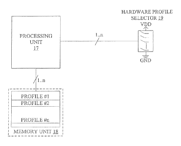
Referring to Fig. 4, electronics circuitry 9 includes a processing unit 17, a
memory unit 18, and a hardware profile selector 19. Processing unit 17
includes a
commercially available microprocessor or a custom built processing unit (ASIC
=
Application Specific Integrated Circuit) and associated input/output (I/0)
circuitry, and
is configured for electronic communication with memory unit 18 and hardware
profile
selector 19. A number of GPIO (General Input-Output) pins are connected to the
microprocessor. The state of these CiPIO pins can be set by the user (digital
High "1" or
Low "0") via a set of switches of the hardware profile selector 19. Processing
unit 17 is
configured such that during a system boot-up process (e.g., at power up) or a
designated profile selection event, processing unit 17 reads the configuration
of these
GPIO pins.
Memory unit 18 is an electronic semiconductor memory device, such as for
example, a read only memory (ROM), erasable programmable read only memory
(EPROM), electrically erasable programmable read only memory (EEPROM),
embedded memory in the processing unit 17 etc. As shown in Fig. 4, memory unit
18
is configured to store a plurality of wireless protocol Profiles #1-#n
associated with the
desired wireless communication protocol. Each wireless protocol Profile stored
in
memory unit 18 corresponds to a standard wireless protocol and/or a specific
variation
of the standard wireless protocol as dictated by the wireless communications
system
requirements of a respective customer. Alternatively, or in addition, it is
contemplated
that memory unit 18 may store a plurality of sets of wireless protocol
Profiles, with
-7-
CA 02888999 2015-04-21
WO 2014/066391
PCT/US2013/066185
each set of wireless protocol Profiles being associated with a respective
wireless
communication protocol.
Hardware profile selector 19 is a set of switches that is used to generate a
multi-
digit binary number, wherein for example, a switch open condition represents a
binary
"0" Low and a switch closed condition represents a binary "1" High. The number
of
switches used and/or physically present in hardware profile selector 19 will
determine
the number of wireless protocol Profiles that are selectable in memory unit
18. For
example, three switches may be used for the binary range of 000 through 111,
thus
providing eight possible combinations that may be used to access eight
different
wireless protocol Profiles. In some embodiments, other computer number systems
could be used to encode the profile location or position while the current
invention
shows a binary coded profile position. In some cases, the hardware profile
selector 19
could be configured for negative logic so a "0" corresponds with an "on" or
"high"
condition.
Hardware profile selector 19 may be a set of DIP switches, or alternatively a
combination of DIP switches and one or more momentary switches. Such momentary
switches may be a designated dual purpose switch, such as one or more of the
buttons
of the keypad 14, or other momentary switch(es) on base board 11. The one or
more
momentary switches, for example, would be used in wireless protocol profile
selection
at power up only or at a designated profile selection event, such as at an
installer's
specific request for profile selection, when a physical interaction with the
user/installer
is required for switch condition setting selection in hardware profile
selector 19.
However, non-momentary switches, such as DIP switches, once set do not require
physical interaction with the user/installer during wireless protocol profile
selection. In
-8-
CA 02888999 2015-04-21
WO 2014/066391
PCT/US2013/066185
some embodiments, for example, a slide switch sold under model number CUS-12TB
by Copal Electronics could be used in combination with one or more momentary
switches and/or DIP switches of hardware profile selector 19.
In accordance with an embodiment, on boot-up or a designated profile selection
event, processing unit 17 executes program instructions to run a profile
selection
scheme in which processing unit 17 of electronics circuitry 9 reads the switch
positions
of hardware profile selector 19, and automatically retrieves from memory unit
18 a
desired wireless communication protocol Profile from the plurality of wireless
protocol
Profiles stored in memory unit 18. For example, a Profile code 101 of hardware
profile
selector 19 may be correlated to wireless protocol Profile #1 in memory unit
18, a
Profile code 110 of hardware profile selector 19 may be correlated to wireless
protocol
Profile #2 in memory unit 18, etc. Processing unit 17 then executes the
selected
wireless protocol Profile in configuring electronics circuitry 9 for the
communication
system in which the electronic lock is being installed.
If no change is detected (e.g., since last boot-up), processing unit 17 will
execute a Default or Loaded Profile.
If a change is detected (since last boot-up), then the wireless protocol
Profile
corresponding to the configuration defined by the switch settings will be
loaded in the
program execution memory of processing unit 17. Program execution memory may
be
processor memory on the microprocessor module, or alternatively may be a
portion of
memory unit 18.
From this time on, the electronics circuitry 9 will execute the same profile.
-9-
CA 02888999 2015-04-21
WO 2014/066391 PCT/US2013/066185
To switch to a different Profile of the wireless protocol Profiles stored in
memory unit 18, the following sequence is executed:
a. power down electronics circuitry 9 (or use of digital switch to perform
soft reset);
b. reconfigure state of GPIO pins through a selection of the switch
conditions in the hardware profile selector 19;
c. power electronics circuitry 9 back up;
d. processing unit 17 loads the new wireless protocol Profile into
processor
memory from memory unit 18 based on the switch conditions set in the hardware
profile selector 19 and the new wireless protocol Profile is executed from
that time on.
While the GPIOs are typically used or read by the microprocessor of processing
unit 17, it is contemplated that any pins or input could be used that can be
read at
power-up or before the Profile code is required to load.
Advantageously, the present invention allows the flexibility to add new
profiles
on the same electronic lock (EL) unit, i.e., stock keeping unit (SKU), to
accommodate
the various wireless protocol Profile configuration requirements of multiple
customers,
without having to create new hardware specific to a particular customer, e.g.,
system
provider. Also, the present invention provides flexibility during
manufacturing of the
electronic lock (EL) SKU if and when a new custom wireless protocol Profile is
required by a customer.
While this invention has been described with respect to an embodiment of the
invention, the present invention may be further modified within the spirit and
scope of
-10-
CA 02888999 2015-04-21
WO 2014/066391
PCT/US2013/066185
this disclosure. "[his application is therefore intended to cover any
variations, uses, or
adaptations of the invention using its general principles. Further, this
application is
intended to cover such departures from the present disclosure as come within
known or
customary practice in the art to which this invention pertains.
Although the present disclosure has been described with reference to
particular
means, materials and embodiments, from the foregoing description, one skilled
in the
art can easily ascertain the essential characteristics of the present
disclosure and various
changes and modifications may be made to adapt the various uses and
characteristics
without departing from the spirit and scope of the present invention as set
forth in the
following claims.
-11-