Note: Descriptions are shown in the official language in which they were submitted.
CA 02889040 2016-07-13
BUCKET FOR A MOP
BACKGROUND OF THE INVENTION
1. Field of the invention
The present invention is related to a bucket, and more particularly to a
bucket for a mop.
2. Description of Related Art
Mopping the floor is extremely tiresome and time-consuming, let alone
intermittently cleaning the mop after the floor is completely mopped. To solve
this
problem, there is a kind of mop assembly very handy for housewives for mopping
the floor is necessary. This mop assembly has a nickname "Spin Mop" bearing a
trademark "SupaMop Hao Shen Tuo" TM. When intermittently cleaning the mop
while using this kind of mop to clean the floor, the user never has to touch
any part
of the mop, the mop is immersed in water contained in a bucket for cleaning
and
then dried due to the centrifugal force so generated by spinning the mop
inside the
bucket.
It is seen that when cleaning the mop inside the bucket, the mop is raised
and then lowered as the mop is spinning. The spinning force comes from the
interior
structure of the mop, which is not the focus of this disclosure so that the
theory and
detailed structure of the mop is omitted for clarity. However, it is also
observed that
to allow the mop to be cleaned and dried, there are two separate spaces
defined to
receive the mop, which makes the bucket bulky and redundant. With this mop
assembly, especially the bulky bucket, the user will have to face difficulty
finding
an appropriate place for storage. Besides, the two separate spaces for
cleaning and
drying the mop are the primary reason that the bucket is bulky.
In view of the foregoing, a need exists in the art for an innovative bucket to
allow the mop to be cleaned and dried in the same space. In order to meet that
-1-
CA 02889040 2016-07-13
requirement, the bucket has to be compact and still work well.
SUMMARY OF THE INVENTION
Generally, a bucket made in accordance with a preferred embodiment of the
present invention is provided with an elevating assembly to enable a screen to
selectively move upward and downward as required.
In order to accomplish the objective, the bucket is preferably composed of
a casing, an elevating assembly movably received in the casing, a screen
detachably
connected to the elevating assembly and a cover enclosing a peripheral edge of
the
casing.
Another objective of the preferred embodiment of the present invention is
that the elevating assembly includes sliding tracks defined inside the casing
and a
supporting seat movably received inside the casing and having positioning
bosses
formed on peripheral edges of the supporting seat to correspond to the sliding
tracks.
Another objective of the preferred embodiment of the present invention is
that the bucket has a cover detachably connected to a peripheral edge of the
casing
to prevent any spill of the water originally contained in the casing.
Still another objective of the present invention is that the sliding tracks
are
defined in each of plates installed inside the casing.
Therefore, the design of the bucket is novel and non-obvious and meets the
patentability requirements. It is noted that the present invention has the
advantages
that the invention provides a clear and ergonomic instrument for a mop.
BRIEF DESCRIPTION OF THE DRAWINGS
An embodiment of the invention will now be described, by way of example
only, with reference to the accompanying drawings in which:
-2-
CA 02889040 2016-07-13
Fig. 1 is an exploded perspective view of the bucket constructed in
accordance with the preferred embodiment of the present invention;
Fig. 2 is an exploded perspective view of the elevating assembly in
accordance with the preferred embodiment of the present invention;
Fig. 3 is a plan view showing detailed structure of the sliding track defined
in plates to be installed in the casing of the preferred embodiment of the
present
invention;
Fig. 4 isometric view of the automatic handle assembly of the preferred
embodiment in accordance with the present invention;
Fig. 2 is another isometric view of the automatic handle assembly of the
preferred embodiment in accordance with the present invention;
Fig. 3 is an assembled view of the automatic handle assembly of the
preferred embodiment in accordance with the present invention;
Fig. 4 is a cross sectional view showing the supporting seat of the preferred
embodiment of the present invention;
Fig. 5 is a partially cross-sectional view showing the bucket of the preferred
embodiment of the present invention after assembly;
Fig. 6 is a schematic plan view showing movement of one of the positioning
bosses inside a corresponding one of the sliding tracks;
Fig. 7 is still a schematic plan view showing movement of one positioning
boss inside the corresponding sliding track in a different state, which
elevates height
of the screen relative to the casing;
Fig. 8 is a top plan view showing the cover;
Fig. 8A is a side plan view showing the cover; and
Fig. 8B is still a slide plan view showing the cover.
-3-
CA 02889040 2016-07-13
DETAILED DESCRIPTION OF THE INVENTION
The following description is merely exemplary in nature and is in no way
intended to limit the present teachings, applications, or uses. Those of skill
in the art
will recognize that the following description is merely illustrative of the
principles
of the invention, which may be applied in various ways to provide many
different
alternative embodiments.
The invention relates to a bucket for a mop which is able to extend into the
bucket for cleaning and drying afterwards. As the focus is to describe the
substantial
structure of the bucket, the internal structure of the mop is omitted for
clarity but
only the necessary element of the mop will be mentioned when necessary.
With reference to Fig. 1, it is noted that the bucket constructed in
accordance
with the preferred embodiment of the present invention has a casing 10, an
elevating
assembly composed of plates 11 and a supporting seat 20, a screen 30 and a
cover,
preferably annular in shape. The casing 10 is an annular casing with one
closed end,
an open end opposite to the closed end and a wall firmly connected to a
peripheral
edge of the closed end and a peripheral edge of the open end. It will be
appreciated
that an opening (not numbered) is provided in the wall in the bottom part of
the
casing 10 to drain the bucket, when necessary. A removable plug 12 fits in
said
opening. The plates 11 of the elevating assembly are rigidly installed inside
the
casing 10. Each of the plates 11 is provided with a sliding track W. In this
embodiment, the sliding track is defined in each of the plates 11, however,
the
sliding track W may also be defined in an inner periphery of the wall of the
casing
10.
With reference to Figs. 2 and 3, when the sliding track W is either defined
in a side face of the plate 11 or the inner periphery of the wall of the
casing 10, the
sliding track W is composed of an inlet Q, a lower stop 112, preferably a
recess
defined in a periphery defining the inlet Q, communicating with the inlet Q, a
first
guiding track 113 communicating with the lower stop 112, a first arcuate stop
B
-4-
CA 02889040 2016-07-13
formed on a periphery defining the sliding track W, a second arcuate stop D
also
formed on the periphery defining the sliding track W and substantially
continuously
formed in conjunction with the first arcuate stop B, an upper stop 111,
preferably an
indent, defined in the periphery defining the sliding track W and a second
guiding
track 114 in communication with both the inlet Q and the lower stop 112.
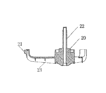
With reference to Fig. 4 and still using Figs. 1 and 2 as reference, it is
seen
that the supporting seat 20 is an integral device and has supporting legs 23
radially
extending out from a center thereof and respectively having a positioning boss
21
formed on an outer periphery of a corresponding one of the supporting legs 13
to
correspond to the sliding track W and a fixing shaft 22 formed on the center
thereof
to correspond to the screen 30.
With reference to Figs. 1-5, when the bucket of the preferred embodiment
of the present invention is assembled, the plates 11 are installed inside the
casing 10
securely against the inner periphery of the casing 10. Then, the supporting
seat 20
is received inside the casing 10 to allow the positioning bosses 21 to extend
into the
inlet Q. After the positioning bosses 21 of the supporting seat 20 are
respectively
received in the corresponding inlets Q, the positioning bosses 21 are then
securely
received inside the lower stops 112 after going through the second guiding
tracks
114.
After the supporting seat 20 is securely received in the casing 10 with the
positioning bosses 21 received in the sliding tracks W of the plates 11, the
screen 30
is then placed on top of the supporting seat 20. The screen 30 has a centrally
defined
hole (not numbered) defined to receive therein the fixing shaft 22 of the
supporting
seat 20, a sleeve 31 provided to allow the fixing shaft 22 to extend
therethrough and
a cap 32 threadingly connected to the free end of the fixing shaft 22 after
the fixing
shaft 22 extends through the hole and the sleeve 31. The cap 32 further has a
collar
321 formed to extend out of the cap 32. Furthermore, in order to allow the
screen
30 to rotate relative to the supporting seat 20, there is provided with a
bearing 40
-5-
CA 02889040 2016-07-13
which is provided around the fixing shaft 22 to support the screen 30.
Preferably,
the supporting seat 20 has a positioning recesses (shown but not numbered) to
receive therein the bearing 40 such that when the screen 30 is rotated due to
the
operation of the mop, the screen 30 is able to rotate smoothly relative to the
supporting seat 20.
Additionally, a cover a is provided to cover the peripheral edge of the casing
to prevent any accidental spill of the water inside the casing 10.
With reference to Fig. 6, before the bucket of the preferred embodiment of
the present invention is in use, the positioning bosses 21 are securely
received in the
lower stop 112 of the sliding track W, which means the screen 30 is in its
first
position. After the mop is extended into the screen, a claw (not shown) on the
mop
securely clings to the collar 321 of the cap 32 so that movement of the mop
drives
the screen 30 to move accordingly. Again, because the screen 30 is supported
by the
supporting seat 20, when positioning bosses 21 of the supporting seat 20 are
at the
lower stop 112, the first position of the screen 30 indicates that the screen
30 is also
at the lower position. Thereafter, when the mop moves upward, due to the
secure
engagement of the mop with the collar 321 of the screen 30 which is connected
to
the supporting seat 20, the upward movement of the mop drives the screen 30
along
with the supporting seat 20 upward as well As shown by the arrow in the
accompany
drawing, when the supporting seat 20 is driven to move upward, the positioning
bosses 21 move along the sliding track W. After the positioning bosses 21
reach the
top of the sliding track W, the first arcuate stop B forces the positioning
bosses 21
to fall to the upper stop 111. It is to be noted that when the positioning
bosses 21 are
located at the upper stop 111, the screen 30 is also at its second position,
which
means the screen 30 is elevated and is above the water level. Therefore, the
rotation
mechanism of the mop will drive the screen 30 to rotate as well, which will
dry the
mop accordingly.
With reference to Fig. 7, after the mop is dried, the user only needs to tilt
-6-
CA 02889040 2016-07-13
the mop a little relative to the cap 32, the mop is able to escape from
engagement
with the collar 321. However, if the mop still needs to be cleaned again, the
mop is
first lifted upward to allow the positioning bosses 21 to first leave the
restraint from
the upper stop 111 and be guided by the second arcuate stop D. Then, the
downward
movement of the mop forces the positioning bosses 21, the supporting seat 20
along
with the screen 30 to move downward and eventually the positioning bosses 21
are
again located at the lower stop 112 to allow the mop head to be immersed in
the
water for cleaning purpose.
From the above explanation, it is understood that the reciprocal movement
of the positioning bosses 21 between the lower stop 112 and the upper stop 111
allows the mop head to be dried and cleaned as required. This design is
compact and
does not require extra space as do those of the prior art.
With reference to Figs. 5, 8, 8A and 8B, it is noted that the cover a is
composed of a rim 1 and a lid 2. The rim 1 is provided with an outlet 3 for
draining
the water contained inside the casing 10, two assembly holes 4 respectively
defined
at two opposite positions relative to the outlet 3 and a hook 5 formed on an
outer
periphery of the rim 1. The lid 2 has two cylinders 6 formed on an underside
of the
lid 2 to correspond to the two assembly holes 4 of the rim 1. In addition, the
casing
has locking holes 7 defined in an upper periphery defining the open end
thereof
to correspond to the hook 5 of the rim 1 such that the rim 1 is able to be
detachably
connected to the casing 10 and the lid 2 is able to be detachably connected to
the
rim 1.
While the invention has been described in connection with what is
considered the most practical and preferred embodiment, it is understood that
various modifications will occur to those skilled in the art. This invention
is not
limited to the disclosed embodiment but is intended to cover all such
modifications
and equivalent arrangements. The scope of the claims should not be limited by
the
preferred embodiments or the examples but should be given the broadest
-7-
CA 02889040 2016-07-13
interpretation consistent with the description as a whole.
-8-