Note: Descriptions are shown in the official language in which they were submitted.
CA 02889096 2015-04-21
- 1 -
Clamping Device Having Hub Centring
The invention relates to a clamping device with hub centering for attachment
of an
automobile wheel to the shaft of a balancing machine, with a contact flange
for con-
tacting a rim of an automobile wheel, with several centering elements guided
on the
contact flange in a radially moveable, preferably slidable manner for a
centering en-
gagement in a hub centering hole of the rim and with a guided clamping sleeve
that
can be moved, preferably slid, axially to the contact flange, with the
clamping sleeve
and the centering elements being kinematically coupled or operatively
connected
such that an axial movement, particularly displacement, of the clamping sleeve
leads
to a coupled radial movement, particularly displacement, of all centering
elements.
A quick-action clamping device with hub centering for attachment of an
automobile
wheel to the shaft of a balancing machine is known from DE 10 2004 044 287 B3.
The known quick-action clamping device has a flange that is arranged in a
fixed
manner on the shaft for frictionally engaging with a rim of the automobile
wheel and
clamping means for tightening the rim against the flange. The clamping means
can
be formed by a clamping nut, particularly a quick-action clamping nut.
Moreover, a
cone arrangement is provided that has an inner hole for sliding onto the shaft
of the
balancing machine and an outer centering surface for engaging in the centering
hole
of the rim. The cone arrangement has a cone with a tube part extending from
its tip
that is arranged with its inner wall in an axially displaceable manner on the
shaft or
on an extension thereof and on whose outer wall the clamping means for
tightening
the rim against the flange is supported. Moreover, the cone arrangement has an
outer
centering part with a cylindrical outer surface for engaging in a hub
centering hole of
the rim and with a conical inner surface in which the cone of the cone
arrangement
engages with its conical outer surface, with the centering part being formed
by ra-
dially moveable centering elements separated from each other. The centering
ele-
ments consist of radially extending guide parts that are held in a radially
displaceable
manner on the interior of the flange. The guide parts have the shape of radial
flange
parts that are guided in radial slots in the flange, with the centering
elements biased
CA 02889096 2015-04-21
- 2 -
by spring means inwardly in the radial direction. An elastic ring can be
provided as a
spring means.
During clamping of the rim, the inner surface of the centering hole of the rim
is first
placed onto the cylindrical outer surface of the centering elements, with the
cylindri-
cal outer surface still having a smaller diameter than the inner surface of
the center-
ing hole due to the force of the spring means. Thereafter, the clamping nut is
screwed on until the rim is tightened against the flange. The compressive
forces
cause the tube part of the cone arrangement and thus also the cone to be
pulled in the
direction of the rim, so that the conical outer surface of the cone presses
the radially
moveable centering elements of the cone arrangement outward until the
cylindrical
outer surface of the centering elements abuts in a centering manner against
the inner
surface of the rim in the area of the centering hole. As a result, the force
applied to
the flange during tightening of the rim is simultaneously used for the
centering of the
wheel, with the integrated hub centering of the known clamping device being
pulled
apart.
It is the object of the present invention to develop the clamping device known
from
DE 10 2004 044 287 B3 and to make a clamping device available which further fa-
cilitates the centering and tightening of the rim against the flange while
particularly
enabling the transfer of a high level of centering force in a simple manner.
The abovementioned object is achieved in a clamping device of the type
mentioned
at the outset through the provision of at least one tension lever connected in
an ar-
ticulated manner to the clamping sleeve and a centering element for the
kinematic
coupling of clamping sleeve and centering element. Preferably, a lever
connection
between the clamping sleeve and the centering element is embodied through an
opening in the contact flange, so that the tension lever is guided through the
back
side of the contact flange facing away from the rim. This enables the clamping
de-
vice according to the invention to have a very compact construction. At the
same
time, reliable guiding of the centering element on the contact flange is
ensured. In
addition, by virtue of the opening in the contact flange, it is possible to
attach the
tension lever with one end on the radially outside end of the centering
element.
CA 02889096 2015-04-21
- 3 -
According to the invention, the coupling between the clamping sleeve and the
cen-
tering elements is not achieved by means of a cone arrangement, as is
described in
DE 10 2004 044 287 B3, but rather by means of at least one tension lever that
is
connected according to the toggle lever principle to the centering element on
the one
side and the clamping sleeve on the other. The (toggle lever) connection of
clamping
sleeve and centering element provided according to the invention enables the
transfer
of greater centering forces during tightening of the rim against the contact
flange,
with the tightening of the rim against the flange nevertheless being possible
with lit-
tle effort.
The clamping device according to the invention preferably has a first tube
part that
can be connected in a fixed manner to the shaft of the balancing machine, with
the
contact flange particularly being connected to the tube part so as not to be
moveable
in the axial direction and the clamping sleeve being guided on the tube part
so as to
be axially moveable or displaceable over at least one sliding section axial,
for exam-
ple. Through the movement of the clamping sleeve in the axial direction
relative to
the contact flange fixed in a stationary manner to the tube part, a forced
actuation of
the centering element occurs as a result of the lever connection between the
center-
ing element and the clamping sleeve, with the centering element being
displaced ra-
dially.
Preferably, four to eight, particularly six, centering elements are provided
in order to
enable the uniform transfer of the centering force required to center the rim.
Accord-
ing to the invention, the centering elements of the clamping device according
to the
invention can be displaced simultaneously and coupled in the radial direction
by the
same amount through movement of the clamping sleeve.
In one preferred embodiment, a further provision is made that each centering
ele-
ment is connected to the clamping sleeve by means of at least one, preferably
only
one, tension lever. The kinematic coupling of the clamping sleeve with each
center-
ing element, each via at least one tension lever, contributes to the high
level of stabil-
ity of the clamping device according to the invention and leads to a low
mechanical
stress on the tension lever connections. Alternatively, several centering
elements can
CA 02889096 2015-04-21
- 4 -
also be coupled kinematically with each other via a coupling means, such as a
rubber
ring or the line, with just one tension lever being sufficient in principle in
order to
enable a coupled displacement of all centering elements.
For guiding the centering elements, the contact flange can have radial grooves
or
groove-like recesses on the side of the rim extending over the entire contact
flange in
the radial direction. The radial grooves extend outward in a radial direction
from an
inside edge of the contact flange bordering a central through-hole for the
clamping
sleeve to an outer edge of the contact flange and are open toward the outside,
with
the centering elements being shifted outward as the axial displacement of the
clamp-
ing sleeve in the direction of the rim increases, i.e., away from the contact
flange,
and preferably protrude outwardly with the radially outside ends over the
circumfer-
ential edge of the contact flange when a maximum centering position is
reached. In
the maximum centering position, a maximum distance is then achieved between
the
centering elements and the clamping sleeve.
The radial grooves can particularly be T-shaped in order to ensure reliable
guiding of
the commensurately complementarily designed centering elements. The centering
elements are thus also held on the contact flange in an undetachable manner.
The clamping angle between a tension lever and a centering element can be
between
100 and 20 , preferably about 15 , when the centering element is arranged in
the
maximum centering position, i.e., when a maximum possible outward radial dis-
placement of the centering element is reached. In contrast, if the centering
element is
arranged in the minimum centering position of the centering element, i.e.,
when a
minimum possible radial displacement is reached in which the distance between
the
centering element and the clamping sleeve assumes a minimum value, [it] can be
be-
tween 30 and 60 , preferably about 45 . The clamping angle is based in each
case
on the middle longitudinal axis of a tension lever and the middle longitudinal
axis of
the centering element coupled with the respective tension lever and/or on a
radial
plane on which the contact surface of the contact flange lies. The
specification of a
maximum clamping angle and/or of a minimum clamping angle corresponding to the
abovementioned angular ranges ensures both the transfer of sufficiently high
center-
CA 02889096 2015-04-21
- 5 -
ing force via the tension lever to the centering elements and the sufficiently
high sta-
bility of the toggle lever system with simultaneously low effort required for
tighten-
ing the rim against the contact flange.
The clamping device according to the invention preferably enables the
continuously
variable centering of different rims with a center hole diameter from 30 to
120 mm,
preferably from 50 to 100 mm, particularly from 54 to 115 mm, thus covering
all
common rim types, particularly in the area of passenger cars.
Moreover, a provision is preferably made that each centering element has a
guide
section guided into the radial grooves of the contact flange and a centering
section
lying radially on the inside with respect to the guide section bent downward
in the
axial direction toward the rim for centering engagement in the middle
centering hole
of the rim, with it being possible for an outer surface of the guide section
and a con-
tact surface of the contact flange to be aligned with each other or for the
contact sur-
face of the contact flange to protrude forward with respect to the outer
surface of the
guide section. In the first-mentioned embodiment, the outer surfaces of the
guide
sections and the contact surface of the contact flange come to abut jointly
against the
rim in the tightened centering state of the rim. If the contact surface of the
contact
flange protrudes forward with respect to the outer surfaces of the guide
sections, the
guide sections of the centering elements do not come in contact with the rim
upon
radial displacement of the centering elements, so that little effort is
required to
tighten and center the rim.
If the radial grooves have a special, particularly T-shaped, cross-sectional
profile, the
centering element can have a complementary cross-sectional geometry in the
area of
its elongated guide section. This ensures stable and reliable guiding of the
centering
elements on the contact flange.
In an especially preferred embodiment, the tension lever is hinged with one
end on
the radially outside end of the centering element or on the radially outside
end of its
guide section and with the other end on the clamping sleeve. On the radially
outside
end, the centering element or the guide section can have a chamfer on the side
facing
CA 02889096 2015-04-21
- 6 -
away from the rim, with the tension lever abutting against the chamfer in the
maxi-
mum centering position of the centering element and being supported against
the
centering element. Further radial splaying of the centering elements is then
no longer
possible. This contributes to the high level of stability of the toggle lever
system ac-
cording to the invention. What is more, the tension lever can be guided
through an
oblong opening in the contact flange to the back side of the contact flange
facing
away from the rim. This makes it possible for the clamping device according to
the
invention to have a very compact construction.
As will readily be understood, the previously described features involving the
ten-
sion lever and the centering element as well as the arrangement thereof are
prefera-
bly implemented similarly in all tension lever ¨ centering element units.
As already described above, a first tube part that can be connected in a fixed
manner
to the shaft of the balancing machine can be provided, with the contact flange
being
connected in a fixed manner to the first tube part and the clamping sleeve
being
guided over at least one sliding section, preferably several sliding sections,
on the
first tube part in an axially moveable manner. Within the clamping sleeve, a
dis-
placement means that can be moved in the axial direction relative to the
clamping
sleeve and supported against the first tube part can be provided for the
presetting of
the centering position of the centering elements, with a second tube part that
can be
screwed into the clamping sleeve being particularly advantageous as a
displacement
means. With the displacement means, it is easily possible to set the centering
ele-
ments, or more precisely the centering sections thereof, through radial
displacement
of the centering elements to a diameter that is slightly smaller than the
centering di-
ameter of the centering hole of the respective rim. This reduces the effort
required
for centering and fixing the rim on the contact flange.
Moreover, as is known from the prior art, a screw passing through the first
tube part
can be provided for connecting the clamping device to the shaft of the
balancing ma-
chine. According to the invention, a provision is also preferably made that am
exter-
nal thread of the screw and an external thread of the second tube part have
the same
thread pitch, so that the screw and the second tube part can be displaced
jointly in the
CA 02889096 2015-04-21
- 7 -
axial direction. A drive profile section on the screw head, for example an
internal
hexagon section, can then be accessible to a screw wrench through the second
tube
part, with it being possible for the second tube part to have a wrench opening
for the
screw wrench on the inner front side whose profile corresponds to the drive
profile
on the screw head. As a result, the fastening screw and the second tube part
can thus
simultaneously be screwed in or out with a wrench, which simplified assembly.
Moreover, a preferred embodiment of the clamping device according to the inven-
tion makes a provision that the clamping sleeve has an external thread section
for
screwing on a clamping screw, with the distance in the axial direction between
the
external thread section and axial front surfaces at the centering sections of
the center-
ing elements when the centering elements are arranged in the maximum centering
position being less than 40 mm, preferably between 25 to 35 mm. It is thus
also pos-
sible to easily center and clamp rims with a large center hole diameter with
the
clamping device according to the invention.
The abovementioned aspects and features of the present invention and the
aspects
and features of the present invention described below can be implemented
independ-
ently of one another but also in any combination. Additional advantages,
features,
characteristics and aspects of the present invention follow from the following
de-
scription of a preferred embodiment on the basis of the drawing.
Figs. 1 to 3 show schematic sectional view of a clamping device according to
the
invention when the centering elements of the clamping device are ar-
ranged in a minimum centering position (Fig. 1), in a middle centering
position (Fig. 2) and in a maximum centering position (Fig. 3), and
Figs. 4 to 6 show perspective views of the clamping device shown in Figs. 1 to
3
when the centering elements are arranged in the minimum centering
position (Fig. 4), in a middle centering position (Fig. 5) and in the
maximum centering position (Fig. 6).
CA 02889096 2015-04-21
,
- 8 -
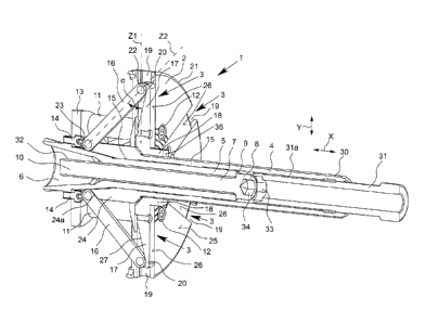
Figs. 1 to 6 show a clamping device 1 with hub centering for the attachment of
a rim
of an automobile wheel (not shown) on a shaft (also not shown) of a balancing
ma-
chine. The clamping device 1 has a contact flange 2 for contacting the rim of
the
automobile wheel and several centering elements 3 moveably guided on the
contact
flange 2 in the radial direction Y for centering engagement in a middle
centering
hole of the rim. Moreover, a clamping sleeve 4 moveably guided in the axial
direc-
tion X relative to the contact flange 2 is provided, with the clamping sleeve
4 and the
centering elements 3 being kinematically coupled such that an axial movement
of the
clamping sleeve 4 leads to a simultaneous coupled movement of all centering
ele-
ments 3 in the radial direction Y.
The clamping device 1 also has a first tube part 5 that can be connected in a
fixed
manner to the shaft of the balancing machine, with an inner cone 6 that is
comple-
mentary to a cone of the shaft of the balancing machine. Using a screw 7 that
ex-
tends in the tube part 5 and abuts with its screw head 8 against an axial
front surface
9 of the tube part 5, the tube part 5 can be connected to the cone of the
shaft of the
balancing machine. For this purpose, the screw 7 is screwed using a wrench
(not
shown) with its threaded end 10 facing away from the screw head 8 into an
internal
thread in the cone of the shaft, thereby holding the tube part 5 firmly on the
shaft.
The contact flange 2 screwed to a ring part 13 by means of spacers 11 and
screws 12,
with the ring part 13 being fixed in turn to the tube part 5 with screws 14,
specifi-
cally on the end of the tube part 5 facing toward the shaft of the balancing
machine
in the middle area of the inner cone 6. The contact flange 2 is connected to
the tube
part 5 so as to be immovable in the axial direction X and in the radial
direction Y.
The clamping sleeve 4 has two slide bearing sections 15, so that the clamping
sleeve
4 is guided on the outer lateral surface of the tube part 5 so as to be
moveable in the
axial direction X.
As can also be seen in Figs. 1 to 6, tension levers 16 are provided for the
kinematic
coupling of the clamping sleeve 4 with the centering elements 3, with each
centering
element 3 being connected in an articulated manner to the clamping sleeve 5 by
CA 02889096 2015-04-21
- 9 -
means of a tension lever 16. The tension levers 16 and the centering elements
3 form
a toggle lever system, with a movement of the clamping sleeve 4 in the axial
direc-
tion X relative to the contact flange 2 leading to a coupled joint
displacement of all
centering elements 3 in the radial direction Y. This can be seen through a
compari-
son of Figs. 1 to 3 and 4 to 6. By virtue of the toggle lever system, the
depicted
clamping device enables the transfer of a high centering force, with the force
applied
against the contact flange 2 when tightening the rim being simultaneously used
for
centering the rim. During tightening of the rim against the contact flange 2,
the
clamping sleeve 4 is pulled in the direction of the rim with a clamping nut
(not
shown), so that the centering elements 3 are displaced outwardly, which
ultimately
leads to the centering and fixing of the rim. It is possible here to center
different rims
with different center hole diameters in a continuously variable manner.
The depicted embodiment of the clamping device 1 has six centering elements 3.
Each centering element 3 is formed by a guide section 17 and a centering
section 18
angled down with respect to the guide section 17 in the axial direction toward
the
rim. The guide sections 17 are moveably guided in T-shaped radial grooves 19
of the
contact flange 2 and have a complementary cross-sectional geometry, so that
the
centering elements 3 are guided on the contact flange 2 so as to be
displaceable in
the radial direction Y and held on the contact flange 2 in the axial direction
X in an
undetachable manner. The centering elements 3 can be moved from a minimum cen-
tering position, which is shown in Figs. 1 and 4, to a maximum centering
position,
which is shown in Figs. 3 and 6, through axial displacement of the clamping
sleeve
4. In the maximum centering position, the ends 20 of the centering elements 17
ex-
tend beyond the circumferential edge 21 of the contact flange 2 outwardly in
the ra-
dial direction. Moreover, upon reaching the maximum centering position, the
center-
ing sections 18 are spaced maximally from the clamping sleeve 4 and adjusted
to a
center hole diameter that is as large as possible.
Each tension lever 16 is connected at its outer end 22 in an articulated
manner to the
end 20 of a centering element 3. At the inner end 23, each tension lever 16 is
hinged
at the rear end of the clamping sleeve 4 and abuts in the minimum centering
position
CA 02889096 2015-04-21
- 10 -
of the centering elements 3 against a bevel 24a of a thickening 24 of the
clamping
sleeve 4. This is shown in Fig. 1. This makes simple displacement and a high
trans-
fer of force possible in the toggle system formed by the tension levers 16 and
the
centering elements 3.
As can be seen from Fig. 1, the clamping angle a between each tension lever 16
and
the respectively coupled centering element 3 can preferably be about 450 when
the
centering elements 3 are arranged in the minimum centering position, i.e., in
the
minimally radially displaced position in the outward direction. It can be seen
from
Fig. 3 that the clamping angle a is preferably about 150 when the centering
element
to 3 is arranged in the maximum centering position, i.e., in the maximally
radially dis-
placed position in the outward direction. Each clamping angle a can be set in
a con-
tinuously variable manner between the abovementioned angular ranges at the
maxi-
mum centering position and minimum centering position of the centering
elements.
In the context of the present disclosure, the clamping angle a respectively
relates to
the middle longitudinal axis Z1 of a centering element 3 and the middle
longitudinal
axis Z2 of a tension lever 16.
As can also be seen from Figs. 1 to 6, flat outer surfaces 26 can be aligned
on the
guide sections 17 and the contact surface 25 of the contact flange 2. The
contact sur-
face 25 and the outer surfaces 26 of the centering elements 3 then abut
jointly against
the rim in the centered fixed state of the rim.
As can also be seen from Figs. 1 to 3, the centering element 3 can have a
chamfer 27
on the side facing away from the rim against which the associated tension
lever 16
comes to rest in the maximum centering position of the centering element 3.
This is
shown in Fig. 3. The tension lever 16 is guided through an oblong opening 28
in the
contact flange 2 and connected at its end 23 to the clamping sleeve 4.
Together, the centering sections 18 of the centering elements 3 form a
cylindrical
outer surface for centering engagement in a middle centering hole of the rim.
In state
in which it is centered and tightened against the contact flange 2, the rim
abuts with
its front side against the contact surface 25 of the contact flange 2, while,
at the same
CA 02889096 2015-04-21
11 -
time, the centering sections 18 embodied as ring segments abut with circular
arch-
shaped outer surfaces 29 against an inner surface of the centering hole.
For the clamping of the rim, a clamping nut is screwed onto an external thread
sec-
tion 30 of the clamping sleeve 4, with the compressive forces causing the
clamping
sleeve 4 to be pulled in the direction of the rim or, in the drawing, to the
right rela-
tive to the contact flange 2, so that the tension levers 16 push the centering
elements
3 radially to the outside until the outer surfaces 29 of the centering
sections 18 abut
in a centering manner against the inner surface of the centering hole.
Within the clamping sleeve 4, a second tube part 31 is provided that can be
moved in
the axial direction X relative to the clamping sleeve 4 and supported against
the first
tube part 5, with the second tube part 31 having an external thread section
31a and
the clamping sleeve 4 having a corresponding internal thread section, and with
the
second tube part 31 being screwed into the clamping sleeve 4. The second tube
part
31 can be screwed by hand into the clamping sleeve 4 in order to enable quick
ad-
justment of the centering elements 3 for presetting to a certain center hole
diameter
of the rim. The second tube part 31 also has a wrench opening 33 at the front-
side
inner end, so that a wrench can be inserted from the outside through the
second tube
part 31 and the wrench opening 33 into an internal hexagon section 34 of the
screw
7. The wrench opening 33 also has a hexagonal contour. If an external thread
32 of
the screw 7 and the external thread section 31a on the second tube part 31
have the
same thread pitch, the screw 7 and the second tube part 31 can be jointly
adjusted in
the axial direction X by means of the wrench.
In order to also enable the tightening and centering of rims with a large
center hold
diameter against the contact flange 2, the distance a is preferably less than
30 mm if
the centering elements 3 are arranged in the maximum centering position
between
the external thread section 30 of the clamping sleeve 4, which preferably
extends to
the thickened area 24, and axial front surfaces 36 on the centering sections
18 of the
centering elements 3 in the axial direction X. This is shown in Fig. 3.