Note: Descriptions are shown in the official language in which they were submitted.
CA 02889098 2015-04-21
MEASURING AND MODIFYING DIRECTIONALITY OF SEISMIC
INTERFEROMETRY DATA
Field of the Invention
The present invention relates to seismic surveying and more particularly to
seismic interferometry.
Background
Seismic surveying techniques use reflected seismic waves to determine
underground geologic structure. One manner of seismic surveying uses an active
source
to generate one or more controlled seismic waves. The active source may, for
example,
be an explosive, an air gun or a vibrator truck. The seismic waves generated
by the
active source are reflected off of underground geologic structure, and the
reflected
seismic waves are typically recorded by a plurality of receivers such as
seismic motion
sensors, geophones, accelerometers, or hydrophones. The recordings may be
vertical
ground motion (velocity or acceleration), pressure, components (e.g. three
directions) of
ground motion or a combination thereof Seismic data processing methods are
then used
to process the recorded response and produce an image of underground geologic
structure
therefrom.
Seismic interferometry is a method of seismic data collection and manipulation
or
processing that is able to use a receiver as a virtual source to simulate and
replace an
active source. Typically, seismic waves are recorded at a primary location
(the virtual
source location). The seismic waves recorded at the primary location may be
deliberate
or non-deliberate seismic waves present in the earth such as, for example,
natural
background seismic waves due to ocean wave action, seismic waves due to
vehicle
traffic, or even seismic waves caused by a remotely positioned active source.
At the
same time, seismic waves are also recorded at at least one additional
location, a
secondary location of the seismic interferometry process. The time series
recorded at the
secondary location is deconvolved using the time series recorded at the
virtual source
location. In instances where the receivers measure multiple components of
ground
CA 02889098 2015-04-21
motion, the deconvolution is performed between each of the components. Since
the
seismic waves recorded at the virtual source location are reflected from the
surface of the
earth, a portion of these reflected seismic waves will reflect off of
underground geologic
structure and reach the additional location. In this regard, the deconvolution
of the
components of the time series recorded at the secondary location contains the
same
response as there would be if there was a source for each of the ground motion
components at the primary location generating seismic waves being recorded by
a
receiver at the additional location. Thus, this seismic interferometry data
may substitute
for conventional active seismic source data. Active source seismic data
processing
methods may then be used to produce an image of underground geologic structure
in a
manner similar to active source seismic surveying.
Summary
The present invention facilitates the use of seismic interferometric
techniques in
determining underground geologic structure. In this regard, one difficulty
with the
seismic interferometric approach is that the seismic wavefield recorded at the
virtual
source often has an undesirable directionality pattern or function. A
directionality
component of the recorded seismic wavefield used for seismic interferometry
(e.g.,
energy coming from one angle and azimuth) can and often does have
significantly
different strength or amplitude than other directionality components of the
seismic
wavefield (e.g., energy coming from other angles and/or azimuths). As a
result, the
virtual source from seismic interferometry will have a non-uniform energy
directionality
pattern or function. This non-uniform energy function may exist for each
ground motion
component. This situation is different from an active source for which the
energy
directionality function is generally well known and often uniform in angle and
azimuth.
The current state of the art of seismic interferometry does not consider the
non-
uniform directionality of the energy at the virtual source and does not
provide for a
method to measure it and correct for it. In this regard, many proposed seismic
interferometric techniques only consider single receivers at the virtual
source location.
2
CA 02889098 2015-04-21
With a single receiver, it is not possible to measure the directionality of
the seismic
energy.
Embodiments described herein present, inter alia, methods to measure and
correct
the non-uniform directionality function of the vibrations recorded at the
virtual source
location when performing seismic interferometry by replacing the single
receiver that
acts as a virtual source with an array of receivers, which will usually be two
dimensional
(2D), but may be one dimensional (1D). The use of an array of receivers at the
virtual
source location allows for measuring the strength of the non-uniform
directionality
function of the seismic energy recorded at the virtual source location by
applying beam
forming or related methods on the array to transform the data into different
directionality
components.
After the strength of the directionality components is measured,
multiplication
factors can be determined to change the directionality component strengths to
produce a
desired directionality function. The multiplication factors may, for example,
be
determined by dividing the desired strength of a directionality component with
the
measured strength. This may be performed subject to damping criteria and
tapering.
The multiplication factors may then be applied by adjusting the strength of
the
directionality components in one of several ways in either the seismic
interferometry
operation or in the conventional seismic data processing. The measurement of
the
directionality components, the determination of the multiplication factors,
and the
application of the multiplication factors can be performed for each ground
motion
component.
Embodiments described herein enable the non-uniform directionality of seismic
energy received at a virtual source during a seismic interferometry process to
be
measured and corrected for in later processing. This may result in a more
accurate
geologic survey than could be accomplished using known seismic interferometry
processes. In this regard, the embodiments described herein may enable
expanded use of
interferometric virtual source methods, which has several advantages over
traditional
active source seismic surveying. For example, since receivers are less
expensive than
active seismic sources, there may be a cost savings involved with replacing an
active
3
CA 02889098 2015-04-21
source with an array of receivers. Furthermore, the potential for
environmental damage
and the risks associated with explosives and heavy machinery inherent in the
use of an
active source can be avoided, or at least mitigated by positioning the active
source in a
less sensitive area. Also, receivers may be easier to place in difficult
locations, such as
hilly terrain or in populated areas.
According to an aspect, a method of performing seismic interferometry to
obtain
information related to subsurface structure includes positioning a plurality
of seismic
receivers to receive seismic waves, using at least one of the seismic
receivers as a
secondary location receiver for seismic interferometry, recording a time
series of seismic
waves incident on each seismic receiver, and modifying a directionality
function of the
virtual source for seismic interferometry.
The positioning may include arranging at least a portion of the plurality of
seismic
receivers in an array within an area associated with a location of a virtual
source for
seismic interferometry. The seismic receivers may be distributed in a uniform
or non-
uniform manner over the area. The positioning and quantity of seismic
receivers may be
at least partially dependent on the surface wavelength corresponding to the
lowest and
highest frequency seismic waves to be recorded. Seismic receivers used as a
secondary
location receiver for seismic interferometry may be among the portion of the
plurality of
seismic receivers arranged in the array or they may be separate from the
portion of the
plurality of seismic receivers arranged in the array.
Modifying the directionality function may involve combining at least two of
the
time series from the seismic receivers included in the array. The combining
may include
performing a spatial domain transform over the array locations of the time
series of
seismic waves incident on each seismic receiver of the array. This transform
may
separate the seismic waves incident on the array into different directionality
components.
Each directionality component may correspond to a value of the directionality
function.
Multiplication factors, time shifts, and phase shifts may be applied to the
data
traces from at least two of the individual receivers of the array. The
multiplication
factors may be applied in the transform domain or equivalent ones may be
applied in the
spatial domain of the original data. Additionally, the multiplication factors
may be
4
CA 02889098 2015-04-21
applied by electronically joining the receivers in the field. Further, the
multiplication
factors may be applied when performing a seismic migration, an imaging, an
inversion
process or a combination thereof. Regardless of how they are applied, the
multiplication
factors may be used to obtain a uniform directionality function or an
intentionally non-
uniform directionality function.
According to an aspect, a method of modifying a directionality function of a
virtual source used in seismic interferometry includes recording seismic wave
data
incident on each individual seismic receiver of an array of seismic receivers,
performing
a domain transform on the recorded seismic wave data to separate the recorded
seismic
wave data into different transform components, measuring a signal strength
measurement
for each transform component, and determining multiplication factors to
convert the
measured signal strength for each transform component into a desired strength
for each
transform component. The virtual source for the seismic interferometry may be
associated with the array of seismic receivers where each receiver of the
array has an
associated location within the array. The determination of the multiplication
factors may
include dividing the desired strength for each individual transform component
by the
measured signal strength for each individual transform component.
According to an aspect, a seismic interferometric system operable to obtain
information related to subsurface structure includes a plurality of seismic
receivers, at
least one recording device operable to record a time series of seismic waves
incident on
each of the plurality of seismic receivers, and a processor operable to modify
a
directionality function of the virtual source for seismic interferometry. The
plurality of
seismic receivers may be positionable such that a portion of them may be
arranged in an
array within an area associated with a location of a virtual source for
seismic
interferometry. At least one of the plurality of seismic receivers may be used
as a
secondary location receiver for seismic interferometry. Modifying the
directionality
function may involve combining at least two of the time series from the
seismic receivers
included in the array.
The processor may be further operable to perform a spatial domain transform
over
the array locations of the time series of seismic waves incident on each
seismic receiver
5
CA 02889098 2015-04-21
of the array. In this regard, the processor may be operable to separate the
recorded
seismic wave data into different transform components. Each of these transform
components may correspond to a type of wave that has some directionality. The
processor may further be capable of measuring a signal strength measurement
for each
transform component and determining multiplication factors to convert the
measured
signal strength for each transform component into a desired strength for each
transform
component.
According to an aspect, a computer program product includes a computer usable
medium having computer program code embedded therein. The computer program
code
may include computer readable program code that may enable a processor to read
a data
file including a time series of seismic waves incident on each seismic
receiver of an array
of seismic receivers, read a data file including a time series of seismic
waves incident on
a secondary location receiver for seismic interferometry, and modify a
directionality
function of a virtual source for seismic interferometry. The array may be
associated with
a location of a virtual source for seismic interferometry. The modifying of
the
directionality function may involve combining at least two of the time series
from the
seismic receivers included in the array. Moreover, the computer readable
program code
may enable the processor to perform a spatial domain transform over the array
locations
of the time series of seismic waves incident on each seismic receiver of the
array. This
transform may separate the time series of seismic waves incident on each
seismic
receiver of the array into different directionality components, where each
directionality
component may correspond to a value of the directionality function.
Additional aspects and corresponding advantages of the present invention will
be
apparent to those skilled in the art upon consideration of the further
description that
follows.
Brief Description of the Drawings
Figure 1 A is a cross sectional schematic view of a seismic sensor placed on
the
Earth's surface and a set of sample seismic directionality components with
different
amplitudes incident upon the seismic sensor.
6
CA 02889098 2015-04-21
Figure 1B is a cross sectional schematic view of the sensor of Figure 1A and
reflected directionality components with different strengths.
Figure 2 is a partial cross sectional schematic view of a set of sensors
placed on
the Earth's surface.
Figures 3A, 3B and 3C are top schematic views of exemplary sensor arrays.
Figures 4A and 4B are cross sectional schematic views of the sensor of Figure
lA
and reflected directionality component vectors after modification.
Figure 5 is a flowchart for one embodiment of a method of performing seismic
interferometry.
Figure 6 is a flowchart for one embodiment of a method of modifying a
directionality function of a virtual source used in seismic interferometry.
Figure 7 is a block diagram of one embodiment of a system operable to obtain
and
store seismic data, modify a directionality function of a virtual source and
perform
seismic interferometry.
Detailed Description
As noted above, seismic interferometry utilizes seismic energy incident upon a
particular location as a virtual source of seismic waves for a seismic survey.
Figure 1A is
a cross sectional schematic view showing a receiver 101 placed on the Earth's
surface
102 at a particular location 104. A plurality of seismic directionality
components
(referred to herein alternatively as directionality components) incident at
the receiver 101
are represented by directionality component vectors 103a through 103g. A
seismic
directionality component is the portion of the seismic waves incident on the
receiver from
a specific direction. As illustrated, the seismic directionality components
incident at
location 104 may be non-uniform, and the varying size of the illustrated
directionality
component vectors 103a through 103g represents the varying amplitudes of
directionality
components incident at the location 104. These directionality components are
separate
for each ground motion component recorded at the receiver.
When performing seismic interferometry using data that has not been modified
or
filtered to take into account the non-uniformity of the directionality
components incident
7
CA 02889098 2015-04-21
at the virtual source location, the non-uniformity of the directionality
components may
distort the geologic image resulting from the seismic data processing and may
amplify
the noise in the data. This noise may result in a degraded image of the
geologic structure
after processing relative to an image that can be obtained from the data if
the non-
uniformity of the directionality components is reduced or eliminated.
However, a single receiver, such as receiver 101 illustrated in Figure 1A, is
not
capable of measuring the non-uniformity of the directionality components
incident at
location 104. If the non-uniformity of the directionality components is not
known, the
data collected cannot be corrected for the non-uniformity.
Embodiments of the present invention facilitate eliminating or reducing
effects
from the non-uniformity of directionality components incident at the location
of a virtual
source used in seismic interferometry. This may be achieved by using an array
of
receivers to record seismic waves incident at the virtual source location of
seismic
interferometry while at the same time recording, with an individual receiver,
seismic
waves incident at the secondary location of seismic interferometry.
Additionally, and at
the same time, other individual receivers may be recording seismic waves
incident at
additional secondary locations. Moreover, individual receivers located in the
array may
be used as part of the virtual source array and as a secondary location for
seismic
interferometry.
The receivers may be operable to record multiple ground motion
components and each ground motion component may be treated separately.
The data collected at the array may be spatially transformed into a different
domain where each transform component of the new domain corresponds to an
approximate directionality of the seismic energy.
The non-uniformity of the
directionality components may then be measured. Multiplication factors may
then be
determined that modify the non-uniform recorded directionality components
into, for
example, uniform components or components with a deliberate desired non-
uniform
distribution that improve the final processed image. The multiplication
factors may be
applied in a number of manners and at different stages of seismic data
processing
including as described herein. This process of measuring the strength of
directionality
8
CA 02889098 2015-04-21
components, determining multiplication factors, and modifying the
directionality function
can be performed separately for each ground motion component.
The application of the multiplication factors may result in a seismic
interferometry signal without the effect of the non-uniform strength of the
directionality
components. The resulting virtual source may simulate an active source with a
uniform
energy distribution over all directionality components or a source with a
deliberate non-
uniform energy distribution that boosts desired directionality components and
damps
undesirable directionality components.
As noted above, an array of receivers may be used to collect seismic data from
which directionality components may be determined. An exemplary arrangement is
illustrated in Figure 2. In Figure 2, an array 201 of receivers is positioned
on the Earth's
surface 203 in an area 202, which is the virtual source location of seismic
interferometry.
Each individual receiver of the array 201, such as receiver 204a may be
capable of
obtaining a time series recording of seismic activity at its location.
Generally, the array 201 may be one dimensional (e.g. a single row of
receivers)
or two-dimensional (e.g., multiple rows and columns of receivers) and the
individual
receivers of the array 201 and individual receivers outside of the array, such
as individual
receivers 205 and 206, may be located at or near the surface 203. As used
herein, the
terms "one-dimensional" and "two-dimensional" may include arrays where one or
more
of the individual receivers of the array 201 are located at different
altitudes with respect
to other receivers in the array (e.g., one individual receiver of the array
201 may be
located on a hillside at a higher elevation than another individual receiver
located deep in
a valley). However, no two individual receivers within array 201 occupy the
same
latitude and longitude. In this regard, if the positions of the individual
receivers of the
array 201 were indicated on a two-dimensional map of the surface 203, no two
indications of the locations of individual receivers would occupy the same
space. In
instances where a body of water covers the Earth's surface at the location
where the
receiver is to be placed, the receiver may be placed at the bottom of the body
of water
(e.g., on the sea floor). Further, it is possible for one or more of the
receivers in array 201
to be buried.
9
CA 02889098 2015-04-21
The arrangement of the receivers in the array 201 may be configured to achieve
particular characteristics and/or accommodate local terrain. For example, an
array 301 in
which the receivers are uniformly distributed throughout an area encompassed
by the
array 301, such as that illustrated in Figure 3A, may be utilized. The overall
size of the
uniform array 301 may be selected based on a surface wavelength corresponding
to the
minimum frequency to be recorded. The spacing between the individual receivers
of the
uniform array 301 may be selected based on a surface wavelength corresponding
to the
maximum frequency to be recorded. The number of receivers may be selected
based on
the bandwidth between the lowest and highest frequencies to be recorded.
The individual receivers may also be non-uniformly distributed as illustrated
in
the exemplary array 302 of Figure 3B. In the non-uniform array 302, the
spacing
between individual receivers of the array 302 along the outer edges of the
array 302 is
greater than the spacing between the individual receivers of the array 302
toward the
center of the array 302. In such an arrangement, the minimum and maximum
distances
between individual receivers of the array 302 may be based on the maximum and
minimum frequencies, respectively, of directionality components to be
measured.
The individual receivers may also be randomly or partially randomly
distributed
as illustrated in the exemplary array 303 of Figure 3C. Such an arrangement
may be
partially dictated by local topography, buildings, or other land and
habitation features.
For example, rough terrain may preclude or make extremely difficult the
formation of
arrays such as those illustrated in Figures 3A and 3B. Many other arrangements
of the
individual receivers within the array are possible in addition to the
arrangements
illustrated in Figures 3A-3C.
Referring again to Figure 2, the array 201 may be used to record data,
determine
directionality components, and compute multiplication factors. The array may
also be
used as a virtual source that applies the multiplication factors to modify the
directionality
components for an interferometric seismic survey. An individual receiver
located outside
of the array 201, such as receivers 205 and 206, may function as a secondary
receiver for
the seismic interferometric survey. Moreover, one or more of the individual
receivers of
the array 201 may function as both a member of the array 201 for purposes of
CA 02889098 2015-04-21
directionality component modification and as a secondary receiver used for
seismic
interferometry.
The data recorded by the array 201 may consist of a separate time series
recorded
by each individual receiver of the array 201. This data may be used to
determine the
amplitude and directionality of seismic directionality components incident on
the area of
the array 201. The amplitude and directionality determination may be
accomplished
using any of a variety of spatial transform methods that transform the data
over the
receiver locations into directionality components. This transform may be
accomplished
by combining at least two of the time series recorded by individual receivers
of the array
201. For example, 1D or 2D slant stacks, 1D or 2D beam forming, and/or 1D or
2D Fast
Fourier Transforms (FFTs) may be employed to determine the amplitude and
directionality of seismic directionality components from the data recorded by
the array
201. Other methods, such as Radon, discreet cosine, Gabor and Wigner
transforms may
also be utilized. Variations of the above-mentioned methods may also be
utilized. All
these transforms, and others, share the property that they mathematically
combine two or
more traces to produce the transformed data. Whatever process is used, uneven
weighting and/or tapering may be employed during the process. Time shifts may
be
applied before the transform to correct for the deviations of the receiver
locations from a
flat surface. The recorded data may be converted from the time domain to
another
domain, such as the frequency domain, prior to performing the spatial
transform to
determine and modify directionality components. This process can be applied
for each
ground motion component.
Once the array data is transformed into directionality components, the total
energy
for each directionality component may be measured. Other signal strength
measurement
techniques may also be utilized. The measurement may be a single measurement
for
each directionality component direction or it can be multiple measurements for
each
directionality component direction for the different data components of each
trace
domain, such as a time window or frequency.
An alternative way of measuring signal strengths of directionality components
without performing a transformation is to apply a set of multiplication
factors, time shifts,
11
CA 02889098 2015-04-21
and phase rotations to the untransformed data, sum the data, and measure
signal strength
from the result. The set of multiplication factors, time shifts, and phase
rotations are
performed to emphasize and possibly isolate one or more directionality
components.
Then the process is repeated with a different set of multiplication factors,
time shifts, or
phase rotations for a different directionality component or group of
directionality
components.
The measured directionality components may be used to compute the
multiplication factors or to modify the directionality components of a virtual
source at the
location 202 of the array 201 for use in a seismic survey using seismic
interferometry
methods (a seismic interferometry survey). The directionality components
(e.g.,
represented by directionality component vectors 103a through 103g in Figure
1A) may be
determined as described herein. To use this information to modify the
directionality
components of a virtual source in seismic interferometry, it may be assumed,
as
illustrated in Figure 1B, that the Earth's surface 102 is a perfect reflector
of the
directionality components. For example, directionality component vector 105f
represents
a directionality component vector that is a reflection of directionality
component vector
103f shown in Figure 1A. Similarly, each directionality component vector 105a
through
105g of Figure 1B represents a reflection of the directionality component
vectors
illustrated in Figure 1A. Once the time series data received at the virtual
source array has
been transformed into separate directionality components, the amplitude of the
directionality components can be modified with multiplication factors before
further
processing. The multiplication factors can be explicitly applied to each
directionality
component or implicitly during further manipulation of the data, such as
active source
seismic processing.
As shown in Figure 2, one or more portions of one or more of the reflected
directionality components (e.g. represented by directionality component
vectors 105a
through 105g in Figure 1B) may be transmitted through the Earth from the first
location
202 to the locations(s) of the additional receivers 205 and 206. Such
reflected seismic
waves are represented by dashed arrows 207a through 207c in Figure 2, and as
shown,
some seismic waves (e.g. 207a) may remain in near surface waveguide structure
208.
12
CA 02889098 2015-04-21
Other seismic waves (e.g. 207b and 207c) may penetrate deeper structure 209
with some
(e.g. 207b) being refracted toward the additional receivers 205 and 206 and
some (e.g.
207c) being reflected at a boundary between deeper structure 209 and one or
more still
deeper structures 210a through 210c.
The determined multiplication factors that are applied to the directionality
components may be used to control a directionality function of the virtual
source used in
seismic interferometry. As previously noted, known methods of performing
seismic
interferometry do not take into account the non-uniform strengths of the
seismic waves
with different directionality incident at the virtual source. As such, image
distortion and
noise may be at higher levels relative to an active source seismic survey when
using
known seismic interferometry methods. This distortion and noise may be reduced
or
eliminated by modifying the directionality function of the virtual source. For
example,
the directionality of the virtual source may be controlled to produce a
uniform
directionality similar to uniform seismic waves generated by active sources.
The
resultant uniform directionality function may be represented by uniform
directionality
component vectors such as directionality component vectors 401a through 401g
of Figure
4A. These directionality components are separate for each ground motion
component.
Other desired directionalities of the virtual source may be utilized. For
example,
if it is desired to reduce noise in the collected data due to seismic waves
traveling near
the surface (e.g., waves such as wave 207a of Figure 2), the strength of waves
reflected at
the virtual source and traveling close to parallel with the Earth's surface
(such as waves
105a and 105g of Figure 1B) may be deemphasized, while directionality
components
traveling at or near perpendicular to the Earth's surface (e.g., waves 105c
and 105d of
Figure 1B) may be emphasized. Such a non-uniform directionality function may
be
represented by the directionality component vectors 402a through 402g of
Figure 4B.
Since near surface seismic waves may introduce noise into data collected
during a
seismic survey, using a directionality function such as that illustrated in
Figure 4B may
serve to reduce the noise level and subsequently improve image quality and
reduce the
amount of processing needed in performing seismic interferometry with the
collected
data. Still other directionality functions may be created. For example, other
functions
13
CA 02889098 2015-04-21
may be generated to emphasize particular ray paths, such as refraction or
reflection ray
paths through a particular layer or section of the geologic structure being
examined.
Also, a directionality function may be selected to compensate for certain
geologic
structure or to emphasize near surface seismic waves.
Creating a desired directionality function may include determining
multiplication
factors that may then be applied to modify the measured directionality
function to the
desired function. For example, multiplication factors may be determined by
dividing the
desired strength for a particular directionality component by the measured
strength for
that particular directionality component as described herein in connection
with FIGS. 4A
& 4B. In instances where the measured strength of a particular directionality
component
is below a predetermined threshold, the measured strength may be increased to
a value
exceeding that threshold prior to the determination of the multiplication
factor. In this
manner, dividing the desired strength by a relatively small measured strength
(and the
corresponding large multiplication factor) that may be unreliable can be
avoided.
Where it is desired that the virtual source be a directionally uniform source,
the
same desired strength may be used in determining each multiplication factor.
Where it is
desired that the virtual source be a directionally non-uniform source, the
desired strength
used in determining various multiplication factors may vary (e.g., to produce
the non-
uniform functions previously discussed).
Other methods may be used to measure the directionality components of a
virtual
source used to either compute the multiplication factors or apply the
multiplication
factors. In a first example, damping factors may be applied to certain
measured
directionality components (e.g., directionality components traveling parallel
to the
Earth's surface). In a second example, measurements made at a subset of
receivers of the
array may be modified prior to determination of directionality components
(e.g., the array
readings may be tapered toward the edges of the array).
The processing described above in relation to data generated by the receivers
of
the array may be performed on the entire recorded time series. Alternatively,
one or
more of the recorded time series may be subdivided into time window subsets
and these
14
CA 02889098 2015-04-21
subsets may be processed as described herein. This may include independently
determining multiplication factors for each time window.
In instances where the data from the receivers of the array are converted into
a
derivative domain of the time domain, multiplication factors may be separately
determined and applied for each value in the derivative domain of the time
domain. For
example, where the derivative domain of the time domain is the frequency
domain,
multiplication factors may be separately determined for each frequency value
and each
directionality component.
Once determined, the multiplication factors may be utilized in a variety of
ways to
enhance a seismic interferometry process. The multiplication factors may have
a number
of characteristics. For example, the multiplication factors may be non-
unitary, and the
multiplication factors may be complex numbers.
Moreover, the multiplication factors may be applicable over a wide geographic
region, possibly hundreds of miles wide. The array used to determine the
multiplication
factors can be different than the array used to apply the multiplication
factors. In this
regard, once a particular set of multiplication factors are determined for a
particular
region, that set of multiplication factors may be used to modify the
directionality function
of a plurality of virtual source arrays for seismic interferometry in that
same region.
Multiplication factors may be applied in a variety of domains and during
different
steps or stages in the processing of the data in order to modify the virtual
source
directionality function. The multiplication factors can be applied early in
the
interferometry processing, or later in the active source seismic data
processing/inversion
step. The multiplication factors can be applied in a spatial transform domain
or they can
be applied in the untransformed domain when the multiplication factors may
correspond
to time shifts or phase rotations. A common trait of these methods is that
they modify
the directionality function of the virtual source by combining two or more
traces from the
receivers in the array.
One method for applying the multiplication factors to the virtual source is to
transform the data recorded from the individual receivers of the array into
the same
domain from which the multiplication factors are computed. Then the
multiplication
CA 02889098 2015-04-21
factors can be directly applied by multiplying the appropriate components in
the
transform domain. Then the data can be transformed back to its original
spatial and time
domain and the data can be further processed with standard interferometric
techniques
and active source seismic processing techniques. Or, instead of transforming
the data
back to the original spatial and time domain, the data can be converted
straight into a
different domain used by the subsequent interferometric techniques and seismic
processing techniques. The data from the individual receivers of the array can
be treated
as separate traces in the subsequent interferometric or seismic processing, or
they can be
reduced, combined, or summed into fewer traces. This process can be applied
separately
for each ground motion component where the traces from a single component are
transformed or combined.
Another method for applying the multiplication factors is to transform the
data
into a domain different than that used to compute the multiplication factors.
In this case,
the multiplication factors can be transformed from their original domain to
the same
domain as the seismic data. The transform may involve interpolation from one
function
of directionality representation to another. This transform of the
multiplication factors
can be done directly from one domain to another, or indirectly by inverse
transforming
the multiplication factors to a spatial domain, possibly resampling or
interpolating them
in the spatial domain, and then transforming them to the new domain that is
consistent
with that used for the data.
Alternately, the above methods of applying the multiplication factors in the
transform domain can be applied in later processing, either during the
application of the
interferometry processing, or during different stages of seismic data
processing. The
interferometric processing or the seismic data processing may transform the
array data
into a different domain. The multiplication factors can then be applied in
this domain,
possibly transforming the multiplication factors as described above. For
example, the
data from the individual receivers or the array may go through standard
interferometric
processing to produce data similar to that from conventional active sources.
This data
may then go through active source seismic data processing. Here, active source
seismic
data processing is meant to imply any seismic processing techniques that apply
to
16
CA 02889098 2015-04-21
conventional active source data. These techniques applied to conventional
active source
data may include standard known methods or new inventive methods. As the data
is
processed by active source seismic data processing, it may be transformed into
a different
domain, such as the plane wave domain, or the Tau-P domain, where each
component
corresponds to some directionality. One such technique is plane wave
migration. When
the data is in this domain, the multiplication factors can be applied to
modify the strength
of the directionality components. This process can be applied separately for
each ground
motion component where the traces from a single component are transformed or
combined together.
This application of multiplication factors during active source processing can
be
performed explicitly, as stated above, by transforming the data into
directionality
components and modifying their strengths, or it can be performed implicitly.
One
approach of applying the multiplication factors implicitly is by performing a
migration,
an imaging, or an inversion process, such as reverse time migration, that
simulates a
source. Normally this source simulation is done with a point source that has a
uniform
directionality function. By simulating a source with non-uniform
directionality function,
the multiplication factors can be applied implicitly. One can produce the non-
uniform
simulated source directionality function that corresponds to the
multiplication factors by
taking the original uniform source, possibly extending it over a larger
region,
transforming it into the same domain as the multiplication factors, apply the
multiplication factors, and then transforming back to the original domain.
Conversely,
one can transform the multiplication factors to the same domain as the
simulated source.
The simulated source can use multiple ground motion components, each with a
different
directionality function.
A special case of applying the multiplication factors in a different domain
from
where they are computed is to apply the multiplication factors directly in the
spatial
domain. In this way, the multiplication factors can be applied to the data
recorded at the
individual receivers of the array without transforming the data. For example,
the
multiplication factors can be transformed into the spatial domain to produce
multiplication factors, time shifts, or phase rotations at the receiver
locations. This
17
CA 02889098 2015-04-21
transformation may involve some interpolation. These new multiplication
factors, time
shifts, or phase rotations may be applied early in the interferometric process
or later
during active source processing. The data can be summed or partially combined
as part
of the application of the new multiplication factors, time shifts, or phase
rotations. This
process can be applied separately for each ground motion component where the
traces
from a single component are transformed, multiplied, or combined.
Furthermore, the directionality of a virtual source may be modified by
interconnecting the receivers of the array in such a manner that a single
aggregated time
series recorded by the interconnected receivers may be used as a modified
virtual source.
In this regard, the receivers may be electronically interconnected.
Electronic
interconnections among the receivers may be accomplished, for example, by
directly
wiring them together, through wireless links or through a combination of wired
and
wireless connections in such a manner that the interconnection is functionally
similar to
applying multiplication factors, time shifts, phase rotations or a combination
thereof to
produce a virtual source with a desired directionality function.
These and other techniques of modifying the directionality of a virtual source
used in seismic interferometry may be used in place of or in conjunction with
the use of
multiplication factors.
As discussed before, these approaches for applying the multiplication factors
may
performed on the whole data or on subsets from individual receivers or from
individual
directionality components in the spatial transform domain. The multiplication
factors
may be applied in the time domain or a derivative of the time domain, such as
the
frequency domain. The multiplication factors may be different for each subset
or they
may be identical. The subsets can be a time window, an individual frequency
component, or a group of frequencies.
The above examples of the application of multiplication factors at various
stages
of the process of determining underlying geologic structure are exemplary.
Other
mathematically equivalent applications of the multiplication factors are also
intended to
be within the scope of the present invention. Additionally, various ones or
all of the
18
CA 02889098 2015-04-21
above-described methods and/or their mathematical equivalents may be combined
to
modify and/or control the directionality of a virtual source.
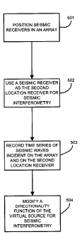
Figure 5 is a flow chart of an embodiment of a method of performing seismic
interferometry to obtain information related to subsurface structure. Although
the flow
chart illustrates the steps in a particular order, this is for exemplary
purposes only and the
order of the steps may be rearranged from that depicted in Figure 5. The first
step 501
illustrated in Figure 5 may be to position a plurality of seismic receivers in
an array. The
array may be within an area associated with the location of a virtual source
for seismic
interferometry.
The next step 502 may be to use a seismic receiver as a secondary location
receiver for seismic interferometry. This secondary location receiver may be
one of the
receivers of the array or it may be a seismic receiver that is not part of the
array. The
secondary location receiver may be colocated within the area of the array or
it may be
located remote from the array (e.g., such as receiver 205 of Figure 2).
The following step 503 may be to use the seismic receivers (e.g., the
receivers of
the array and the secondary location receiver) to record seismic waves
incident on the
seismic receivers. This recording may take the form of a separate time series
for every
individual seismic receiver used. Alternatively, some or all of the outputs of
the seismic
receivers may be combined prior to recording. For example, each of the seismic
receivers of the array may be electrically interconnected and a single time
series for the
entire array may be recorded.
The next step 504 may be to modify a directionality function of the virtual
source
for seismic interferometry. This may involve combining at least two of the
time series
from the seismic receivers included in the array. This combining may be
performed after
the time series have been recorded by, for example, a computer processor and
computer
program product. This combining may involve performing mathematical operations
on
the output signals of the seismic receivers of the array prior to combining
the outputs and
recording a single time series for the array.
Figure 6 is a flow chart of an embodiment of a method of modifying a
directionality function of a virtual source used in seismic interferometry.
Although the
19
CA 02889098 2015-04-21
flow chart illustrates the steps in a particular order, this is for exemplary
purposes only
and the order of the steps may be rearranged from that depicted in Figure 6.
The first
step 601 illustrated in Figure 6 is to record seismic wave data incident on
each seismic
receiver of an array of seismic receivers. The virtual source may be
associated with the
area in which the array of seismic receivers is located.
The following step 602 may be to perform a domain transform on the recorded
seismic wave data of step 601. This domain transform may be performed over the
locations of the receivers of the array. The domain transform may separate the
recorded
seismic wave data into different transform components (e.g., different
directionality
components). This may be followed by step 603 in which a signal strength for
each
transform component is measured.
The next step 604 may be to determine multiplication factors where the
multiplication factors are operable to convert the measured signal strength
for each
transform component into a desired signal strength for each transform
component. The
multiplication factors may be determined as described herein.
Figure 7 is a block diagram of a system 700 operable to perform seismic
interferometry. The system 700 may include a plurality of seismic receivers
701. The
plurality of seismic receivers 701 may be arranged in an array or with a
portion of the
seismic receivers in an array and one or more remotely located seismic
receivers. The
seismic receivers 701 may be interconnected to a data recording device 703 via
an
interconnection 702. The interconnection 702 may take several forms. For
example, the
interconnection 702 may be a hardwired link between the seismic receivers 701
and a
data recording device 703. In another example, the interconnection 702 may be
a
wireless link. In a further example, the interconnection 702 may be a virtual
link where
individual seismic receivers are capable of storing data pertaining to seismic
waves
incident on the individual seismic receiver on storage media (e.g., on a
memory card or
data storage disk). The data may then be transferred, via virtual
interconnection 702, to
the data recording device 703 by transferring the recorded data from the
storage media to
the data recording device 703. The interconnection 702 may comprise one or
more of the
foregoing (hardwired, wireless, virtual).
CA 02889098 2015-04-21
The data recording device 703 may be operable to record data (e.g., time
series of
seismic waves incident on each seismic receiver) generated by the seismic
receivers 701
and store it on a data storage device 704. The data may be stored in the data
storage
device 704 in a variety of manners. For example, all of the data generated by
the seismic
receivers 701 may be stored in a single data file such as data file 705. In
another
example, all of the data generated by the seismic receivers of the array may
be stored in a
single data file such as data file 705 and the data generated by the seismic
receiver or
receivers used as secondary location receivers for seismic interferometry may
be stored in
a separate data file such as data file 706. Other data storage configurations,
such as
storing data generated by each individual seismic receiver of the seismic
receivers 701 in
its own data file, may be used.
The data storage device 704 may be interconnected to a processor 707 capable
of
executing a computer program product 708. The computer program product 708 may
include computer program code stored, for example, on a storage medium (e.g.,
memory,
optical disk, hard drive, floppy disk). The computer program code may be
operable to
perform any of the data processing (e.g., transforms, calculations,
migrations) disclosed
herein. In particular, the computer program code may enable the processor 707
to read
one or more of the data files 705, 706 and to control a directionality
function of a virtual
source for seismic interferometry. The modifying of the directionality
function may
involve combining at least two time series from the seismic receivers included
in the
array.
The computer program code may enable the processor to determine the
directionality function incident on the array (e.g., the processor may be
operable to
determine the directionality components). The computer program code may enable
the
processor to determine multiplication factors. The computer program code may
enable
the processor to apply the multiplication factors. The application of
multiplication
factors may take place at various steps of the seismic surveying process as
previously
discussed.
Although the above detailed description generally describes embodiments
related
to methods and apparatuses for modifying directionality of seismic
interferometry data
21
CA 02889098 2015-04-21
with the use of an array, embodiments described herein may be utilized in
other seismic
interferometry applications and in other configurations.
Additional modifications and extensions to the embodiments described above
will
be apparent to those skilled in the art. Such modifications and extensions are
intended to
be within the scope of the present invention as defined by the claims that
follow.
22