Note: Descriptions are shown in the official language in which they were submitted.
CA 02889206 2015-04-22
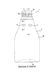
- I -
Double Container
TECHNICAL FIELD
100011 The present invention relates to a double container having a double-
layered structure with an inner layer body and an outer layer body. The inner
layer
is configured to contain a content and accommodated in the outer layer body.
At
the time of dispensing the content, ambient air is introduced between the
outer
layer body and the inner layer body from an air inlet hole to shrink only the
inner
layer body.
BACKGROUND
[0002] As such containers that contain cosmetics such as face lotion,
shampoo,
rinse, liquid soap, food seasoning, or the like, there is known a double
container
that includes an inner layer body having a container portion for containing
the
content and an outer layer body accommodating the inner layer body in a manner
such that the inner layer body is peelable from the outer layer body. The
content is
dispensed by pressing a trunk portion of the outer layer body. After the
pressing is
released, ambient air is introduced between the inner layer body and the outer
layer
body from an air inlet hole provided in a dispensing spout of the outer layer
body,
and as a result, the trunk portion is restored while the volume of the inner
layer
body remains reduced (Refer to Patent Literatures 1 and 2, for example). Since
a
container of this type is capable of dispensing the content without the need
for
replacing the content with ambient air, contact between the content and
ambient air
is limited, and the content is prevented from undergoing deterioration and a
change
in quality.
CITATION LIST
Patent Literature
[0003]
PTL 1: JP2001106263A
PTL 2: JP2006036250A
SUMMARY
[0004] One known example of such a double container is a peelable laminated
container, which is also called delamination container. In this example, the
double
container is configured to have a laminated structure including an outer layer
body
and an inner layer body that are closely joined to each other, for example, by
preparing a laminated parison by co-extruding relatively incompatible
synthetic
Your Ref: S463
Our Ref: P0132603-PCT
(1/35)
CA 02889206 2015-04-22
- 2 -
resins each for the outer layer and the inner layer and by blow molding the
prepared laminated parison with a metal mold. Accordingly, the blow molding is
followed, for example, by shrinking the inner layer body by pumping of air
from
the air inlet hole or by suction of air from the dispensing spout with
negative
pressure, in order to peel the entire inner layer body from the outer layer
body.
Subsequently, air is fed to the inside of the inner layer body to join the
entire inner
layer body closely to the outer layer body again. Thus, at the time of
dispensing
the content, the peeling of the inner layer body from the outer layer body is
facilitated.
[0005] However, in the conventional double container, even when the blow
molding is followed by temporarily peeling the entire inner layer body from
the
outer layer body as described above, the entire outer surface of the inner
layer
body is joined closely to the entire inner surface of the outer layer body
again.
Consequently, at the time of dispensing the content, air is prevented from
entering
between the outer layer body and the inner layer body from the air inlet hole,
possibly resulting in peeling failure of the inner layer body and deformation
of the
outer layer body.
[0006] Patent Literature 2 discloses a container including an outer layer
body
and an inner layer body, wherein a portion of the outer layer body is cut out
to
form an air inlet hole, and a portion of the inner layer body in
correspondence with
the air inlet hole is reversely bulged inward to form an ambient air
introduction
path on an inner periphery of the air inlet hole. Nevertheless, even the
technology
disclosed in Patent Literature 2 does not necessarily ensure smooth peeling of
the
inner layer body from the outer layer body depending on the shape of the
container.
[0007] The present invention has been conceived to solve the aforementioned
conventional problems, and one objective of the present invention is to
provide a
double container that is capable of facilitating the peeling of the inner
layer body
from the outer layer body and preventing the peeling failure of the inner
layer body
and the deformation of the outer layer body at the time of dispensing the
content.
[0008] Another objective of the present invention is to provide a double
container that is capable of facilitating the introduction of ambient air in
use and is
also capable of facilitating the peeling of the inner layer body from the
outer layer
body and that affords a high degree of freedom in the selection of the shape
of the
container.
[0009] One aspect of the present invention resides in a double container,
including: an outer layer body including a tubular dispensing spout and a
trunk
portion that is contiguous with the dispensing spout, the dispensing spout
being
provided in a side portion thereof with an air inlet hole extending through
the
Your Ref: S463
Our Ref.: P0132603-PCT
(2/35)
CA 02889206 2015-04-22
-3 -
dispensing spout from an inside to an outside thereof; and an inner layer body
including an opening, which is contiguous with an opening edge of the
dispensing
spout, and a content container portion, which is contiguous with the opening,
the
inner layer body being accommodated in the outer layer body. The trunk portion
included in the outer layer body is provided with an outer-layer-side
projecting
portion. The inner layer body is provided with an inner-layer-side projecting
portion having a shape that corresponds to an inner surface of the outer-layer-
side
projecting portion. Space is provided between the outer-layer-side projecting
portion and the inner-layer-side projecting portion.
[0010] In the double container according to the first aspect, preferably,
the
inner surface of the outer-layer-side projecting portion that faces to the
side of the
inner layer body has an undercut shape in a longitudinal section thereof in a
direction along an axis of the dispensing spout, and the inner-layer-side
projecting
portion, in a longitudinal section thereof, has the shape that corresponds to
the
inner surface of the outer-layer-side projecting portion.
[0011] In the double container according to the second aspect, preferably,
the
outer-layer-side projecting portion projects toward the inner layer body.
[0012] In the double container according to the third aspect, preferably,
the
trunk portion includes a bottom portion opposing to the dispensing spout, the
bottom portion having a concave shape in which a center side thereof is
depressed
toward the dispensing spout relative to an outer circumferential edge thereof,
and
an outer surface of the outer-layer-side projecting portion that faces to the
opposite
side to the inner layer body has a concave shape including an inclined
surface,
which is inclined closer to the dispensing spout as the inclined surface
extends
further inward of the trunk portion, a flat surface, which is located closer
to the
dispensing spout relative to the inclined surface and which is perpendicular
to the
axis of the dispensing spout, and a cut-out surface, which connects the
inclined
surface and the flat surface and which is depressed toward the dispensing
spout
relative to the flat surface.
[0013] In the double container according to the third aspect, preferably,
an
outer surface of the outer-layer-side projecting portion that faces to the
opposite
side to the inner layer body has a concave shape including a flat surface,
which is
perpendicular to the axis of the dispensing spout, and a curved surface, which
is
located closer to the dispensing spout relative to the flat surface and which
connects to the flat surface.
[0014] In the double container according to the second aspect, preferably,
at
least a portion of the outer-layer-side projecting portion is arranged in a
range
from 60 degrees or more to 90 degrees or less from an axis of the air inlet
hole in a
Your Ref.: S463
Our Ref: P0132603-PCT
(3/35)
CA 02889206 2015-04-22
- 4 -
direction toward a bottom portion included in the trunk portion, in a plan
view
seen from an axis direction of the air inlet hole.
[0015] In the double container according to the first aspect, preferably,
the
outer-layer-side projecting portion includes an outer layer rib extending in a
direction from the dispensing spout to a bottom portion, and an inner surface
of the
outer layer rib that faces to the side of the inner layer body has an undercut
shape
in a transverse section thereof, and the inner-layer-side projecting portion
includes
an inner layer rib that, in a transverse section thereof, has a shape
corresponding to
the inner surface of the outer layer rib.
[0016] In the double container according to the seventh aspect, preferably,
the
outer layer rib, in a transverse section thereof, has a U-shape including a
pair of
side wall portions and a ceiling wall portion that connects the pair of side
wall
portions, and an outer surface of the outer layer rib that faces to the
opposite side
to the inner layer body, in a transverse section thereof, has a shape
including a pair
of outer surfaces of the side wall portions having linear portions which is in
parallel with each other, and a outer surface of the ceiling wall portion
having a
connecting side portion connects the pair of linear portions.
[0017] In the double container according to the eighth aspect, preferably,
the
trunk portion of the outer layer body is further provided with a sub-outer
layer rib
that is adjacent to the outer layer rib, and an outer surface of the sub-outer
layer
rib that faces to the opposite side to the inner layer body, in a transverse
section
thereof, has a shape including an inclined side, which connects to the linear
portion of the outer layer rib and which is inclined relative to the linear
portion.
[0018] In the double container according to the ninth aspect, preferably,
in the
transverse section, the linear portion of the outer layer rib extends
substantially in
parallel with a line that passes a widthwise middle point of the sub-outer
layer rib
and that also passes an axis of the dispensing spout.
[0019] In the double container according to the seventh aspect, preferably,
at
least a portion of the outer layer rib is arranged in a range from 60 degrees
or more
to 90 degrees or less from an axis of the air inlet hole in a direction toward
the
bottom portion, in a plan view seen from an axis direction of the air inlet
hole.
[0020] In the double container according to the first aspect, preferably,
the
outer-layer-side projecting portion includes an outer-layer-side longitudinal
rib
extending in a direction from the dispensing spout to a bottom portion, the
inner-
layer-side projecting portion includes an inner-layer-side longitudinal rib
extending in the direction from the dispensing spout to the bottom portion,
and the
outer-layer-side longitudinal rib and the inner-layer-side longitudinal rib
are
arranged in an area extending in the range of a central angle of 90 downward
from
Your Ref.: S463
Our Ref: P0132603-PCT
(4/35)
CA 02889206 2015-04-22
-5 -
the air inlet hole.
[0021] In the double container according to the twelfth aspect, preferably,
in
each of two areas, one each on left and right sides, determined by excluding
an
area extending in the range of a central angle of less than 600 downward from
the
air inlet hole, from the area extending in the range of a central angle of 90
downward from the air inlet hole, at least a portion of the outer-layer-side
longitudinal rib and at least a portion of the inner-layer-side longitudinal
rib are
arranged.
[0022] In the double container according to the twelfth aspect, preferably,
the
outer-layer-side longitudinal rib is provided in plurality, and the plurality
of outer-
layer-side longitudinal rib includes at least four outer-layer-side
longitudinal ribs,
and
two areas, one each on left and right sides, determined by excluding an area
extending in the range of a central angle of less than 60 downward from the
air
inlet hole, from the area extending in the range of a central angle of 90
downward
from the air inlet hole, communicate to areas defined between two outer-layer-
side
longitudinal ribs in pair.
[0023] According to the present invention, since the trunk portion included
in
the outer layer body is provided with an outer-layer-side projecting portion,
the
inner layer body is provided with an inner-layer-side projecting portion
having a
shape that corresponds to an inner surface of the outer-layer-side projecting
portion, and space is provided between the outer-layer-side projecting portion
and
the inner-layer-side projecting portion, after the inner layer body is peeled
from
the outer layer body, the inner layer is prevented from easily joining closely
to the
outer layer body. Accordingly, space is maintained around the projecting
portions
between the outer layer body and the inner layer body. The space serves as a
flow
path through which ambient air introduced from the air inlet hole flows
between
the outer layer body and the inner layer body at the time of dispensing the
content.
This facilitates the peeling of the inner layer body from the outer layer body
and
prevents the peeling failure of the inner layer body and the deformation of
the
outer layer body in the double container.
[0024] In the present invention, when the inner surface of the outer-layer-
side
projecting portion that faces to the side of the inner layer body has an
undercut
shape in a longitudinal section thereof in a direction along an axis of the
dispensing spout, and the inner-layer-side projecting portion, in a
longitudinal
section thereof, has the shape that corresponds to the inner surface of the
outer-
layer-side projecting portion, after the inner layer body is peeled from the
outer
layer body, the inner-layer-side projecting portion provided in the inner
layer body
Your Ref.: S463
Our Ref.: P0132603-PCT
(5/35)
CA 02889206 2015-04-22
- 6 -
has difficulty fitting into the outer-layer-side projecting portion provided
in the
outer layer body, and the space is maintained around the projecting portions
between the outer layer body and the inner layer body.
[0025] In the above configuration, when the outer-layer-side projecting
portion
projects toward the inner layer body, the aforementioned advantageous effect
is
achieved without compromising the aesthetics of appearance and the operability
of
the double container.
[0026] In the above configuration, when the trunk portion includes a bottom
portion opposing to the dispensing spout, the bottom portion having a concave
shape in which a center side thereof is depressed toward the dispensing spout
relative to an outer circumferential edge thereof, and an outer surface of the
outer-
layer-side projecting portion that faces to the opposite side to the inner
layer body
has a concave shape including an inclined surface, which is inclined closer to
the
dispensing spout as the inclined surface extends further inward of the trunk
portion,
a flat surface, which is located closer to the dispensing spout relative to
the
inclined surface and which is perpendicular to the axis of the dispensing
spout, and
a cut-out surface, which connects the inclined surface and the flat surface
and
which is depressed toward the dispensing spout relative to the flat surface,
the
undercut shape is easily imparted to the inner surface of the outer-layer-side
projecting portion during the blow molding with the metal mold. Furthermore,
when the double container is removed from the metal mold after the blow
molding,
the metal mold is easily released from the outer-layer-side projecting portion
by
displacing the double container upward in accordance with the shape of the
bottom
portion.
[0027] In the above configuration, when an outer surface of the outer-layer-
side
projecting portion that faces to the opposite side to the inner layer body has
a
concave shape including a flat surface, which is perpendicular to the axis of
the
dispensing spout, and a curved surface, which is located closer to the
dispensing
spout relative to the flat surface and which connects to the flat surface, the
undercut shape is easily imparted to the inner surface of the outer-layer-side
projecting portion by the blow molding.
[0028] In the above configuration, when at least a portion of the outer-
layer-
side projecting portion is arranged in a range from 60 degrees or more to 90
degrees or less from an axis of the air inlet hole in a direction toward a
bottom
portion included in the trunk portion, in a plan view seen from an axis
direction of
the air inlet hole, space of the creases arising around the air inlet hole
when the
inner layer body is joined to the outer layer body again after being peeled
from the
outer layer body is allowed to communicate with the space maintained between
the
Your Ref.: S463
Our Ref: P0132603-PCT
(6/35)
CA 02889206 2015-04-22
- 7 -
outer-layer-side projecting portion and the inner-layer-side projecting
portion.
Accordingly, the presence of the air flow path between the air inlet hole and
the
trunk portion is further ensured.
[0029] In the present invention, when the outer-layer-side projecting
portion
includes an outer layer rib extending in a direction from the dispensing spout
to a
bottom portion, an inner surface of the outer layer rib that faces to the side
of the
inner layer body has an undercut shape in a transverse section thereof, and
the
inner-layer-side projecting portion includes an inner layer rib that, in a
transverse
section thereof, has a shape corresponding to the inner surface of the outer
layer
rib, after the inner layer body is peeled from the outer layer body, the inner
layer
rib provided in the inner layer body has difficulty fitting into the outer
layer rib
provided in the outer layer body, and the space is maintained around the ribs
between the outer layer body and the inner layer body.
[0030] In the above configuration, when the outer layer rib, in a
transverse
section thereof, has a U-shape including a pair of side wall portions and a
ceiling
wall portion that connects the pair of side wall portions, and an outer
surface of the
outer layer rib that faces to the opposite side to the inner layer body, in a
transverse section thereof, has a shape including a pair of outer surfaces of
the side
wall portions having linear portions which is in parallel with each other, and
a
outer surface of the ceiling wall portion having a connecting side portion
which
connects the pair of linear portions, at the time of blow molding the
laminated
parison with the metal mold to configure the double container, the laminated
parison is stretched in the metal mold so that the thickness of corner
portions
connecting both the side wall portions and the ceiling wall portion of the
outer
layer rib may be reduced. Thus, the outer layer rib whose inner surface has
the
undercut shape in the transverse section, together with the inner layer rib
having the
shape corresponding to the inner surface of the outer layer rib in the
transverse
section, is easily formed.
[0031] In the above configuration, when the trunk portion of the outer
layer
body is further provided with a sub-outer layer rib that is adjacent to the
outer
layer rib, and an outer surface of the sub-outer layer rib that faces to the
opposite
side to the inner layer body, in a transverse section thereof, has a shape
including
an inclined side, which connects to the linear portion of the outer layer rib
and
which is inclined relative to the linear portion, at the time of blow molding
the
laminated parison with the metal mold, the laminated parison tends to flow
toward
the sub-outer layer rib along the inclined sides. Accordingly, the laminated
parison
is stretched further toward the corner portions connecting both the side wall
portions and the ceiling wall portion of the outer layer rib, allowing deeper
Your Ref.: S463
Our Ref.: P0132603-PCT
(7/35)
CA 02889206 2015-04-22
- 8 -
undercut shapes to be imparted to the transverse sections of the outer layer
rib and
the inner layer rib.
[0032] In the above configuration, when, in the transverse section, the
linear
portion of the outer layer rib extends substantially in parallel with a line
that
passes a widthwise middle point of the sub-outer layer rib and that also
passes an
axis of the dispensing spout, at the time of blow molding the laminated
parison
with the metal mold, the laminated parison is stretched further toward the
corner
portions connecting both the side wall portions and the ceiling wall portion
of the
outer layer rib in the metal mold, allowing deeper undercut shapes to be
imparted
to the transverse sections of the outer layer rib and the inner layer rib.
[0033] In the above configuration, when at least a portion of the outer
layer rib
is arranged in a range from 60 degrees or more to 90 degrees or less from an
axis
of the air inlet hole in a direction toward the bottom portion, in a plan view
seen
from an axis direction of the air inlet hole, space of the creases arising
around the
air inlet hole when the inner layer body is joined to the outer layer body
again after
being peeled from the outer layer body is allowed to communicate with the
space
maintained between the outer layer rib and the inner layer rib. Accordingly,
the
presence of the air flow path between the air inlet hole and the trunk portion
is
further ensured.
[0034] In the present invention, when the outer-layer-side projecting
portion
includes an outer-layer-side longitudinal rib extending in a direction from
the
dispensing spout to a bottom portion, the inner-layer-side projecting portion
includes an inner-layer-side longitudinal rib extending in the direction from
the
dispensing spout to the bottom portion, and the outer-layer-side longitudinal
rib
and the inner-layer-side longitudinal rib are arranged in an area extending in
the
range of a central angle of 90 downward from the air inlet hole, by
undergoing an
initial peeling process, the double container releases the inner-layer-side
longitudinal rib from the fitted state with the outer-layer-side longitudinal
rib,
thereby ensuring that an ambient air introduction path may be maintained on
the
periphery of the outer-layer-side longitudinal rib and the inner-layer-side
longitudinal rib in the trunk portion. Furthermore, the ambient air
introduction
path maintained in the trunk portion of the container communicates with the
air
inlet hole provided in the mouth portion of the container. As a result, the
introduction of ambient air to the trunk portion of the container in use is
facilitated,
and the peeling of the inner layer body from the outer layer body is also
facilitated,
and moreover, the double container affords a high degree of freedom in the
selection of the shape of the container.
Your Ref: S463
Our Ref.: P0132603-PCT
(8/35)
CA 02889206 2015-04-22
- 9 -
BRIEF DESCRIPTION OF THE DRAWINGS
[0035]
FIG. 1 is a front view of a peelable laminated container according to one
embodiment of a double container of the present invention.
FIG. 2 is a sectional view taken along a line A-A in FIG. 1.
FIG. 3A is a sectional view taken along a line B-B in FIG. 1, illustrating a
state of an inner layer body before being peeled.
FIG. 3B is a sectional view taken along a line B-B in FIG. 1, illustrating a
state of the inner layer body after being peeled.
FIG. 4 is a sectional view schematically illustrating a state where the
peelable
laminated container of FIG. 1 is blow molded with a metal mold.
FIG. 5 is a sectional view schematically illustrating how the peelable
laminated container is removed from the metal mold after the blow molding as
illustrated in FIG. 4.
FIG. 6 is a front view of a peelable laminated container according to another
embodiment of the present invention.
FIG. 7A is a sectional view taken along a line C-C in FIG. 6, illustrating a
state of an inner layer body before being peeled.
FIG. 7B is a sectional view taken along a line C-C in FIG. 6, illustrating a
state of the inner layer body after being peeled.
FIG. 8 is a sectional view schematically illustrating a state where the
peelable
laminated container of FIG. 6 is blow molded with a metal mold.
FIG. 9 is a sectional view schematically illustrating how the peelable
laminated container is removed from the metal mold after the blow molding as
illustrated in FIG. 8.
FIG. 10 is a partially cut-away front view of a peelable laminated container
for illustrating a modified example of the arrangement of outer-layer-side
projecting portions in FIG. 1.
FIG. 11 is a front view of a peelable laminated container according to yet
another embodiment of the present invention.
FIG. 12 is a plan view of the peelable laminated container of FIG. 11.
FIG. 13 is a sectional view taken along a line D-D in FIG. 11.
FIG. 14 is a sectional view taken along a line E-E in FIG. 11, with the left
half
of the figure illustrating a state during blow molding, and the right half of
the
figure illustrating a state after peeling.
FIG. 15 is a side view of a peelable laminated container according to yet
another embodiment of the present invention.
Fig. 16A is a sectional view taken along a line F-F in FIG. 15 before an
initial
Your Ref: S463
Our Ref: P0132603-PCT
(9/35)
CA 02889206 2015-04-22
-
peeling process.
Fig. 16B is a sectional view taken along a line G-G in FIG. 15 before the
initial peeling process.
Fig. 17A is a sectional view taken along a line F-F in FIG. 15 after the
initial
peeling process.
Fig. 17B is a sectional view taken along a line G-G in FIG. 15 after the
initial
peeling process.
FIG. 18 is a side view of a peelable laminated container according to yet
another embodiment of the present invention.
Fig. 19 is a sectional view taken along a line G-G in FIG. 18 before the
initial
peeling process.
Fig. 20 is a sectional view taken along a line G-G in FIG. 18 after the
initial
peeling process.
DETAILED DESCRIPTION
[0036] Exemplary embodiments of the present invention will be described in
detail with respect to the drawings.
[0037] As illustrated in FIGs. 1 to 3, a peelable laminated container 1
according
to one embodiment of a double container of the present invention includes an
outer
layer body 2 constituting an outer shell and an inner layer body 3
accommodated in
the outer layer body 2. The peelable laminated container 1, which is also
called
delamination container, is configured to have a laminated structure with the
outer
layer body 2 and the inner layer body 3 that is closely joined to the inner
surface
of the outer layer body 2 in a manner such that the inner layer body 3 is
peelable
from the outer layer body 2, for example, by preparing a laminated parison by
co-
extruding relatively incompatible synthetic resins each for the outer layer
and the
inner layer and by blow molding the prepared laminated parison with a metal
mold.
[0038] The outer layer body 2 has a bottle shape including a tubular
dispensing
spout 2a that has a circular section and a trunk portion 2b that is integrally
contiguous with the dispensing spout 2a and that has a circular section. The
trunk
portion 2b may be flexible enough to be dented when being squeezed and to be
restored to the original shape from the dented state. The trunk portion 2b
also
includes a bottom portion 2c opposing to the dispensing spout 2a. The bottom
portion 2c has a concave shape in which the center side is depressed toward
the
dispensing spout 2a relative to the outer circumferential edge.
[0039] The inner layer body 3 is formed in a bag shape with a smaller
thickness
than the outer layer body 2, and the outer surface of the inner layer body 3
is
joined closely to the inner surface of the outer layer body 2 in a peelable
manner.
Your Ref.: S463
Our Ref: P0132603-PCT
(10/35)
CA 02889206 2015-04-22
- 11 -
The inner layer body 3 includes an opening 3a that is contiguous with the
opening
edge of the dispensing spout 2a included in the outer layer body 2. The inner
layer
body 3 also includes, inside thereof, a container portion 3b that is
contiguous with
the opening 3a. The container portion 3b may contain a liquid content,
including
cosmetics such as face lotion, shampoo, rinse, liquid soap, or food seasoning.
[0040] The dispensing spout 2a of the outer layer body 2 is provided in a
side
portion (an outer circumferential portion) thereof with an air inlet hole 4
extending
through the dispensing spout 2a along a radial direction from an inside to an
outside thereof. The air inlet hole 4 communicates between the outer layer
body 2
and the inner layer body 3, and therefore, when the inner layer body 3 is
peeled
from the outer layer body 2, ambient air is introduced between the outer layer
body
2 and the inner layer body 3.
[0041] The dispensing spout 2a of the outer layer body 2 is configured to
allow
members, such as a dispensing cap provided with a dispensing valve, various
types
of a nozzle, and a dispensing pump, to be mounted thereon. The content is
dispensed through these members. These members may be screwed to a screw
portion 2d, which is provided in the dispensing spout 2a, to be fixed to the
dispensing spout 2a. However, these members may also be fixed by any other
means such as an undercut.
[0042] The peelable laminated container 1 as described above, when a
dispensing cap provided with a dispensing valve is mounted on the dispensing
spout 2a, may dispense the content from the dispensing spout 2a in response to
squeezing of the trunk portion 2b of the outer layer body 2. After the
dispensing of
the content, the outer layer body 2 is restored to the original shape. At this
time,
since ambient air flows between the outer layer body 2 and the inner layer
body 3,
the outer layer body 2 is restored to the original shape while the volume of
the
container portion 3b of the inner layer body 3 remains reduced. Thus, the
dispensing of the content does not cause ambient air to enter from the
dispensing
spout 2a to the inside of the container portion 3b of the inner layer body 3,
and the
content contained in the container portion 3b is prevented from contact with
air,
and therefore, from deterioration. Meanwhile, the content contained in the
container portion 3b may also be dispensed from the dispensing spout 2a by its
own weight, by tilting the outer layer body 2. Furthermore, when a pump is
mounted on the dispensing spout 2a, the outer layer body 2 may be inflexible.
[0043] As illustrated in FIGs. 1 and 2, the trunk portion 2b of the outer
layer
body 2 is provided with a circumferentially arranged pair of outer-layer-side
projecting portions 5 for facilitating the peeling of the inner layer body 3
from the
outer layer body 2 at the time of dispensing the content. The outer-layer-side
Your Ref: S463
Our Ref: P0132603-PCT
(11/35)
CA 02889206 2015-04-22
- 12 -
projecting portions 5 may be integrally formed on the trunk portion 2b by blow
molding with the metal mold. The pair of outer-layer-side projecting portions
5 has
substantially the same structure, and a description is given below only of one
of
the outer-layer-side projecting portions S.
[0044] As illustrated in FIG. 3, the outer-layer-side projecting portion 5
is
provided in the outer layer body 2 to project toward the inner layer body 3,
that is
to say, toward an inside of the peelable laminated container 1 relative to the
outer
circumferential surface of the outer layer body 2. The appearance of the outer-
layer-side projecting portion 5 is in a concave shape that is depressed inward
relative to the outer circumferential surface of the outer layer body 2.
[0045] The outer-layer-side projecting portion 5 includes an upper wall 5a,
a
lower wall 5b, a connecting wall Sc, and a pair of side walls 5d. The upper
wall 5a
extends perpendicularly to an axis of the dispensing spout 2a. The lower wall
5b is
disposed below the upper wall 5a, that is to say, closer to the bottom portion
2c.
The lower wall 5b is inclined closer to the dispensing spout 2a as the lower
wall 5b
extends further inward of the trunk portion 2b, with respect to a direction
that is
perpendicular to the axis of the dispensing spout 2a. The connecting wall Sc
connects the upper wall 5a and the lower wall 5b. The connecting wall Sc is
formed
in a curved shape in which a portion of the connecting wall Sc bulges out
toward
the dispensing spout 2a relative to the upper wall 5a. The side walls 5d
connect to
circumferential end portions of the upper wall 5a, the lower wall 5b, and the
connecting wall Sc to define circumferential end portions of the concave shape
of
the outer-layer-side projecting portion 5. Although FIG. 3 illustrates one of
the pair
of the side walls 5d only, the similar side wall 5d is also provided on the
other end
portion of the outer-layer-side projecting portion 5.
[0046] The upper wall 5a has an outer surface defined as a flat surface 5e
that is
perpendicular to the axis of the dispensing spout 2a. The lower wall 5b also
has an
outer surface defined as an inclined surface 5f that is inclined closer to the
dispensing spout 2a as the inclined surface 5f extends further inward of the
trunk
portion 2b. The connecting wall 5c also has an outer surface defined as a cut-
out
surface 5g that connects the flat surface 5e and the inclined surface 5f and
that is
partly depressed toward the dispensing spout 2a relative to the flat surface
5e. In
the present embodiment, the cut-out surface 5g is formed around a junction
between the upper wall 5a and the connecting wall Sc. In this way, the outer
surface of the outer-layer-side projecting portion 5 that faces to the
opposite side
to the inner layer body 3 includes the flat surface 5e, the inclined surface
5f, and
the cut-out surface 5g.
[0047] On the other hand, the inner surface of the outer-layer-side
projecting
Your Ref.: S463
Our Ref.: P0132603-PCT
(12/35)
CA 02889206 2015-04-22
- 13 -
portion 5 that faces to the side of the inner layer body 3 has an undercut
shape in
the longitudinal section in a direction along the axis of the dispensing spout
2a.
That is to say, the inner surface of the connecting wall Sc of the outer-layer-
side
projecting portion 5 that faces to the side of the inner layer body 3 partly
projects
toward the dispensing spout 2a relative to the upper wall 5a. Thus, the outer-
layer-
side projecting portion 5 has the undercut shape with respect to a direction
that is
perpendicular to the inner surface of the outer layer body 2, that is to say,
a
direction in which the inner layer body 3 is peeled from the outer layer body
2.
[0048] In correspondence with the pair of outer-layer-side projecting
portions 5,
a pair of inner-layer-side projecting portions 6 are provided in the inner
layer body
3. Although FIG. 3 merely illustrates one of the pair of inner-layer-side
projecting
portions 5d in correspondence with the one of the pair of outer-layer-side
projecting portions, the other one of the pair of inner-layer-side projecting
portions
6 is also provided in the inner layer body 3 in correspondence with the other
one of
the pair of outer-layer-side projecting portions 5. The inner-layer-side
projecting
portion 6 projects from the outer circumferential surface of the inner layer
body 3
toward an inside of the inner layer body 3. The inner-layer-side projecting
portion
6, in the longitudinal section, has a shape that corresponds to the inner
surface of
the outer-layer-side projecting portion 5. The outer surface of the inner-
layer-side
projecting portion 6 has a shape that is substantially the same as the shape
of the
inner surface of the outer-layer-side projecting portion 5. As illustrated in
FIG. 3A,
after blow molding, the outer surface of the inner-layer-side projecting
portion 6 is
closely joined to the inner surface of the outer-layer-side projecting portion
5.
[0049] By providing the outer layer body 2 with the outer-layer-side
projecting
portion 5 whose inner surface has the undercut shape, and by providing the
inner
layer body 3 with the inner-layer-side projecting portion 6 whose outer
surface has
the shape corresponding to the undercut shape of the outer-layer-side
projecting
portion 5, the following effect is achieved. That is to say, as illustrated in
FIG. 3B,
once the inner layer body 3 is peeled from the outer layer body 2, the inner-
layer-
side projecting portion 6 provided in the inner layer body 3 has difficulty
fitting
into the outer-layer-side projecting portion 5 provided in the outer layer
body 2
again, and space is maintained between the outer-layer-side projecting portion
5
and the inner-layer-side projecting portion 6. When, for example, the blow
molding
of the peelable laminated container 1 is followed by shrinking the inner layer
body
3 by suction with negative pressure to peel the entire inner layer body 3 from
the
outer layer body 2, and subsequently by pumping air to the inside of the inner
layer
body 3, the space is maintained between the outer-layer-side projecting
portion 5
and the inner-layer-side projecting portion 6 while the remaining portion of
the
Your Ref: S463
Our Ref: P0132603-PCT
(13/35)
CA 02889206 2015-04-22
- 14 -
inner layer body 3 is closely joined to the inner surface of the outer layer
body 2.
Accordingly, at the time of dispensing the content contained in the inner
layer 3
through the dispensing spout 2a, the space maintained between the outer-layer-
side
projecting portion 5 and the inner-layer-side projecting portion 6 serves as
an air
flow path which allows the ambient air introduced from the air inlet hole 4 to
easily flow between the outer layer body 2 and the inner layer body 3 even in
a
portion of the trunk portion 2b that is located near the bottom portion 2c.
This
facilitates the peeling of the inner layer body 3 from the outer layer body 2
and
prevents the peeling failure of the inner layer body 3 and the deformation of
the
outer layer body 2 in the peelable laminated container 1.
[00501 As
described above, the outer surface of the outer-layer-side projecting
portion 5 provided in the outer layer body 2 is formed in the undercut shape
including the flat surface 5e that is perpendicular to the axis of the
dispensing
spout 2a, the inclined surface 5f that is inclined closer to the dispensing
spout 2a
as the inclined surface 5f extends further inward of the trunk portion 2b, and
the
cut-out surface 5g that is depressed toward the dispensing spout 2a relative
to the
flat surface 5e. The above configuration makes it easy to impart the undercut
shape
to the inner surface of the outer-layer-side projecting portion 5 during the
blow
molding of the peelable laminated container 1 with the metal mold. In detail,
as
illustrated in FIG. 4, by providing, in a metal mold 7 used for the blow
molding, a
convex portion 7a having the undercut shape corresponding to the outer surface
of
the outer-layer-side projecting portion 5 and by blow molding the laminated
parison with the metal mold 7, the outer-layer-side projecting portion 5
having the
undercut shape is easily formed. Since the bottom portion 2c of the peelable
laminated container 1 is formed in the concave shape, as illustrated in FIG.
5, after
the blow molding, the metal mold 7 may be opened about a hinge axis (which is
not illustrated) extending along the vertical direction thereof, that is to
say, along
the axis of the dispensing spout 2a, and the peelable laminated container 1
may be
removed from the metal mold 7 by displacing the container 1 upward by moving
the bottom portion 2c along a bottom surface 7b of the metal mold 7. In the
present
embodiment, since the outer surface of the outer-layer-side projecting portion
5 is
formed in the undercut shape extending toward the dispensing spout 2a, that is
to
say, upward, and the flat surface 5e, which defines the outer surface of the
upper
wall 5a of the outer-layer-side projecting portion 5, is formed
perpendicularly to
the axis direction of the dispensing spout 2a, and the inclined surface 5f of
the
lower wall 5b is formed inclined closer to the dispensing spout 2a as the
inclined
surface 5f extends further inward of the trunk portion 2b, the outer-layer-
side
projecting portion 5 may be separated from the convex portion 7a provided in
the
Your Ref: S463
Our Ref: P0132603-PCT
(14/35)
CA 02889206 2015-04-22
- 15 -
metal mold 7 easily after the blow molding. Thus, the peelable laminated
container
1 is easily removed from the metal mold 7.
[0051] FIG. 6 is a front view of a peelable laminated container according
to
another embodiment of the double container of the present invention. In FIG.
6,
members substantially the same as those described above are denoted by the
same
reference numerals.
[0052] The peelable laminated container 1 of FIG. 6 differs from the
peelable
laminated container 1 of FIG. 1 in that the level of raise of the bottom
portion 2c is
lower and in that an outer-layer-side projecting portion 11 has a different
shape as
described below.
[0053] As illustrated in FIG. 7, the outer-layer-side projecting portion 11
of the
peelable laminated container 1 projects toward the inner layer body 3, that is
to say,
toward the inside of the peelable laminated container 1 relative to the outer
circumferential surface of the outer layer body 2. The appearance of the outer-
layer-side projecting portion 11 is in a concave shape that is depressed
inward
relative to the outer circumferential surface of the outer layer body 2. The
outer-
layer-side projecting portion 11 includes a lower wall ha and an upper wall 11
b.
The lower wall ha extends perpendicularly to the axis of the dispensing spout
2a,
and the upper wall 1 lb is formed in a concave shape that connects to an inner
end
of the lower wall 1 la and the outer circumferential surface of the outer
layer body
2. The lower wall ha has an outer surface defined as a flat surface 11c that
is
perpendicular to the axis of the dispensing spout 2a, and the upper wall has
an
outer surface defined as a concave curved surface lid that is located above
the flat
surface 11c of the lower wall 11a, that is to say, closer to the dispensing
spout 2a,
and that connects to the flat surface 11c.
[0054] In this peelable laminated container 1 also, the inner surface of
the
outer-layer-side projecting portion 11 that faces to the side of the inner
layer body
3 has an undercut shape in the longitudinal section in the direction along the
axis
of the dispensing spout 2a. In the present embodiment, a portion of the outer-
layer-
side projecting portion 11 that is located around a junction between an inner
surface of the lower wall ha and the outer circumferential surface of the
outer
layer body 2 has an undercut shape that is depressed upward, that is to say,
toward
the dispensing spout 2a, in the direction that is perpendicular to the inner
surface
of the outer layer body 2, that is to say, the direction in which the inner
layer body
3 is peeled from the outer layer body 2, relative to the remaining portion of
the
lower wall Ila.
[0055] As illustrated in FIG. 8, by providing, in the metal mold 7 used for
the
blow molding, the convex portion 7a having the undercut shape corresponding to
Your Ref: S463
Our Ref: P0132603-PCT
(15/35)
CA 02889206 2015-04-22
- 16 -
the outer surface of the outer-layer-side projecting portion 11, the undercut
shape
is easily imparted to the inner surface of the outer-layer-side projecting
portion 11
with the metal mold 7.
[0056] Furthermore, since the outer surface of the upper wall lib is
defined as
the curved surface 11d, during the blow molding, the laminated parison may be
blow molded in accordance with the shape of the metal mold to impart a deeper
undercut shape to the junction between the lower wall lla and the inner
surface of
the outer layer body 2.
[0057] In correspondence with the outer-layer-side projecting portion 11,
inner-
layer-side projecting portion 12 is provided in the inner layer body 3. The
inner-
layer-side projecting portion 12 projects from the outer circumferential
surface of
the inner layer body 3 toward the inside of the inner layer body 3. The inner-
layer-
side projecting portion 12, in the longitudinal section, has a shape that
corresponds
to the inner surface of the outer-layer-side projecting portion 11. The outer
surface
of the inner-layer-side projecting portion 12 has a shape that is
substantially the
same as the shape of the inner surface of the outer-layer-side projecting
portion 11.
As illustrated in FIG. 7A, after the blow molding, the outer surface of the
inner-
layer-side projecting portion 12 is closely joined to the inner surface of the
outer-
layer-side projecting portion 11.
[0058] Accordingly, the similar effect is also achieved in this peelable
laminated container 1. That is to say, as illustrated in FIG. 7B, once the
inner layer
body 3 is peeled from the outer layer body 2, the inner-layer-side projecting
portion 12 provided in the inner layer body 3 has difficulty fitting into the
outer-
layer-side projecting portion 11 provided in the outer layer body 2 again, and
space
is maintained between the outer-layer-side projecting portion 11 and the inner-
layer-side projecting portion 12.
[0059] As illustrated in FIG. 8, the peelable laminated container 1 is also
configured by blow molding the laminated parison with the metal mold 7
provided
with the convex portion 7a used for forming the outer-layer-side projecting
portion
11. In the present embodiment, since the level of raise of the bottom portion
2c of
the peelable laminated container 1 is lower than that of the peelable
laminated
container 1 of FIG. 1, as illustrated in FIG. 9, even with the outer surface
of the
lower wall ha being defined as the flat surface 11c that is perpendicular to
the
axis of the dispensing spout 2a, the outer-layer-side projecting portion 11
may be
separated from the convex portion 7b provided in the metal mold 7 easily after
the
blow molding. Thus, the peelable laminated container 1 is easily removed from
the
metal mold 7.
[0060] FIG. 10 is a partially cut-away front view of a double container for
Your Ref.: S463
Our Ref: P0132603-PCT
(16/35)
CA 02889206 2015-04-22
- 17 -
illustrating a modified example of the arrangement of the outer-layer-side
projecting portions of FIG. I.
[0061] In the modified example of FIG. 10, portions of the two outer-layer-
side
projecting portions 5 provided in the outer surface of the outer layer body 2
are
arranged in a range from 60 degrees or more to 90 degrees or less from an axis
of
the air inlet hole 4 downward in a direction that passes the center of the air
inlet
hole 4 and that is parallel to the axis of the dispensing spout 2a, in a plan
view
seen from an axis direction of the air inlet hole 4.
[0062] When the inner layer body 3 is joined to the outer layer body 2
again
after being temporarily peeled from the outer layer body 2 after the blow
molding
as described above, the inner layer body 3 closely joined to the outer layer
body 2
is creased around the air inlet hole 4 provided in the dispensing spout 2a,
and
space of the creases arises between the outer layer body 2 and the inner layer
body
3 in a direction from the air inlet hole 4 to the trunk portion 2b. Such space
often
arises in the range from 60 degrees to 90 degrees from the axis of the air
inlet hole
4 in the direction toward the trunk portion 2b. Accordingly, arranging the
outer-
layer-side projecting portions 5 in the aforementioned range allows the space
of
the creases arising around the air inlet hole 4 to communicate with the space
maintained between the outer-layer-side projecting portions 5 and the inner-
layer-
side projecting portions, thereby further ensuring the presence of the air
flow path
between the air inlet hole 4 and the trunk portion 2b. In the illustrated
example, the
portions of the outer-layer-side projecting portions 5 are arranged in the
range
from 60 degrees or more to 90 degrees or less from the axis of the air inlet
hole 4
in the direction that passes the center of the air inlet hole 4 and that is
parallel to
the axis of the dispensing spout 2a. However, any other arrangement may be
possible if only at least portions of the outer-layer-side projecting portions
5 are
arranged in the aforementioned range so that the communication flow path may
be
formed between the air inlet hole 4 and the trunk portion 2b. For example, the
entire outer-layer-side projecting portions 5 may be arranged in the
aforementioned
range.
[0063] Needless to say, the present invention is not limited to the above
embodiments, and various changes may be made without departing the gist of the
present invention. For example, although in the above embodiments the
dispensing
spout 2a is provided with the single air inlet hole 4, and the outer layer
body 2 is
provided with the pair of outer-layer-side projecting portions 5, 11 in
correspondence with the air inlet hole 4, the dispensing spout 2a may be
provided
with a plurality of air inlet holes 4, and the outer layer body 2 may be
provided
with a plurality of pairs of outer-layer-side projecting portions 5, 11 in
Your Ref.: S463
Our Ref: P0132603-PCT
(17/35)
CA 02889206 2015-04-22
- 18 -
correspondence with the air inlet holes 4. Alternatively, the dispensing spout
2a
may be provided with a plurality of air inlet holes 4, and the outer layer
body 2
may be provided with the outer-layer-side projecting portions 5, 11 in
correspondence with at least one of the air inlet holes 4.
[0064] Furthermore, the outer surfaces of the outer-layer-side projecting
portions 5, 11 may have any other shapes that allow the undercut shapes to be
imparted to the inner surfaces of the outer-layer-side projecting portions 5,
11 in
the longitudinal sections.
[0065] Moreover, the outer-layer-side projecting portions 5, 11 do not need
to
be shaped to project toward the inner layer body 3 relative to the outer layer
body
2 and may be shaped to project outward, that is to say, toward the opposite
side to
the inner layer body 3 relative to the outer layer body 2.
[0066] Moreover, the double container of the present invention is not
limited to
the peelable laminated container 1 including the outer layer body 2 and the
inner
layer body 3 that are integrally configured by blow molding the laminated
parison.
The double container may also be configured by forming the outer layer body 2
and the inner layer body 3 separately and subsequently incorporating the inner
layer body 3 into the outer layer body 2.
[0067] With reference to FIGs. 11 to 14, the peelable laminated container 1
according to yet another embodiment of the present invention will be described
below. In FIGs. 11 to 14, members corresponding to those described above are
denoted by the same reference numerals.
[0068] As illustrated in FIGs. 11 and 12, the outer layer body 2 includes
the
pair of air inlet holes 4 that are arranged symmetrically about the axis line
of the
dispensing spout 2a. The outer layer body 2 also includes the trunk portion 2b
that
is provided with a pair of rib sets 15 for facilitating the peeling of the
inner layer
body 3 from the outer layer body 2 at the time of dispensing the content. One
of
the pair of rib sets 15 is arranged in an area of the trunk portion 2b that is
located
below the corresponding one of the pair of air inlet holes 4, and the other
one of
the pair of rib sets 15 is arranged in an area of the trunk portion 2b that is
located
below the corresponding other one of the pair of air inlet holes 4. These two
rib
sets 15 have substantially the same structure, and a description is given
below only
of one of the rib sets 15.
[0069] The rib set 15 includes four concave grooves 16a to 16d that extend
in a
direction from the dispensing spout 2a to the bottom portion 2c in the outer
layer
body 2 and that are arranged circumferentially side by side. These concave
grooves
16a to 16d each form a concave rib that is depressed inward relative to the
outer
circumferential surface of the outer layer body 2.
Your Ref: S463
Our Ref.: P0132603-PCT
(18/35)
CA 02889206 2015-04-22
-19 -
[0070] The circumferentially outermost concave groove 16a and the adjacent
inner concave groove 16b form an outer layer rib 17 therebetween, and the
circumferentially outermost concave groove 16d and the adjacent inner concave
groove 16c also form an outer layer rib 17 therebetween. The pair of the inner
concave grooves 16b, 16c forms a sub-outer layer rib 18 therebetween.
Similarly to
the concave grooves 16a, 16d, the pair of outer layer ribs 17 and the sub-
outer
layer rib 18 extends in the direction from the dispensing spout 2a to the
bottom
portion 2c, and these ribs 17, 18 are adjacent to each other via the concave
grooves
16b, 16c. The outer layer ribs 17, which are adjacently located on both sides
of the
sub-outer layer rib 18, have shapes that are symmetrical about the sub-outer
layer
rib 18.
[0071] FIG. 14 is a sectional view taken along a line E-E in FIG. 11, with
the
left half of the figure illustrating a state during the blow molding, and the
right
half of the figure illustrating a state after the peeling of the inner layer
body from
the outer layer body. In FIG. 14, the rib set 15 is partitioned by a line L
into halves
each representing the rib set 15 during the blow molding and the rib set 15
after
the peeling, and the remaining portions having symmetrical shapes about the
line L
are omitted.
[0072] As illustrated in FIG. 14, the outer layer rib 17 formed on the
outer layer
body 2 includes a side wall portion 17a, a side wall portion 17b that is
arranged
circumferentially with respect to the side wall portion 17a on the side of the
sub-
outer layer rib 18, and a ceiling wall portion 17c that connects the side wall
portion 17a and the side wall portion 17b. The outer layer rib 17 has
substantially a
U-shape in the transverse section taken along a direction that is
perpendicular to
the longitudinal direction of the outer layer rib 17. The outer surface of the
outer
layer rib 17 that faces to the opposite side to the inner layer body 3, that
is to say,
faces to the outside of the container, is formed to be flat in the side wall
portions
17a, 17b and is also formed to be curved in the ceiling wall portion 17c in
correspondence with the outer circumferential surface of the trunk portion 2b.
Accordingly, in its transverse section, the outer surface of the outer layer
rib 17
has a shape including a pair of outer surfaces of the side wall portions 17a,
17b
having linear portions 17d, 17e which is in parallel with each other, and an
arch-
shaped outer surface of the ceiling wall portion 17c having a connecting side
portion 17f which connects the pair of linear portions 17d, 17e. The linear
portions
17d, 17e are each inclined inward toward the sub-outer layer rib 18 relative
to a
direction that passes a circumferential midpoint of the connecting side
portion 17f
and that is perpendicular to the connecting side portion 17f in the transverse
section. In the illustrated example, the linear portions 17d, 17e extend in
parallel
Your Ref: S463
Our Ref.: P0132603-PCT
(19/35)
CA 02889206 2015-04-22
- 20 -
with the line L that passes a widthwise middle point of the sub-outer layer
rib 18
and that also passes the axis of the dispensing spout 2a. Although in the
present
embodiment the linear portions 17d, 17e are in parallel with each other, the
linear
portions 17d, 17e may be arranged substantially in parallel but are at a
slight angle
with each other if only the outer layer rib 17 does not need to be subjected
to
forced extraction from the metal mold at the time of removing the peelable
laminated container 1 from the metal mold after the blow molding with the
metal
mold. The linear portions 17d, 17e may also be disposed in an angled
arrangement
at a greater angle with each other than the case of the substantially parallel
arrangement.
[0073] In its transverse section, an outer surface of the sub-outer layer
rib 18
that faces to the opposite side to the inner layer body 3 has a shape
including a pair
of inclined sides 18a, which connects to the linear portions 17e of the outer
layer
rib 17 and which is inclined at an even greater angle than the linear portions
17e
with respect to a radial direction thereof, and an arc side 18b, which
connects the
inclined sides 18a. The arc side 18b has an arch shape that corresponds to the
outer
circumferential surface of the outer layer body 2. With the above
configuration, the
sub-outer layer rib 18 has a trapezoid shape in its transverse section. The
linear
portions 17e of the outer layer rib 17 and the inclined sides 18a of the sub-
outer
layer rib 18 constitute inner surfaces of the concave grooves 16b, 16c that
each
have substantially a triangle shape in the transverse section.
[0074] On the other hand, as illustrated in FIG. 14, the inner surface of
the
outer layer rib 17 that faces to the side of the inner layer body 3, in the
transverse
section, has a shape whose corner portions are formed in an undercut shape. In
the
illustrated example, the outer layer rib 17 has the undercut shape in which
the
circumferentially extending width dimension of the inner surface of the
ceiling
wall portion 17c is greater than the circumferentially extending width
dimension of
the narrowest distance between the inner surface of one side wall portion 17a
and
the inner surface of the other side wall portion 17b.
[0075] In correspondence with the outer layer ribs 17, two inner layer ribs
19
are provided in the inner layer body 3. Each of the inner layer ribs 19 has,
in the
transverse section, a shape that corresponds to the transverse sectional shape
of the
inner surface of the outer layer rib 17. After the blow molding, as
illustrated in the
left half of FIG. 14, the outer surface of the inner layer rib 19 is closely
joined to
the inner surface of the outer layer rib 17. That is to say, at least a
radially outer
end portion of the inner layer rib 19 is formed in a shape whose width is
gradually
increased toward a tip portion located radially outward of the outer end
portion, in
correspondence with the undercut shape of the inner surface of the outer layer
rib
Your Ref: S463
Our Ref.: P0132603-PCT
(20/35)
CA 02889206 2015-04-22
-21 -
17.
[0076] By providing the outer layer body 2 with the outer layer rib 17
whose
inner surface has the undercut shape and by providing the inner layer body 3
with
the inner layer rib 19 having the shape corresponding to the undercut shape of
the
outer layer rib 17, the following effect is achieved. That is to say, as
illustrated in
the right half of FIG. 14, once the inner layer body 3 is peeled from the
outer layer
body 2, the inner layer rib 19 provided in the inner layer body 3 has
difficulty
fitting into the outer layer rib 17 provided in the outer layer body 2 again,
and
space is maintained between the outer layer rib 17 and the inner layer rib 19.
When,
for example, the blow molding of the peelable laminated container 1 is
followed by
shrinking the inner layer body 3 by suction with negative pressure to peel the
entire inner layer body 3 from the outer layer body 2, and subsequently by
pumping air to the inside of the inner layer body 3, the space is maintained
between the outer layer rib 17 and the inner layer rib 19 while the remaining
portion of the inner layer body 3 is closely joined to the inner surface of
the outer
layer body 2. Accordingly, at the time of dispensing the content contained in
the
inner layer 3 through the dispensing spout 2a, the space maintained between
the
outer layer rib 17 and the inner layer rib 19 serves as an air flow path which
allows
the ambient air introduced from the air inlet hole 4 to easy flow between the
outer
layer body 2 and the inner layer body 3 even in a portion of the trunk portion
2b
that is located near the bottom portion 2c. This facilitates the peeling of
the inner
layer body 3 from the outer layer body 2 and prevents the peeling failure of
the
inner layer body 3 and the deformation of the outer layer body 2 in the
peelable
laminated container 1.
[0077] As described previously, in its transverse section, the outer
surface of
the outer layer rib 17 formed in the outer layer body 2 has the shape
including the
pair of parallelly extending linear portions and the connecting side portion
17f.
The above configuration makes it easy to impart the undercut shape to the
inner
surface of the outer layer rib 17 during the blow molding of the peelable
laminated
container 1 with the metal mold. In detail, since the outer surface of the
outer layer
rib 17, in the transverse section, has the shape including the pair of
parallelly
extending linear portions 17d, 17e and the connecting side portion 17f, the
undercut shape is imparted to the inner surface of the outer layer rib 17 by
stretching the laminated parison during the blow molding so that the area of
the
inner surface, i.e., the inner circumferential length, of the outer layer rib
17 will be
increased and that the thicknesses of the corner portions around the junctions
between the linear portions 17d, 17e and the connecting side portion will be
further
reduced.
Your Ref: S463
Our Ref: P0132603-PCT
(21/35)
CA 02889206 2015-04-22
- 22 -
[0078] Here, the linear portions 17d, 17e of the outer layer rib 17 are
inclined
relative to the direction that passes the midpoint of the connecting side
portion 17f
and that is perpendicular to the connecting side portion 17f, and the inclined
sides
18a of the outer surface of the sub-outer layer rib 18 are inclined at even
greater
angles than the linear portions 17e. Accordingly, at the time of the blow
molding
with the metal mold, the laminated parison tends to flow more toward the
inclined
sides 18a of the sub-outer layer rib 18 than toward the linear portion 17e,
i.e., to
the side wall portion 17b, of the outer layer rib 17, allowing the laminated
parison
to be stretched further toward the corner portions connecting both the side
wall
portions 17a, 17b and the ceiling wall portion 17c of the outer layer rib 17
to
reduce the thickness around the junction between the ceiling wall portion 17c
and
the side wall portion 17b of the outer layer rib 17. Consequently, the outer
layer
rib 17 is imparted with a deeper undercut shape in its transverse section. In
addition, the inner layer body 3 is blow molded together with the outer layer
body
2 during the blow molding of the laminated parison to be joined closely to the
inner surface of the outer layer body 2. Accordingly, the inner layer body 3,
along
with the outer layer rib 17, is easily formed in the shape that corresponds to
the
undercut shape.
[0079] The blow molding uses the metal mold that may open about the hinge.
The metal mold used in the blow molding of the present invention has the hinge
axis that is positioned on a line that is perpendicular to the line L in FIG.
14 and
that passes the axis of the peelable laminated container I. Accordingly, even
though the outer layer rib 17 has the shape including the pair of parallelly
extending linear portions 17d, 17e and the connecting side portion 17f for
imparting the undercut shape to the inner surface of the outer layer rib 17,
the
linear portions 17d, 17e extend in the mold opening direction about the hinge
axis
of the metal mold, and therefore, the peelable laminated container 1 is
removed
from the metal mold easily after the blow molding.
[0080] In the present embodiment, as illustrated in FIG. 11, longitudinal
end
portions of the outer layer ribs 17 that are located closer to the dispensing
spout 2a
are arranged in a range from 60 degrees or more to 90 degrees or less from the
axis
of the air inlet hole 4 toward the bottom portion 2c, that is to say, downward
in the
direction that passes the center of the air inlet hole 4 and that is parallel
to the axis
of the dispensing spout 2a, in the plan view seen from the axis direction of
the air
inlet hole 4.
100811 When the inner layer body 3 is joined to the outer layer body 2
again
after being temporarily peeled from the outer layer body 2 after the blow
molding
as described above, the inner layer body 3 closely joined to the outer layer
body 2
Your Ref: S463
Our Ref: P0132603-PCT
(22/35)
CA 02889206 2015-04-22
- 23 -
is creased around the air inlet hole 4 of the dispensing spout 2a, and space
of the
creases arises between the outer layer body 2 and the inner layer body 3 in
the
direction from the air inlet hole 4 to the trunk portion 2b. Such space often
arises
in the range from 60 degrees to 90 degrees from the axis of the air inlet hole
4 in
the direction toward the trunk portion 2b. Accordingly, arranging the
longitudinal
end portions of the outer layer ribs 17 in the aforementioned range allows the
space of the creases arising around the air inlet hole 4 to communicate with
the
space maintained between the outer layer rib 17 and the inner layer rib 19,
thereby
further ensuring the presence of the air flow path between the air inlet hole
4 and
the trunk portion 2b. In the illustrated example, the majority of the
longitudinal
end portions of the outer layer ribs 17 are arranged in the range from 60
degrees or
more to 90 degrees or less in the direction that passes the center of the air
inlet
hole 4 and that is parallel to the axis of the dispensing spout 2a. However,
any
other arrangement may be possible if only at least portions of the outer layer
ribs
17 are arranged in the aforementioned range so that the communication flow
path
is formed between the air inlet hole 4 and the trunk portion 2b. For example,
only
middle portions of the outer layer ribs 17 may be arranged in the
aforementioned
range.
[0082] Needless to say, the present invention is not limited to the above
embodiment, and various changes may be made without departing the gist of the
present invention. For example, although in the above embodiment the pair of
air
inlet holes 4 is arranged in the dispensing spout 2a, and the pair of rib sets
15 is
arranged in the outer layer body 2 in correspondence with the pair of air
inlet holes
4, the number of each of the air inlet hole 4 and the rib set 15 is not
limited to two
and may be one, or three or more. When a plurality of air inlet holes 4 are
provided,
it is only necessary to provide the rib set 15 in correspondence with at least
one of
the air inlet holes 4.
[00831 Furthermore, the outer surface of each outer layer rib 17 may have
any
other shape which allows the outer layer rib 17 to extend in the direction
from the
dispensing spout 2a to the bottom portion 2c and which imparts the undercut
shape
to the inner surface of the outer layer rib 17 in its transverse section.
[0084] Moreover, the outer layer ribs 17 are formed between the pair of
concave
grooves 16a to 16d formed in the outer circumferential surface of the outer
layer
body 2, with their ceiling wall portions 17c being flush with the outer
circumferential surface of the outer layer body 2. However, the present
invention is
not limited to the above configuration, and the outer layer ribs 17 may or may
not
project outward from the outer circumferential surface of the outer layer body
2.
Alternatively, the outer layer ribs 17 may be shaped to project from the outer
Your Ref.: S463
Our Ref: P0132603-PCT
(23/35)
CA 02889206 2015-04-22
- 24 -
circumferential surface of the outer layer body 2 toward the inner layer body
3.
[0085] Moreover, the double container of the present invention is not
limited to
the peelable laminated container 1 including the outer layer body 2 and the
inner
layer body 3 that are integrally formed by blow molding the laminated parison.
The
double container may also be configured by forming the outer layer body 2 and
the
inner layer body 3 separately and subsequently incorporating the inner layer
body
3 into the outer layer body 2.
[0086] With reference to FIGs.15 to 20, the peelable laminated container 1
according to yet another embodiment of the present invention will be described
below. In FIGs. 15 to 20, members corresponding to those described above are
denoted by the same reference numerals.
[0087] The peelable laminated container 1 (hereinafter, also called
"container
1") according to the present embodiment includes the outer layer body 2 made
of a
flexible polyethylene resin and the inner layer body 3 made of a flexible
nylon
resin. The content may be dispensed by squeezing the trunk portion 2b in a
state
where a cap (which is not illustrated) including a check valve is attached to
the
dispensing spout (mouth portion) 2a. The container 1 is configured by blow
molding, between the halves of the metal mold, the laminated cylindrical
parison
prepared by co-extruding the outer layer body 2 and the inner layer body 3.
[0088] The dispensing spout 2a includes an annular stepped portion 26,
which
is molded annually around the axis line 0 and which is reduced in diameter
relative to an upper end portion of the trunk portion 2b, a cylindrical
portion 27,
which is further reduced in diameter relative to the annular stepped portion
26, and
a mouth portion 28, which is even further reduced in diameter relative to the
cylindrical portion 27. The cylindrical portion 27 is provided in an upper
area
thereof with a screw thread 30 for attachment of the aforementioned cap to the
container 1. The cap member may also be attached by means of an undercut
instead
of the screw thread 30. Between the screw thread 30 and the annular stepped
portion 26, two air inlet holes 4 are provided in opposing positions about the
axis
line 0. The air inlet holes 4 each extend horizontally toward the axis line 0
to pass
through the outer layer body 2, and the air inlet hole 4 has a circular shape.
[0089] The trunk portion 2b includes an upper area whose diameter is
gradually
increased in a downward direction from the upper end portion thereof, and a
lower
area which has substantially a cylindrical shape. The lower area also includes
a
transition portion extending toward the bottom portion 2c that is gradually
reduced
in diameter toward the bottom portion 2c.
[0090] In the upper area of the trunk portion 2b, four outer-layer-side
longitudinal ribs 33, as the outer-layer-side projecting portions, are
arranged at an
Your Ref.: S463
Our Ref: P0132603-PCT
(24/35)
CA 02889206 2015-04-22
- 25 -
equal interval on each of opposing sides. The outer-layer-side longitudinal
ribs 33
each have a concave sectional shape. The total of eight outer-layer-side
longitudinal ribs 33 each extend in the vertical direction (i.e., along a
ridge line
defining the appearance and shape of the trunk portion 2b when viewed from the
side). Each outer-layer-side longitudinal rib 33 also includes an upper end
33a and
a lower end 33b. The respective upper ends 33a are aligned at the same height,
and
the respective lower ends 33b are aligned at the same height. The section of
the
outer-layer-side longitudinal rib 33 is preferably but not limited to an arc
shape.
As for each of the outermost two outer-layer-side longitudinal ribs 33 as
illustrated
in FIG. 15, a line segment connecting the upper end 33a of the outer-layer-
side
longitudinal rib 33 and the air inlet hole 4 forms an angle of 45 with the
axis line
0. In addition, in the inner layer 3, inner-layer-side longitudinal ribs 33',
as the
inner-layer-side projecting portions, are arranged. The inner-layer-side
longitudinal
ribs 33' have shapes that correspond to the inner surfaces of the outer-layer-
side
longitudinal ribs 33.
[0091] Thus, in an area extending in the range of a central angle of 900
(in the
range of 45 on both sides of the axis line 0 in FIG. 15) downward from the
air
inlet hole 4, at least one outer-layer-side longitudinal rib 33 is arranged.
That is to
say, at least one outer-layer-side longitudinal rib 33 is arranged on the
lines
representing 90 in FIG. 15 or on the extensions of these lines, or at least
outer-
layer-side longitudinal rib 33 is arranged in an area defined by the left-side
and
right-side lines representing 90 in FIG. 15 and by the extensions of these
lines.
Furthermore, in each of two areas, one each on left and right sides,
determined by
excluding the area extending in the range of a central angle of less than 60
(in the
range of less than 30 on both sides of the axis line 0 in FIG. 15) downward
from
the air inlet hole 4, from the area extending in the range of a central angle
of 900
downward from the air inlet hole 4, an outer-layer-side longitudinal rib 33 is
arranged. Moreover, the two areas, one each on left and right sides,
determined by
excluding the area extending in the range of a central angle of less than 60
from
the area extending in the range of a central angle of 90 downward from the
air
inlet hole 4, communicate to areas defined between two outer-layer-side
longitudinal ribs 33 in pair.
[0092] The dispensing spout 2a, the trunk portion 2b, and the bottom
portion 2c
included in the container 1 shaped as described above, except for the portions
of
the air inlet holes 4, are configured by the outer layer body 2 and the inner
layer
body 3. The outer layer body 2 and the inner layer body 3 are joined closely
to
each other immediately after the blow molding. The container 1 in the above
state
then undergoes an initial peeling process of peeling the inner layer body 3
from the
Your Ref: S463
Our Ref.: P0132603-PCT
(25/35)
CA 02889206 2015-04-22
- 26 -
outer layer body 2 in advance to facilitate smooth peeling in use. In detail,
firstly,
a cylindrical air blowing member (which is not illustrated) is inserted into
the air
inlet hole 4, and air is blown. By doing so, air is introduced between the
inner
layer body 3 and the outer layer body 2, and the inner layer is peeled from
the
outer layer body 2. Subsequently, air is injected through the dispensing spout
2a to
inflate the inner layer body 3. At this time, the air that has been introduced
between the inner layer body 3 and the outer layer body 2 is discharged from
the
air inlet holes 4. The initial peeling process may also be performed by
shrinking,
after the blow molding, the inner layer body 3 by suction with negative
pressure to
peel the entire inner layer body 3 from the outer layer body 2 and
subsequently
pumping air to the inside of the inner layer body 3.
[0093] At this time, due to the outer-layer-side longitudinal ribs 33
formed in
the trunk portion 2b, the inner layer body 3 is prevented from being
completely
restored to the original shape. Accordingly, as illustrated in FIG. 17B, space
is
maintained between the inner layer body 3 and the outer layer body 2. In
detail,
when the inner layer body 3 is being restored to the original shape after
being
peeled, the inner layer body 3 is slightly misaligned with the outer layer
body 2 in
the circumferential direction. Accordingly, peripheral portions of the inner-
layer-
side longitudinal ribs 33' formed in the inner layer body 3 go up onto the
outer-
layer-side longitudinal ribs 33 formed in the outer layer body 2, and as a
result, the
space is maintained in peripheral areas of the outer-layer-side longitudinal
ribs 33.
In particular, the space is increased in the area defined between two adjacent
outer-
layer-side longitudinal ribs 33. Hence, as in the present example, it is most
preferable that the two areas, one each on left and right sides, determined by
excluding the area extending in the range of a central angle of less than 60
from
the area extending in the range of a central angle of 900 downward from the
air
inlet hole 4, communicate to the areas defined between two outer-layer-side
longitudinal ribs 33 in pair. This arrangement most reliably ensures that the
ambient air introduction path (the space) maintained in the trunk portion 2b
after
the initial peeling process may communicate with the ambient air introduction
path
provided in the dispensing spout 2a.
[0094] Even without the above arrangement of the outer-layer-side
longitudinal
ribs 33, arranging at least one outer-layer-side longitudinal rib 33 in the
area
extending in the range of a central angle of 90 downward from the air inlet
hole 4
may ensure that the ambient air introduction path maintained in the peripheral
areas of the outer-layer-side longitudinal ribs 33 formed in the trunk portion
2b
after the initial peeling process may communicate with the ambient air
introduction
path provided in the dispensing spout 2a. In this case, it is preferable that
an outer-
Your Ref.: S463
Our Ref.: P0132603-PCT
(26/35)
CA 02889206 2015-04-22
- 27 -
layer-side longitudinal rib 33 is arranged in each of two areas, one each on
left and
right sides, determined by excluding the area extending in the range of a
central
angle of less than 60 downward from the air inlet hole 4, from the area
extending
in the range of a central angle of 90 downward from the air inlet hole 4.
This
arrangement ensures that the ambient air introduction path maintained in the
peripheral areas of the outer-layer-side longitudinal ribs 33 may communicate
with
the ambient air introduction path provided in the dispensing spout 2a. In this
case,
as in the present embodiment, it is more preferable that an additional outer-
layer-
side longitudinal rib 33 is arranged in the area of a central angle of less
than 60 .
This arrangement may further ensure the presence of the ambient air
introduction
path.
[0095] Thus, by undergoing the initial peeling process, the peelable
laminated
container 1 according to the present embodiment ensures that the ambient air
introduction path extending from the air inlet holes 4 to the trunk portion 2b
may
be maintained. As a result, the introduction of ambient air to the trunk
portion 2b
in use is facilitated in a reliable manner, and the peeling of the inner layer
body 3
from the outer layer body 2 is also facilitated, and moreover, the peelable
laminated container 1 according to the present embodiment provides a wide
range
of selection of the shape of the container.
[0096] With reference to FIGs. 18 to 20, a peelable laminated container
according to yet another embodiment of the present invention will be described
in
detail below. FIG. 18 is a side view of the peelable laminated container
according
to the present embodiment. Fig. 19 is a sectional view taken along a line G-G
in
FIG. 18 before the initial peeling process. Fig. 20 is a sectional view taken
along a
line G-G in FIG. 18 after the initial peeling process.
[0097] The peelable laminated container in the present example has the same
configuration as that in the above embodiment except for the number of outer-
layer-side longitudinal ribs 34 as the outer-layer-side projecting portions
and the
number of inner-layer-side longitudinal ribs 34' as the inner-layer-side
projecting
portions. In the present example, the number of the outer-layer-side
longitudinal
ribs 34 is six in total, with three outer-layer-side longitudinal ribs 34
being
provided in each of the opposing sides of the trunk portion. As for each of
the
outermost two outer-layer-side longitudinal ribs 34, as illustrated in FIG.
18, a line
segment connecting an upper end 34a of the outer-layer-side longitudinal rib
34
and the center of the air inlet hole forms an angle of 30 with the axis line
0.
[0098] Thus, in the area extending in the range of a central angle of 90
downward from the air inlet hole, at least one outer-layer-side longitudinal
rib 34
is arranged. Furthermore, in each of two areas, one each on left and right
sides,
Your Ref: S463
Our Ref: P0132603-PCT
(27/35)
CA 02889206 2015-04-22
- 28 -
determined by excluding the area extending in the range of a central angle of
less
than 60 from the area extending in the range of a central angle of 90
downward
from the air inlet hole 4, at least a portion of the outer-layer-side
longitudinal rib
34 is arranged.
[0099] In the present example, similarly to the above embodiment, the
arrangement of the outer-layer-side longitudinal ribs 34 ensures that space as
illustrated in FIG. 20 may be maintained in peripheral areas of the outer-
layer-side
longitudinal ribs 34 when the initial peeling process is applied.
[0100] Thus, as in the above embodiment, by undergoing the initial peeling
process, the peelable laminated container according to the present embodiment
ensures that the ambient air introduction path extending from the air inlet
holes to
the trunk portion may be maintained. As a result, the introduction of ambient
air to
the trunk portion in use is facilitated, and the peeling of the inner layer
body from
the outer layer body is also facilitated, and moreover, the peelable laminated
container according to the present embodiment provides a wide range of
selection
of the shape of the container.
[0101] Embodiments of the present invention have been described by way of
example, and various changes may be made within the scope of the claims. For
example, although the outer-layer-side longitudinal rib and the inner-layer-
side
longitudinal rib preferably have concave sectional shapes, the outer-layer-
side
longitudinal rib and the inner-layer-side longitudinal rib may also have
convex
sectional shapes. Furthermore, although the outer-layer-side longitudinal rib
and
the inner-layer-side longitudinal rib preferably extend vertically, the outer-
layer-
side longitudinal rib and the inner-layer-side longitudinal rib may also
extend
obliquely or in a zigzag manner. The lengths of the outer-layer-side
longitudinal
rib and the inner-layer-side longitudinal rib may also be adjusted as
appropriate.
Additionally, the content of the container is preferably but not limited to
liquid
such as face lotion, medicine, shampoo, or food. Moreover, although in the
above
example the cap including the check valve is attached to the dispensing spout
provided in the container, the present invention is not limited to this
example. For
example, a pump or the like may be attached in use. Moreover, although in the
above examples the inner layer body and the outer layer body are made of
flexible
materials, and the trunk portion may be squeezed in use, the present invention
is
not limited to these examples. For example, the outer layer body may also be
made
of a rigid material, and the inner layer body may shrink when the content is
dispensed in use. Moreover, although the container is preferably configured by
blow molding an integral molding prepared by co-extruding the outer layer body
and the inner layer body as in the above examples, the present invention is
not
Your Ref: 5463
Our Ref.: P0132603-PCT
(28/35)
CA 02889206 2015-04-22
- 29 -
limited to these examples. For example, the container may be configured by
blow
molding the inner layer body and the outer layer body separately and by
combining
the molded bodies. In this case also, the ambient air introduction path
extending
from the dispensing spout to the peripheral areas of the outer-layer-side
longitudinal ribs in the container is maintained.
REFERENCE SIGNS LIST
[0102]
1 peelable laminated container (double container)
2 outer layer body
2a dispensing spout
2b trunk portion
2c bottom portion
3 inner layer body
3a opening
3b container portion
4 air inlet hole
outer-layer-side projecting portion
5a upper wall
5b lower wall
5c connecting wall
5d side wall
5e flat surface
5f inclined surface
5g cut-out surface
6 inner-layer-side projecting portion
7 metal mold
7a convex portion
7b bottom surface
11 outer-layer-side projecting portion
11 a lower wall
llb upper wall
11 c flat surface
lld curved surface
12 inner-layer-side projecting portion
rib set
16a-16d concave groove
17 outer layer rib (outer-layer-side projecting portion)
Your Ref: S463
Our Ref: P0132603-PCT
(29/35)
CA 02889206 2015-04-22
-30 -
17a, 17b side wall portion
17c ceiling wall portion
17d, 17e linear portion
17f connecting side portion
18 sub-outer layer rib
18a inclined side
18b arc side
19 inner layer rib (inner-layer-side projecting portion)
26 annular stepped portion
27 cylindrical portion
28 mouth portion
30 screw thread
33, 34 outer-layer-side longitudinal rib (outer-layer-side projecting
portion)
33a, 34a upper end (outer layer rib)
33b, 34b lower end (outer layer rib)
33', 34' inner-layer-side longitudinal rib (inner-layer-side projecting
portion)
line
0 axis line
Your Ref: S463
Our Ref.: P0132603-PCT
(30/35)