Note: Descriptions are shown in the official language in which they were submitted.
CA 02889273 2015-04-22
WO 2014/066759
PCT/US2013/066809
QUICK DETACH BARREL MOUNTING SYSTEM
TECHNICAL FIELD
[0001] Embodiments of the disclosure are directed generally to firearms
and, more
particularly, to an apparatus for facilitating mounting and removal of a
barrel from the
receiver of a firearm.
BACKGROUND INFORMATION
[0002] Manual firearms, such as rifles and shotguns, are designed to fire
a round of
ammunition, such as a cartridge or shot shell, in response to each squeeze of
the
trigger of the firearm, and thereafter a bolt assembly in the receiver of the
firearm will
be manually operated to eject the empty shell or cartridge casing and load the
next
shell or cartridge from the firearm magazine into the chamber of the firearm.
Semi-
automatic firearms are designed to fire a round of ammunition, such as a
cartridge or
shot shell, in response to each squeeze of the trigger of the firearm, and
thereafter
automatically eject the spent shell or cartridge and load the next shell or
cartridge
from the firearm magazine into the chamber of the firearm. During firing, the
primer
of the round of ammunition ignites the propellant inside the round, producing
an
expanding column of high pressure gases within the chamber and barrel of the
firearm. The force of this expanding gas propels the bullet/shot of the
cartridge or
shell down the barrel.
[0003] It is becoming desirable now in military, and even civilian
sporting firearms,
that the barrel of such firearms be easily replaceable to enable a change of
calibers of
ammunition to be used in the firearm and/or to provide for replacement of
damaged
barrels and/or use of barrels of different lengths for different end use
scenarios. The
changeout of barrels is, however, often further complicated by the use of
various hand
guards and accessory rail assemblies typically mounted about the barrels of
such
firearms. In addition, the increasing use of monolithic or one-piece receiver
and hand
guard assemblies, especially in military firearms, has further complicated
barrel
removal in these types of firearms. Typically, the hand guards, and often
other
1
CA 02889273 2015-04-22
WO 2014/066759
PCT/US2013/066809
accessories, must be removed from the firearm prior to the removal and
replacement
of the barrel, can significantly increase the difficulty and time required for
barrel
change-out. Such a process further is complicated when it must be done in the
field.
Additionally, optics used with the firearm may need to be reassembled and
recalibrated when reassembling a hand guard to a firearm after changing a
barrel,
which requires additional expertise and time.
[0004] Accordingly, it can be seen that a need exists for a barrel
mounting and
retention assembly that addresses the foregoing and other related and
unrelated
problems in the art.
SUMMARY OF THE DISCLOSURE
[0005] Briefly described, in one embodiment of the invention, a quick-
detach barrel
mounting system is provided for enabling faster and/or more efficient change-
out or
replacement of the barrel of a firearm. The barrel mounting and retention
device
generally comprises a barrel extension defining a first axial bore and being
disposed
at a proximal end of the barrel adjacent a chamber portion of the barrel. An
annular
collar can be formed about a forward or first portion of the barrel extension
and will
comprise a first clamp face. A barrel nut engages the annular collar for
securing the
barrel and generally includes a second axial bore with an annular shoulder
formed
adjacent the second axial bore. The barrel nut further can include at least
one radial
bore or other mating geometry for receiving a tool to help disengage the
barrel nut
from the firearm receiver. The annular shoulder of the barrel nut can engage
the first
clamp face of the annular collar to clamp the collar between the annular
shoulder and
a portion of the receiver and secure the barrel to the receiver.
[0006] The at least one radial bore in the barrel nut generally will be
accessible for
engagement of the barrel nut by a tool via a cutout formed in the hand guard
at a
location aligned with the barrel nut when the barrel nut is engaged with a
portion of
the receiver. A tool can be inserted through the cutout in the hand guard for
access
and engaging the at least one radial bore of the barrel nut. Thereafter, the
tool can be
used to loosen or tighten the barrel nut on the forward end of the receiver as
needed,
2
CA 02889273 2015-04-22
WO 2014/066759
PCT/US2013/066809
after which the user can easily manipulate the barrel nut via the cutout to
either
remove the barrel from or secure the barrel in engagement with the receiver
with the
barrel mounting and retention device. In one embodiment, the cutout of the
hand
guard and the construction of the handguard is configured to provide a secure,
stable
mounting of the hand guard out of contact with the barrel, while enabling
sufficient
and easy access to the barrel nut for manipulation thereof by hand to
facilitate the
assembly and disassembly of the barrel and the barrel mounting and retention
device
with the receiver without disassembly and removal of the hand guard from the
firearm.
[0007] These and various other advantages, features, and aspects of the
exemplary
embodiments will become apparent and more readily appreciated from the
following
detailed description of the embodiments taken in conjunction with the
accompanying
drawings, as follows.
BRIEF DESCRIPTION OF THE DRAWINGS
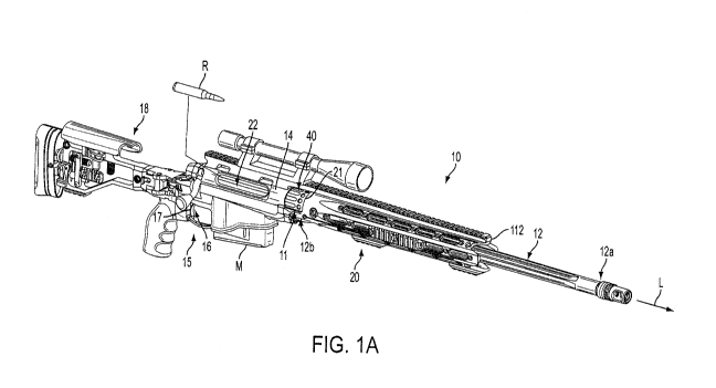
[0008] Fig. IA is an isometric view of a firearm with a quick-detach
barrel mounting
system according to a first exemplary embodiment of the disclosure.
[0009] Fig. 1B is an isometric view of the hand guard and quick-detach
barrel
mounting system of Fig. IA viewed from below the hand guard.
[0010] Fig. 1C is a top view of a portion of the firearm of Figs. 1A-1B.
[0011] Fig. 2 is an exploded isometric view of the barrel, a barrel
extension, a barrel
nut, a bolt assembly, and receiver of the firearm of Fig. 1A.
[0012] Fig. 3 is isometric view of the barrel extension and a bolt head
of the bolt
assembly of Fig. 2.
[0013] Fig. 4 is a cross-sectional view of the barrel mounting and
retention device of
Figs. 1A-1B.
[0014] Figs. 5A-5B are isometric views of the firearm of Fig. IA
illustrating the
detachment and barrel removal according to the principles of the present
invention.
3
CA 02889273 2015-04-22
WO 2014/066759
PCT/US2013/066809
[0015] Fig. 6 is an isometric view of the firearm of Fig. 1A with the
barrel removed
and a tool according to the principles of the present invention.
[0016] Fig. 7 is an isometric view of a firearm with a quick-detach
barrel mounting
system according to a second exemplary embodiment of the disclosure.
[0017] Fig. 8 is an exploded isometric view of features of the firearm of
Fig. 7.
[0018] Fig. 9 is a cross-sectional view of the quick-detach barrel
mounting system of
Fig. 7.
[0019] Fig. 10 is an isometric view of the quick-detach barrel mounting
system of
Fig. 7 with a tool according to the principles of the present invention.
[0020] Those skilled in the art will appreciate and understand that,
according to
common practice, the various features of the drawings discussed below are not
necessarily drawn to scale, and that dimensions of various features and
elements of
the drawings may be expanded or reduced to more clearly illustrate the
embodiments
of the present invention described herein.
DETAILED DESCRIPTION OF THE EXEMPLARY EMBODIMENTS
[0021] Referring now to the drawings in which like numerals indicate like
parts
throughout the several views, the figures illustrate example embodiments of
the
quick-detach barrel mounting and retention apparatus or system according to
the
principles of the present disclosure for use in a firearm such as a precision
sniper rifle
(PSR), modular sniper rifle (MSR), and/or similar types of firearms. However,
it will
be understood that the principles of the barrel mounting and retention device
of the
present invention can be used in various types of firearms including shotguns,
rifles,
and other long guns. The illustrated embodiment, included by way of example,
shows
a bolt action firearm. However, the present disclosure should not be limited
to the
illustrated example. The following description is provided as an enabling
teaching of
exemplary embodiments, and those skilled in the relevant art will recognize
that many
changes can be made to the embodiments described. It also will be apparent
that
some of the desired benefits of the embodiments described can be obtained by
4
CA 02889273 2015-04-22
WO 2014/066759
PCT/US2013/066809
selecting some of the features of the embodiments without utilizing other
features.
Accordingly, those skilled in the art will recognize that many modifications
and
adaptations to the embodiments described are possible and may even be
desirable in
certain circumstances, and are a part of the invention. Thus, the following
description
is provided as illustrative of the principles of the embodiments and not in
limitation
thereof, since the scope of the invention is defined by the claims.
[0022] Fig. IA illustrates a firearm 10 showing a quick-detach barrel
mounting
system 11 in one exemplary embodiment. The firearm 10 generally is shown as a
rifle and includes a barrel 12 extending along a longitudinal axis L and
having a
forward or muzzle end 12a and a proximal or rear end 12b, with the a quick-
detach
barrel mounting system 11 connecting the barrel to an receiver 14. The firearm
further generally includes a chassis 15, and a stock 18. A hand guard 20 also
can be
affixed to at least the receiver 14, extending along the barrel with the
barrel "floating"
therein. For example, the firearm can include a hand guard that is affixed to
the
receiver 14 and/or the chassis 15 by fasteners, for example, or an AR-style
two-piece
receiver and hand guard. Alternatively, the hand guard 20 or any other type of
hand
guard can be integral with and/or otherwise utilized with the firearm 10, or a
hand
guard can be omitted from the firearm. The firearm additionally can
incorporate a
monolithic, integral upper-style receiver and hand guard, wherein the hand
guard is
integrally formed with the receiver. As shown in Figs. 1A-1C, the hand guard
20
generally will include a cutout 21 to provide access to a barrel mounting and
retention
device 40, the cutout 21 and the barrel mounting and retention device 40
forming the
quick-detach barrel mounting system 11. The stock 18, also known as the
buttstock
or shoulder stock, may be formed in any conventional manner to include
cushioning,
special curvatures, grips, hinges, adjustment features, etc.
[0023] The receiver 14 houses and includes the firing mechanism or fire
control 16 of
the firearm, including a trigger 17 for actuating the firearm (Fig. 1A). A
breech bolt
or bolt assembly 22 and a firing pin 24 also generally will be included in the
receiver
14 (Figs. 2 and 4). The bolt assembly 22 is translatable axially in both
forward and
rearward directions along the receiver during the ejection and loading cycle
and
generally is located behind and communicates with a barrel extension 26 and a
CA 02889273 2015-04-22
WO 2014/066759
PCT/US2013/066809
chamber portion 19 (Fig. 4) at the rear end 12b of the barrel 12. The chamber
receives a round of ammunition R (Fig. 1A), such as a shell or cartridge for
firing,
typically from a magazine M (Fig. 1A) received within the chassis 15.
[0024] In the illustrated embodiment, the receiver 14 and the chassis 15
can be
secured together (e.g., with fasteners). As shown in Figs. 2 and 4, the
receiver 14
includes a front end 73 that defines an axial bore 72. The axial bore 72 can
receive a
portion of the barrel extension 26, which is part of the barrel mounting and
retention
device 40 (Fig. 4). The front end 73 includes an externally-threaded portion
73a that
interfaces with a barrel nut 42 of the barrel mounting and retention device 40
(Fig. 4).
As shown in Fig. 2, the front end 73 can include a notch or recess 77 in the
forward
facing surface 75 of the receiver 14 that can receive an alignment feature in
the barrel
extension 26 (Fig. 4).
[00251 As shown in Figs. 1-1C, the hand guard 20 generally will enclose
at least a
portion of the barrel 12 with the barrel affixed to the receiver 14 by the
barrel
mounting and retention device 40 and generally floating or otherwise remaining
free
from connection to the hand guard 20. The hand guard 20 can include one or
more
Picatinny rails 23 and/or other accessory features, and one or more
accessories (e.g., a
scope, a flashlight, etc.) can be affixed to one or more of the Picatinny
rails 23. A
proximal end 25 of the hand guard 20 further can be in abutting contact with
or
otherwise engage a forward face of the chassis 15 (Fig. 1B), and can be
secured
thereto such as by fasteners 27 (e.g., cap screws, rivets, pins, etc.). For
example, in
one embodiment, the fasteners 27 comprise two cap screws that pass through
respective holes in the proximal end 25 and engage respective threaded bores
in the
forward face of the chassis 15 (Fig. 1B). The hand guard 20 also can include
an upper
extension 29 that extends over and is secured to the receiver 14 (Fig. 1C),
such as by
fasteners 31 (e.g., cap screws, rivets, pins, etc.), shown in one embodiment
as
comprising four screws that pass through holes in the upper extension 29 and
engage
respective threaded bores in the top of the receiver 14 (Fig. 1C). In one
embodiment,
the upper extension 29 can include a portion of a monolithic rail that is
integrally
formed with or can be affixed to the receiver and a guard portion of the hand
guard
6
CA 02889273 2015-04-22
WO 2014/066759
PCT/US2013/066809
20. Alternatively, the hand guard 20 can be otherwise secured to or integral
with the
receiver 14 and/or the chassis 15.
[0026] In the illustrated embodiment, the cutout 21 of the hand guard 20
is formed
between a rearward face of the hand guard 20 and the receiver 14 above the
proximal
end 25 of the hand guard (Figs. 1B and 1C). As shown in Fig. IC, the upper
extension 29 of the hand guard 20 can extend over the cutout 21, with the
cutout
including/defining a series of spaced access openings or areas about the
circumference of the hand guard. In one embodiment, the cutout 21 can be
formed
with the hand guard 20 (e.g., the cutout 21 can be formed by a feature of a
mold when
molding the hand guard). Alternatively, or in addition, the cutout 21 can be
cut,
carved, shaved, and/or otherwise formed in the pre-formed hand guard 20. The
cutout
21 can include a first longitudinal edge 33 on a first side 114 of the firearm
10, a
second longitudinal edge 35 on the opposing second side 116 of the firearm,
and a
rearward-facing edge 36 extending between the first longitudinal edge 33 and
the
second longitudinal edge 35. Accordingly, the cutout 21 generally will be
configured
to provide easy access to the barrel nut 42 on either side of the firearm 10
to enable
engagement and manipulation of the barrel nut by hand, from either side of the
firearm, while the hand guard 20 remains attached to the receiver 14 and the
chassis
15. In one embodiment, the cutout 21 is sized so that a tool (e.g., the tool
100 shown
in Fig. 5A) and/or a user's fingers can access and manipulate the barrel nut
42 through
the cutout 21 without removing the hand guard 20, and without diminishing the
stability of the mounting of the barrel or the hand guard to the receiver.
[0027] In the illustrated embodiment, the longitudinal edges 33, 35 of
the cutout are
generally parallel to and disposed below the longitudinal axis L of the barrel
12 so
that the top half and at least a portion of the lower half of the barrel nut
12 are
accessible through the cutout, above the longitudinal edges 33, 35.
Accordingly, a
user can grasp the barrel nut through the cutout 21 below a ridge 110 on one
side of
the firearm and above a generally opposing ridge 110 on the other side of the
firearm
with respective fingers of one or both hands to rotate the barrel nut on the
front end 73
of the receiver 14. The rearward-facing edge 36 of the cutout is spaced apart
from the
front end 73 of the receiver 14 (Fig. 5B), e.g., by a distance approximately
equal to
7
CA 02889273 2015-04-22
WO 2014/066759
PCT/US2013/066809
half the length of the barrel nut, so as to facilitate and ensure a stable
mounting to and
support of the hand guard from the receiver, and to ensure the barrel nut 42
is easily
accessible through the cutout 21 even when the barrel nut is disengaged from
the front
end 73 of the receiver. Accordingly, a user can reach into the cutout 21,
grasp the
barrel nut 42, engage the barrel nut with the front end, and turn the barrel
nut so that
the threaded portion 92 of the barrel nut engages the external threads 73a of
the front
end.
[0028] The cutout 21 and the hand guard 20 also can be otherwise
configured without
departing from the scope of the disclosure. For example, the cutout could be
formed
on a single side of the firearm, or could additionally provide access to the
barrel nut
42 from the top and/or the bottom of the firearm. Still further, the cutout
generally
will be located along the hand guard and will be configured and sized to
accommodate easy and consistent access to the barrel nut by different users
with
various hand sizes, including when users wear gloves, without interfering with
or
otherwise diminishing the strength of the connection between the receiver and
the
hand guard, including integrally formed receivers and hand guards. For
example, the
cutout 21 can provide a total access opening size of approximately 1-4 square
inches,
although greater or lesser total opening sizes also can be used, on one or
both sides of
the firearm 10 to provide clearance for various hand sizes, with a range of
finger sizes
from small fingers to large, gloved fingers to reach through the cutout and
engage the
ridges 110 of the barrel nut and to move up and/or down in the cutout to turn
the
barrel nut.
[0029] In the firearm 10, the bolt assembly 22 is shown in one embodiment
as
including a bolt body 28, a bolt head 30, and a bolt plug 32 (Figs. 2 and 4)
for
operation of the firearm for ejecting a spent shell or casing and reloading
the chamber
after firing by way of translating the bolt assembly 22 of the firearm 10
rearwardly
and forwardly in relation to the receiver 14. During an ejection and loading
operation,
the bolt assembly is rotated and pulled rearwardly away from the chamber
portion 19
of the barrel 12. This rearward translation of the bolt causes a spent
cartridge/shell
casing to be automatically cleared or ejected from the chamber 19 (e.g., by an
extractor and ejector mechanism in the bolt head 30). A new round R then can
be
8
CA 02889273 2015-04-22
WO 2014/066759
PCT/US2013/066809
advanced and positioned adjacent the bolt head 30 by the magazine M, and the
bolt
assembly 22 can be pushed forward and locked into engagement with the barrel
extension 26 so that the round R is loaded into the chamber. The bolt can be
recocked
and readied for firing.
[0030] As shown in Figs. 2-4, the barrel mounting and retention device 40
includes a
barrel nut 42 and the barrel extension 26, which cooperate to secure and
retain the
barrel 12 in abutting engagement with the receiver 14. As shown in Figs. 2-4,
the
barrel extension 26 generally includes a cylinder section 46 and an annular
boss or
collar 48. The cylinder section 46 can include an axial bore 50 extending from
a bolt-
receiving end 52 of the barrel extension 26 to a barrel-receiving end 54
adjacent the
collar 48. As shown in Figs. 3 and 4, the axial bore 50 can include a bolt-
interlocking
section 56 adjacent the bolt-receiving end 52 and a threaded section 58
extending
from the bolt interlocking section 56 to the barrel-receiving end 54 for
engaging
external threads 59 formed about the rear end 12b or the chamber portion 19 of
the
barrel 12 (Figs. 2 and 4). The cylinder section 46 can slide axially into the
axial bore
72 of the receiver 14 (Figs. 2 and 4) to interface with the bolt assembly 22
of the
firearm 10.
[0031] As shown in Figs. 3 and 4, the bolt-receiving end 52 further
includes a
plurality of locking lugs 60 extending radially into the axial bore 50 with
recesses 62
formed between the locking lugs 60. The bolt head 30 of the bolt assembly 22
can
include a plurality of corresponding lugs 61 and recesses 63 at its forward
end. The
lugs 61 of the bolt head 30 can engage the recesses 62 of the barrel extension
26 and
the locking lugs 60 of the barrel extension 26 can engage the recesses 63 of
the bolt
head 30 when the forward end of the bolt head 30 is passed through the bolt-
receiving
end 52 and into the interlocking section 56 of the barrel extension 26, such
as when
chambering a round R into the chamber 19. Thereafter, with the lugs 61 of the
bolt
head 30 received within the interlocking section 56 (Fig.4), the bolt assembly
22 can
be rotated to at least partially align the lugs 61 of the bolt head 30 with
the locking
lugs 60 to lock the bolt assembly 22 to the barrel extension 26 (Fig. 4) for
firing the
firearm 10. After a firing operation, the bolt assembly can be rotated in an
opposite
direction so that the lugs 61 of the bolt head 30 are generally aligned with
the recesses
9
CA 02889273 2015-04-22
WO 2014/066759
PCT/US2013/066809
62 of the barrel extension 26 and the bolt head 30 then can be pulled
rearvvardly to
withdraw from the barrel extension 26 (Fig. 3) to extract a spent shell or
cartridge
casing from the chamber prior to chambering another round. The bolt assembly
22
can include a bolt handle 34 extending from the bolt body 28. The bolt handle
34 can
be grasped for rotating and translating the bolt assembly 22 within the
receiver 14.
Alternatively, the bolt assembly 22 and the ejection and loading cycle can be
controlled by a gas operating system in an automatic or semi-automatic
firearm.
[0032] As shown in Fig. 4, the threaded section 58 of the axial bore 50
can receive the
rear end 12b of the barrel 12, which includes at least a portion of the
chamber 19. The
threaded section 58 can be threaded for interfacing with the external threads
59
formed about the rear end 12b of the barrel 12 for attaching the barrel to the
barrel
extension. The collar 48 can engage and abut against a shoulder 66 proximate
the
external threads 59 of the barrel 12 when the barrel extension 26 is in
engagement
with the rear end 12b of the barrel. Alternatively, an annular barrel stop
shoulder can
be formed within the axial bore at the barrel-receiving end 54, and the barrel
stop
shoulder can engage the rearward face of the shoulder 66.
[0033] As shown in Figs. 2-4, the collar 48 of the barrel extension 26
generally
includes a rearward face 68 and a forward face 70. The rearward face 68
extends
outwardly from the cylinder section 46 in a generally radial direction to
provide a
generally flat rearward facing surface for engaging the forward facing surface
75 of
the receiver 14 (Figs. 2 and 4). Accordingly, a clamp force applied along the
longitudinal axis L of the barrel 12 tends to urge the rearward face 68
against the
forward surface 75 of the receiver. The generally flat nature of the rearward
face 68
allows proper seating of the collar 48 against the receiver 14 for secure
retention of
the barrel extension 26, and thus the barrel 12, to the receiver 14, as well
as proper
alignment of the longitudinal axis L of the barrel 12 with a longitudinal axis
of the
receiver, with minimal effort by a user. No tools are required for alignment
of the
barrel and the receiver.
[0034] In the illustrated embodiment, the barrel extension 26 can be
inserted into the
axial bore 72 of the front end 73 of the receiver 14 until a rearward face 74
of the
CA 02889273 2015-04-22
WO 2014/066759
PCT/US2013/066809
bolt-receiving end 52 of the barrel extension 26 engages a stop shoulder 76 of
the
axial bore 72 of the receiver. The axial bore 72 and the cylinder section 46
can be
configured so that both of the rearward faces 68, 74 of the barrel extension
26 engage
the respective forward surface 75 and stop shoulder 76 of the receiver 14, or
only one
of the rearward faces 68, 74 engages the respective forward surface 75 or stop
shoulder 76. While the rearward faces 68, 74, the forward surface 75, and the
stop
shoulder 76 are generally perpendicular to the longitudinal axis L of the
firearm as
shown in the figures, one or more of these features can be oblique and/or
curved to
encourage alignment and/or proper seating of the respective features.
[0035] As shown in Figs. 2-4, the barrel extension 26 can include an
alignment pin 78
extending radially from the cylinder section 46 that engages the recess 77 in
the
forward surface 75 of the receiver 14 (Figs. 2 and 4). In the illustrated
embodiment,
the alignment pin 78 is seated in a bore in the cylinder section 46 of the
barrel
extension 26 and is secured by adhesive or an interference fit with the bore,
for
example. Alternatively the alignment pin 78 can be integral with the cylinder
section
46 and/or the collar 48. The alignment pin 78 and the recess 77 can be
configured so
that when the alignment pin 78 engages the recess 77 (Fig. 4), the bolt
interlocking
section 56 of the barrel extension 26 is properly aligned within the receiver
to receive
the forward portion of the bolt head 30 and to interlock with the bolt head
30. The
barrel extension 26 could be otherwise configured or omitted without departing
from
the disclosure. For example, the collar 48, the locking lugs 60 and recesses
62, and/or
the alignment pin 78 could be formed with (e.g., integral with) and/or
directly
attached to the rear end 12b of the barrel 12.
[0036] As illustrated in Figs. 2 and 4, the barrel nut 42 can include a
body 80 defining
an axial bore 82 and a plurality of radial bores 84. The axial bore 82 can
provide
clearance for the rear end 12b and the shoulder 66 of the barrel 12 to pass
through and
engage the barrel extension 26. Accordingly, the barrel nut 42 can slide over
and
along the barrel 12 to engage the collar 48 of the barrel extension 26 and the
front end
73 of the receiver 14, as shown in Figs. IA and 4. In the illustrated
embodiment, the
barrel nut 42 includes a forward end 86, a rearward end 88, an intermediate
annular
11
CA 02889273 2015-04-22
WO 2014/066759
PCT/US2013/066809
shoulder 90, and a threaded portion 92 extending from the rearward end 88 to
proximate the intermediate annular shoulder 90.
[0037] As shown in Figs. 1A-2, 5A, and 6, the radial bores 84 are
disposed between
the forward end 86 and the intermediate annular shoulder 90 and generally are
spaced
substantially equally around a circumference of the body 80 of the barrel nut
42. The
number of radial bores 84 can be varied with there being a sufficient number
and
spacing between the bores to enable engagement thereof from either side and
from
various angles as needed for disengagement of the barrel nut. The radial bore
can be
any suitable mating geometry (e.g., various bore shapes, slits, cutouts,
protuberances,
detents, grooves, etc.) without departing from the disclosure. The threaded
portion 92
is configured to provide clearance for the collar 48 and is internally
threaded to
engage the externally-threaded portion 73a of the front end 73 of the receiver
14
(Figs. 2 and 4). Accordingly, the barrel nut 42 can be tightened onto the
front end 73
over the barrel 12 and the barrel extension 26 until the intermediate annular
shoulder
90 engages the forward face 70 of the collar 48, thereby securing the barrel
12 and the
barrel extension 26 in the front end 73 of the receiver 14. In one embodiment,
the
barrel nut 42 and the front end 73 can apply a clamp force to the collar 48
between the
forward facing surface 75 of the receiver 14 and the intermediate annular
shoulder 90
of the barrel nut 42.
[0038] In the illustrated embodiment, the radial bores 84 of the barrel
nut 42 can be
configured to receive an end of a tool 100, which can include a variety of
wrenches,
pry-bars, or other similar tools, including knives and other common tools used
by
soldiers and hunters in the field that can be used to engage at least one
radial bore 84
for tightening and at least initially loosening the barrel nut 42 from its
engagement
with the front end 73 of the receiver 14. By way of example, as shown in Fig.
5A, the
tool 100 can include an elongate handle 102, one or more tool projections 104,
and a
tool guard 106. The tool projection 104 can be received in any of the radial
bores 84
of the barrel nut 42 that is accessible through the cutout 21 in the hand
guard 20 (Figs.
1A-1C). The tool guard 106 can have a curved surface for engaging the curved
outer
surface of the barrel nut 42. The tool 100 is shown by way of example only.
Generally, any suitable tool can be used to interface with the radial bores 84
(or other
12
CA 02889273 2015-04-22
WO 2014/066759
PCT/US2013/066809
mating geometries) of the barrel nut 42 to provide a mechanical advantage for
tightening and loosening the barrel nut 42 of the front end 73 of the receiver
14. For
example, the tool can be a torque wrench, and/or it can include multiple
prongs,
projections, recesses, etc. for engaging multiple radial bores 84 or other
mating
geometries. The tool also can be compact for easier carrying and storing, for
example, including a shortened or a telescoping and/or folding handle/tool
body for
compact storage and providing more mechanical advantage in use.
100391 The barrel nut 42 further can include ridges 110 to provide a
gripping surface
that can be used for tightening and loosening the barrel nut 42 on the front
end 73 of
the receiver 14. Accordingly, the barrel nut 42 can be initially tightened
onto the
front end 73 by a user's fingers, which can grip the ridges 110 and rotate the
barrel
nut 42 in the clockwise direction. The barrel nut 42 can be securely tightened
onto
the front end 73 by inserting the tool projection 104 into an radial bore 84
at the
cutout 21 and pushing or pulling the handle 102 of the tool 100 to rotate the
barrel nut
42 in the clockwise direction. Similarly, the barrel nut 42 can be initially
loosened by
inserting the tool projection 104 into an radial bore 84 at the cutout 21 and
pushing or
pulling the handle 102 to rotate the barrel nut 42 in the counterclockwise
direction. A
user then can loosen the barrel nut 42 further by gripping the barrel nut 42
at the
ridges 110 and rotating the barrel nut 42 in the counterclockwise direction.
100401 As shown in Fig. 5A, the tool 100 can access the barrel nut 42
through the
cutout 21 on the first side 114 of the firearm 10 so that pushing up on the
tool 100
rotates the barrel nut 42 in a clockwise motion to tighten the barrel nut 42
onto the
front end 73 of the receiver 14. Pulling down on the tool 100 on the first
side 114 of
the firearm 10 rotates the barrel nut 42 in a counterclockwise motion to
loosen the
barrel nut 42. Alternatively, the tool 100 can access the barrel nut 42
through the
cutout 21 on the opposing second side 116 of the firearm 10 so that pulling
down on
the tool 100 rotates the barrel nut 42 in a clockwise motion to tighten the
barrel nut 42
onto the front end 73 and pushing up on the tool 100 rotates the barrel nut 42
in a
counterclockwise motion to loosen the barrel nut 42. In an alternative
embodiment,
the threaded portion 92 of the barrel nut 42 and the externally-threaded
portion 73a of
the front end 73 could be threaded so that turning the barrel nut 42 in a
13
CA 02889273 2015-04-22
WO 2014/066759
PCT/US2013/066809
counterclockwise motion tightens the barrel nut 42 onto the front end 73 and
rotating
the barrel nut 42 in a clockwise motion loosens the barrel nut 42.
[0041] According to one embodiment, the barrel 12 of the firearm 10 can
be
exchanged with an another barrel 12 without disassembling the hand guard
assembly
20 and/or other features of the firearm. For example, the barrel may be
replaced by a
barrel with a different length and/or that is configured for use with a
different caliber
of ammunition. The original barrel extension 26 and barrel nut 42 can be used
with
the alternate barrel, or one or both of the barrel extension 26 and barrel nut
42 can be
replaced with the barrel. In the illustrated embodiment, the barrel change-out
operation can be initiated by disengaging the bolt assembly 22 from the barrel
extension 26 and retracted within the receiver 14. For example, the bolt
handle 34
can be manipulated to rotated the bolt assembly 22 and align the lugs 61 of
the bolt
head 30 with the recesses 62 of the barrel extension 26. The bolt assembly 22
can
then be at least partially retracted in the receiver 14 so that the lugs 61
pass through
the recesses 62 and the bolt head 30 is removed from the bolt-receiving end 52
of the
barrel extension 26. The bolt assembly 22 can be fully removed from the
receiver 14
so that the firing pin 24, the bolt head 30, and/or other features of the bolt
assembly
22 can be replaced.
[0042] As shown in Fig. 5A, the tool projection 104 of the tool 100 can
be inserted
into one of the radial bores 84 that is accessible through the cutout 21 of
the hand
guard assembly 21. In Fig. 5A, the tool 100 is inserted through the cutout 21
from the
first side 114 of the firearm 10; however, the tool 100 could be inserted
through the
cutout 21 from the second side 116 of the firearm. With the tool projection
104
inserted into the respective radial bore 84, the tool guard 106 of the tool
100 can
contact the outer surface of the barrel nut 42 adjacent the radial bore 84.
Pulling
downwardly on the handle 102 of the tool 100 can help loosen the barrel nut 42
on the
front end 73 of the receiver 14. Friction due to contact between the
intermediate
annular shoulder 90 of the axial bore 82 of the barrel nut 42 and the forward
face 70
of the collar 48 of the barrel extension 26 can resist rotation of the barrel
nut 24
relative to the barrel extension 26 and the front end 73. Additionally,
residue can
build up between the annular should 90 of the barrel nut 42 and the collar 48
of the
14
CA 02889273 2015-04-22
WO 2014/066759
PCT/US2013/066809
barrel extension 26 and/or between the threaded portions 73a, 92 from the
primer and
the propellant of the rounds R after several firing operations to form an
adhesive bond
between the barrel nut 42 and the front end 73. Also, stress from firing
operations can
further tighten the barrel nut 42 on the front end 73, which can make it more
difficult
to initiate turning of the barrel nut 42. However, the tool 100 can form a
lever to
provide a mechanical advantage to overcome the friction and any adhesion
between
the annular shoulder 90 and the collar 48 and/or the threaded portions 73a, 92
and to
rotate the barrel nut 42 in a counterclockwise motion.
[0043] The interfacing of the threaded portion 92 of the barrel nut 42
and the
externally-threaded portion 73a of the front end 73 moves the barrel nut 42
away from
the receiver 14 and the barrel extension 26 along the longitudinal axis L as
the barrel
nut 42 rotates in the counterclockwise direction. Accordingly, the
intermediate
annular shoulder 90 of the barrel nut 42 is moved away from the forward face
70 of
the collar 48 so that the barrel nut 42 can be more easily rotated in the
counterclockwise direction. The tool 100 can be withdrawn from the firearm 10,
and
the barrel nut 42 can be further rotated in the counterclockwise direction
with a user's
fingers until the threaded portion 92 of the barrel nut 42 is disengaged from
the
externally-threaded portion 73a of the front end 73 (Fig. 5B).
[0044] In the illustrated embodiment, after the bolt head 30 has been
disengaged from
the bolt-interlocking section 56 of the barrel extension 26 and the barrel nut
42 has
been disengaged from the front end 73 of the receiver 14 (Fig. 5B), the barrel
12 can
be pulled away from the receiver 14, withdrawing the cylinder section 46 from
the
axial bore 72 of the receiver 14. As shown in Fig. 6, the barrel 12, the
barrel
extension 26, and the barrel nut 42 can be pulled through a forward end 112 of
the
hand guard 20 to be fully removed from the firearm 10 while the hand guard 20
remains mounted on the receiver 14 and/or the chassis 15. The barrel 12, the
barrel
extension 26, and the barrel nut 42 can be removed from the firearm 10 by
other steps
and/or features without departing from the disclosure.
[0045] In one embodiment, the barrel 12, the barrel extension 26, and the
barrel nut
42 can be reassembled to the receiver 14 by generally reversing the removal
steps.
CA 02889273 2015-04-22
WO 2014/066759
PCT/US2013/066809
Particularly, the rear end 12b of the barrel 12 can be engaged with the axial
bore 50 of
the barrel extension 26 by screwing the threaded portion 59 of the rear end
12b into
the threaded section 58 of the axial bore 50 until the forward face 70 of the
barrel
extension 26 engages the shoulder 66 of the barrel 12. In a particular
embodiment,
the rear end 12b can be further secured to the barrel extension 42 with
adhesives, set
screws, other fasteners, or combinations thereof, although such additional
attachment
devices are not required with the present disclosure. The barrel nut 42 can
slide over
the barrel 12 from the muzzle end until the axial bore 82 of the barrel nut 42
is
proximate the rear end 12b of the barrel (Fig. 6). The barrel extension 26,
the barrel
12, and the barrel nut 42 can be inserted through the forward end 112 of the
hand
guard 20 and the cylinder section 46 of the barrel extension 26 can be
inserted into the
axial bore 72 of the receiver 14. The barrel 12 and the barrel extension 26
can be
rotated to align the alignment pin 78 of the barrel extension 26 with the
recess 77 of
the front end 73 of the receiver 14, and the barrel extension 26 can be
further inserted
into the axial bore 72 until the alignment pin 78 is received in the recess 77
(Fig. 4)
and the rearward face 68 of the collar 48 of the barrel extension 26 engages
the
forward facing surface 75 of the receiver 14 and/or the rearward face of the
bolt-
receiving end 52 of the barrel extension 26 engages the stop shoulder 76 of
the
receiver 14 (Fig. 4).
100461 The barrel nut 42 can be secured onto the front end 73 of the
receiver 14 by
engaging the threaded portion 90 of the barrel nut 42 with the externally-
threaded
portion 73a of the front end 73 and rotating the barrel nut 42 in the
clockwise
direction. A user can initially tighten the barrel nut 42 on the front end 73
with
fingers by gripping the ridges 110 through the cutout 21 of the hand guard
assembly
20 on one or both sides 114, 116 of the firearm 10 and rotating the barrel nut
42 at
least until the radial bores 84 are disposed within the cutout 21. With the
radial bores
84 accessible through the cutout 21, the tool projection 104 of the tool 100
can be
inserted into one of the radial bores 84 (e.g., from the first side 114 of the
firearm 10
as shown in Fig. 5A). The handle 102 of the tool 100 can be pushed upwardly in
order to tighten barrel nut 42 onto front end 73 until the intermediate
annular shoulder
90 of the barrel nut 42 engages forward face 70 of the collar 48 of the barrel
extension
16
CA 02889273 2015-04-22
WO 2014/066759
PCT/US2013/066809
26 (Fig. 4). Accordingly, the barrel nut 42 can clamp the collar 48 between
the
forward facing surface 75 of the receiver 14 and the intermediate annular
shoulder 90
of the barrel nut 42 to help secure the barrel 12 and the barrel extension 26
to the
receiver 14. The bolt assembly 22 can be pushed forward within the receiver 14
so
that the bolt head 30 engages the bolt-interlocking section 56 of the barrel
extension
26. Accordingly, the lugs 61 of the bolt head 30 can be aligned with the
recesses 62
between the locking lugs 60 of the barrel extension 26, bolt assembly 22 can
be
pushed forward so that the lugs 61 are generally clear of the locking lugs 60
within
the axial bore 50 of the barrel extension 26. The bolt assembly 22 can be
rotated by
the bolt handle 34 so the lugs 61 are aligned with the locking lugs 60 and the
bolt
head 30 is locked with the barrel extension 26 (Fig. 4). The barrel 12, the
barrel
extension 26, and the barrel nut 42 can be secured to the firearm 10 by other
steps
and/or features without departing from the disclosure.
[0047] In one embodiment, the firearm 10 can be prepared for firing by
engaging the
magazine M with rounds R with the chassis 15, rotating the bolt assembly 22 by
the
bolt handle 34 to align the lugs 61 with the recesses 62, and pulling the bolt
assembly
22 rearwardly in the receiver 14 by the handle 34 so that a round R can enter
the
receiver 14 ahead of the forward-facing end of the bolt head 30. The bolt
assembly
22 can be pushed forwardly in the receiver 14 by the handle 34 to push the
round R
forwardly toward the chamber 19. The bolt assembly 22 can be locked with the
barrel
extension 26 as described above, while the bolt head 30 pushes the round R
into the
chamber 19. The firing operation can be actuated by operating the fire control
16
(e.g., pulling the trigger 17). After the firing operation, the bolt assembly
22 can be
withdrawn in the receiver 14 to eject the spent cartridge or shell casing of
the round R
and to receive a new round R for chambering and preparing for firing.
[0048] In operation, the firearm 10 (Fig. 1) is prepared for firing when
the bolt
assembly 22 loads a round of ammunition R in to the chamber portion 19 of the
firearm. The bolt head 30 carries the round R into the axial bore 50 at the
bolt-
receiving end 52 of the barrel extension 26 and the lugs 61 of the bolt head
30 pass
through the recesses 62 between the locking lugs 60 at the bolt-receiving end
52.
With the lugs 61 in the interlocking section 56, the round R is fully inserted
into the
17
CA 02889273 2015-04-22
WO 2014/066759
PCT/US2013/066809
chamber portion 19 of the barrel 12, and the bolt assembly 22 is rotated to
align the
lugs 61 with the locking lugs 60 at the bolt-receiving end 52 and lock bolt
assembly
22 to the barrel extension 42 with the round R in the chamber portion 19. When
the
fire control 16 is actuated, the firing pin 24 strikes the primer of the
round, igniting
the propellant. Expanding gases from the ignited propellant build up pressure
in the
barrel 12, driving the bullet portion of the round through the down bore
section 12a of
the barrel. The bolt assembly 22 then can be rotated to unlock the lugs 61
from the
barrel extension 42 and to extract the spent casing of the round R from the
chamber
19. The spent casing can be ejected from the firearm 10 and a new round can be
loaded into the chamber.
100491 Fig. 7 is a perspective view of a quick-detach barrel mounting
system 211 for
a firearm according to a second embodiment of the disclosure. The second
embodiment generally is similar to the first embodiment, except for various
additional
noted features and variations that will be apparent to one of ordinary skill
in the art.
Accordingly, similar or identical features of the embodiments have been given
like or
similar reference numbers. As shown in Fig. 7, the quick-detach barrel
mounting
system 211 is associated with a firearm 210, which can be similar to the
firearm 10 of
the first embodiment shown in Fig. 1. The firearm 210 can include a barrel 212
mounted to a receiver 214, which is mounted to a chassis 215. The hand guard
assembly 220 can be similar or identical to the hand guard assembly 20 of the
first
embodiment and can include the cutout 21. The hand guard assembly 220 can be
mounted to the chassis 215 and the receiver 214 with the barrel 212 extending
(e.g.,
"floating") therein in a similar or identical manner that the hand guard
assembly 20 is
mounted to the chassis 15 and the receiver 14.
[0050] As shown in Fig. 7, the barrel 212 includes a forward or muzzle
end 212a and
a proximal or rear end 212b. As shown in Figs. 8 and 9, the proximal end 212b
can
include external threads 259 for threadably engaging internal threads 273a of
an axial
bore 272 in the receiver 214. In one embodiment, turning the barrel 212 in a
clockwise direction (as viewed from the muzzle end 212a) can move the barrel
rearwardly into the axial bore 272 of the receiver, and turning the barrel in
a
counterclockwise direction can move the barrel forwardly, out of the receiver
214. A
18
CA 02889273 2015-04-22
WO 2014/066759
PCT/US2013/066809
bolt assembly 222 can be at least partially disposed in the receiver 214 and
can
translate axially along the receiver during the ejection and loading cycle of
the
firearm. The bolt assembly 222 is located behind and communicates with a
chamber
portion 219 at the proximal end 212b of the barrel 212 in the axial bore 272
of the
receiver 214 (Fig. 9). The chamber 219 receives a round of ammunition (Fig.
7), such
as a shell or cartridge for firing.
[0051] In the illustrated embodiment, a recoil lug or barrel bracket 294
(Figs. 8 and 9)
can be disposed on the proximal end 212b of the barrel 212 adjacent the
forward
facing surface 275 of the receiver 214. The barrel bracket 294 can include a
barrel-
receiving bore 295 and a flange 296. The proximal end 212b of the barrel can
extend
through the barrel-receiving bore 295, and the flange 296 can be received in a
slot 297
in the chassis 215 (Figs. 8 and 9). An alignment pin 298 can be received in a
corresponding alignment bore 299 in the barrel bracket 294 and the forward
facing
surface 275 of the receiver in order to help align the barrel bracket 294 with
the
receiver 214. The alignment pin 298 can be secured (e.g., press fit, glued,
etc.) within
the bore in the barrel bracket 294 or the forward facing surface 275 of the
receiver.
The barrel bracket 294 can be otherwise configured or omitted without
departing from
the scope of the disclosure.
[0052] As shown in Figs. 8-10, the quick-detach barrel mounting system
211 includes
a cutout 21 along the hand guard 220 and an barrel nut 242 that can be
configured as a
jam nut. The barrel nut 242 can include a body 280 defining an axial bore 282.
In the
illustrated embodiment, the barrel nut 242 includes a forward end 286, a
rearward end
288, a forward facing, intermediate annular shoulder 290, and a threaded
portion 292
extending from the rearward end 288 to proximate the forward facing shoulder
290.
The axial bore 282 can receive the rear end 212b of the barrel, and the
forward facing
shoulder 290 can be configured to engage a shoulder 266 at the forward end of
the
proximal end 212b of the barrel 212 to help prevent the barrel nut 242 from
sliding
forwardly along the barrel. The threaded portion 292 can engage external
threads 259
of the proximal end 212b so that, for example, turning the barrel nut 242 in
the
clockwise direction (as viewed from the muzzle end 212a) can move the barrel
nut
rearwardly along the proximal portion 212b, and turning the barrel nut in the
19
CA 02889273 2015-04-22
WO 2014/066759
PCT/US2013/066809
counterclockwise direction will move the barrel nut forwardly until the
forward facing
shoulder 290 engages the shoulder 266 of the barrel 212. The barrel nut 242
can be
otherwise configured or omitted without departing from the scope of the
disclosure.
[0053] As shown in Fig. 8, the barrel nut 242 further can include ridges
310 to
provide a gripping surface that can be used for turning the barrel nut 242 on
the
proximal end 212b of the barrel 212. The ridges 310 can define recesses or
grooves
284 between adjacent ridges, and the grooves 284 can be configured for mating
with a
spanner wrench 300 (Fig. 10). The grooves 284 can be any suitable mating
geometry
(e.g., various bore shapes, slits, cutouts, protuberances, detents, etc.)
without
departing from the disclosure. Alternatively, the barrel nut 242 can include
radial
bores 84, cuts or recesses for mating with the tool 100 of the first
embodiment.
[0054] In the illustrated embodiment, the spanner wrench 300 can include
a body 301
with a bracket portion 302 and a semicircular or arc-shaped engaging portion
303.
The bracket portion 302 can include an opening 305, which can be configured to
receive a torque wrench (not shown) or other tool (e.g., a lever).
Alternatively, the
bracket portion 302 can be formed as an elongate handle. As shown in Fig. 8,
arc-
shaped portion 303 includes spaced apart projections 304 that generally can be
spaced
so as to align with the grooves 284 of the barrel nut 242. The indented
portions
between the projections 304 also can provide clearance for the ridges 310. The
spanner wrench 300 can be otherwise configured or omitted without departing
from
the scope of the disclosure. In one alternative embodiment, the spanner wrench
300
could be replaced by any suitable tool for engaging one or more grooves 284
and/or
ridges 310. In another alternative embodiment, the arc-shaped engaging portion
303
of the spanner wrench can be formed as a closed circle, and can include an
elongate,
longitudinal rod (not shown). Such a closed circular engaging portion of the
spanner
wrench can be placed over the muzzle end 212a of the barrel 212, and the rod
can be
used to push the alternative spanner wrench rearwardly along the barrel, and
along the
interior of the hand guard 220, until the bracket portion 302 is accessible
via the
cutout 21 of the hand guard.
CA 02889273 2015-04-22
WO 2014/066759
PCT/US2013/066809
[0055] Accordingly, the barrel nut 242 can be initially tightened against
the barrel
bracket 294 by a user's fingers, which can grip the ridges 310 and rotate the
barrel nut
242 in the clockwise direction. The barrel nut 242 further can be securely
tightened
against the barrel bracket 294 by sliding the spanner wrench 300 over the
barrel nut
242 with the projections 304 sliding along the grooves 284 and then pushing or
pulling the spanner wrench 300 to further rotate the barrel nut 242 in the
clockwise
direction. When the barrel nut 242 is sufficiently tightened on the proximal
end 212b
of the barrel 212, the barrel nut clamps the barrel bracket 294 against the
forward
facing surface 275 of the receiver 214, and the threaded portion 292 of the
barrel nut
pulls the external threads 259, and thus the proximal portion 212b, forwardly.
The
pulling of the proximal portion 212b is resisted by the interaction of the
internal
threads 273a of the axial bore 272 of the receiver and the external threads
259 of the
proximal end. Accordingly, tightening of the barrel nut 242 increases the
friction
between the external threads 259 of the barrel and the internal threads 273a
of the
receiver, which frictional engagement can help resist turning forces, recoil
forces,
vibrations, and other forces that can lead to loosening of the proximal end
212b in the
axial bore 272 of the receiver. To change the barrel, the barrel nut 242
thereafter can
be initially loosened by sliding the spanner wrench 300 over the barrel nut to
engage
the projections 304 with the grooves 284 and then pushing or pulling the
spanner
wrench to rotate the barrel nut 242 in the counterclockwise direction. A user
then can
loosen the barrel nut 242 further by removing the spanner wrench 300, gripping
the
barrel nut 242 at the ridges 310, and rotating the barrel nut 242 in the
counterclockwise direction.
[0056] In one embodiment, the barrel 212 of the firearm 210 can be
exchanged (e.g.,
for a barrel configured for a different caliber of ammunition, for a barrel
with a
different length, and/or to replace a worn-out barrel) with the quick-detach
barrel
mounting system 211. Accordingly, the spanner wrench 300 can be inserted into
the
cutout 21 of the hand guard 220 on either side of the firearm 210 so that the
arc-
shaped portion 303 is disposed over the rearward end 288 of the barrel nut
242, to the
rear of the ridges 310. Alternatively, the arc-shaped engaging portion 303
could be
positioned over the barrel 212 adjacent the forward end 286 of the barrel nut
242.
21
CA 02889273 2015-04-22
WO 2014/066759
PCT/US2013/066809
The projections 304 of the spanner wrench 300 are generally aligned with
respective
grooves 284 of the barrel nut 242, and the spanner wrench is moved along the
barrel
nut 242 so that the projections 304 slide within the grooves 284.
[0057] A tool, such as a torque wrench (e.g., the tool 100 of the first
embodiment), a
lever, etc., also can be engaged with the opening 305 of the spanner wrench
300, and
the tool can be used to push or pull the spanner wrench in the
counterclockwise
direction (as viewed from the muzzle end 212a of the barrel 212). Accordingly,
the
projections 304 of the spanner wrench will push against the sides of the
respective
grooves 284 of the barrel nut to urge the barrel nut 242 in the
counterclockwise
direction to help overcome the forces helping to retain the barrel nut 242 in
position
(e.g., the friction between the rearward end 288 of the barrel nut and the
barrel bracket
294, stresses causing friction between the threaded portion 292 of the barrel
nut and
the external threads 259 of the proximal end 212b of the barrel, residue build-
up
between the barrel nut and the proximal end of the barrel, etc.). As the
barrel nut 242
rotates in the counterclockwise direction, the barrel nut will be moved
forward along
the proximal end 212b of the barrel 212 and away from the receiver 214 and the
barrel
bracket 294.
[0058] After the barrel nut 242 is initially loosened on the proximal end
212b of the
barrel, the spanner wrench 300 can be removed by sliding the spanner wrench
forwardly or rearwardly along the barrel nut until the projections 304 are
disengaged
from the grooves 284. The spanner wrench then can be removed through the
cutout
21, and a user can reach through the cutout 21 and grasp the barrel nut 242 at
the
ridges 310 to continue turning the barrel nut in the counterclockwise
direction so that
the barrel nut moves forwardly on the proximal end 212b. In one embodiment,
the
barrel nut 242 can be rotated until the forward facing shoulder 290 of the
barrel nut
engages the shoulder 266 of the barrel. With the barrel nut 242 moved away
from the
receiver 214, the tension between the external threads 259 of the proximal end
212b
of the barrel 212 and the internal threads 273a of the axial bore 272 of the
receiver
214 will be reduced, and the barrel 212 can be rotated in the counterclockwise
direction to unscrew the proximal end 212b from the axial bore 272.
Accordingly, the
barrel 212 can be withdrawn from the rest of the firearm 210 through the
barrel-
22
CA 02889273 2015-04-22
WO 2014/066759
PCT/US2013/066809
receiving bore 295 of the barrel bracket 294 and the interior of the hand
guard 220.
The barrel nut 242 further can be rotated in the clockwise direction to
unscrew the
barrel nut from the proximal end 212b of the barrel. The barrel 212 can be
removed
by other steps and/or features without departing from the present disclosure.
[0059] To install the new barrel, the barrel nut 242 can be engaged with
the proximal
end 212b of the new/different barrel 212 by inserting the proximal end into
the
forward end 286 of the barrel nut and engaging the threaded portion 292 with
the
external threads 259 of the proximal end of the barrel. The barrel nut 242
then can be
screwed onto the proximal end of the barrel until the forward facing shoulder
290
engages the shoulder 266 of the barrel 212. A gauge 318 can be inserted into
the
chamber 219 of the barrel for helping to position the proximal end 212b in the
axial
bore 272 of the receiver 214 with the proper spacing from the bolt assembly
222 in
the locked, ready to fire position for ensuring proper safe case support and
rifle
function. The gauge 318 can be otherwise configured or omitted without
departing
from the description.
[0060] Thereafter, the proximal end 212b of the barrel and the barrel nut
242 can be
inserted through the forward end of the hand guard 220, and the proximal end
can be
inserted through the barrel-receiving bore 295 of the barrel bracket 294 to
engage the
axial bore 272 of the receiver. The external threads 259 of the proximal end
can be
engaged with the internal threads 273a of the axial bore 272, and the proximal
end
212b can be screwed into the axial bore 272 by rotating the barrel 212 in the
clockwise direction. As shown in Fig. 9, with the bolt assembly 222 in the
locked
position (e.g., moved forward in the receiver 214 and with the bolt head
engaged with
the axial bore 272), the gauge 318 will engage the bolt head and prevent
further
movement of the proximal end 212b into the axial bore 272. Accordingly, the
installation of a gauge 318 can help to position the barrel in the receiver.
[0061] In the illustrated embodiment, a user can reach into the cutout 21
of the hand
guard 220, grasp the barrel nut 242 at the ridges 310, and rotate the barrel
nut 242 in
the clockwise direction to move the barrel nut rearwardly along the external
threads
259 of the proximal portion 212b. The user can initially tighten the barrel
nut 242
23
CA 02889273 2015-04-22
WO 2014/066759 PCT/US2013/066809
against the barrel bracket 294 with fingers, for example. The spanner wrench
300 can
be inserted into the cutout 21 so that the arc-shaped portion is forward or
rearward of
the ridges 310. The projections 304 can be aligned with the grooves 284 and
the
spanner wrench 300 can slide over the barrel nut 242 with the projections 304
engaged with the grooves 284. A tool (e.g., torque wrench) then can be engaged
with
the opening 305 of the spanner wrench 300 to tighten the barrel nut 242 on the
proximal end 212b of the barrel against the receiver 214, clamping the barrel
bracket
294 between the rearward end 288 of the barrel nut and the forward facing
surface
275 of the receiver and tensioning the external threads 259 of the proximal
end 212b
against the internal threads 273a of the axial bore 272.
[0062] It therefore can be seen that the construction of the firearm with
a barrel
mounting and retention device according to the principles of the present
disclosure
provides a firearm with an apparatus for affixing and retaining the barrel in
a locked
engagement with the receiver while further providing for substantially quick
and easy
attachment and removal of the barrel with the receiver without requiring
extensive
disassembly of the firearm. Thus, the barrel mounting and retention device
facilitates
a user's easy-attachment and removal/replacement of the barrel to the receiver
of a
firearm, including firearms with integral or monolithic receivers having hand
guards
integrally attached or formed therewith. The present barrel mounting and
retention
system further enables replacement of the barrel without having to remove
and/or
replace the hand guard or other portions of the firearm. For example, optics
(e.g., a
day or night scope) attached to the hand guard by a Picatinny rail system
would not
need to be disassembled when changing the barrel, and may only require
adjustment
to a predetermined calibration (e.g., the user can have a known calibration
for the
optics for the particular sighting characteristics of each of the user's
different barrels).
Accordingly, a user can avoid extensive calibration of optics and/or other
accessories
requiring additional expertise and time when changing the barrel of a firearm.
[0063] The corresponding structures, materials, acts, and equivalents of
all means
plus function elements in any claims below are intended to include any
structure,
material, or acts for performing the function in combination with other claim
elements
as specifically claimed.
24
CA 02889273 2015-04-22
WO 2014/066759 PCT/US2013/066809
100641 Those skilled in the art will appreciate that many modifications
to the
exemplary embodiments are possible without departing from the scope of the
invention. In addition, it is possible to use some of the features of the
embodiments
described without the corresponding use of the other features. Accordingly,
the
foregoing description of the exemplary embodiments is provided for the purpose
of
illustrating the principle of the invention, and not in limitation thereof,
since the scope
of the invention is defined solely be the appended claims.