Language selection

Search

Patent 2889313 Summary

Third-party information liability

Some of the information on this Web page has been provided by external sources. The Government of Canada is not responsible for the accuracy, reliability or currency of the information supplied by external sources. Users wishing to rely upon this information should consult directly with the source of the information. Content provided by external sources is not subject to official languages, privacy and accessibility requirements.

Claims and Abstract availability

Any discrepancies in the text and image of the Claims and Abstract are due to differing posting times. Text of the Claims and Abstract are posted:

  • At the time the application is open to public inspection;
  • At the time of issue of the patent (grant).
(12) Patent: (11) CA 2889313
(54) English Title: SYRINGE
(54) French Title: SERINGUE
Status: Granted
Bibliographic Data
(51) International Patent Classification (IPC):
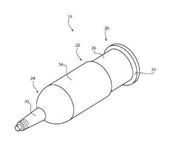
  • A61M 5/178 (2006.01)
  • A61M 5/30 (2006.01)
  • A61M 5/31 (2006.01)
(72) Inventors :
  • CUDE, MICHAEL J. (United States of America)
(73) Owners :
  • COEUR, INC. (United States of America)
(71) Applicants :
  • COEUR, INC. (United States of America)
(74) Agent: FINLAYSON & SINGLEHURST
(74) Associate agent:
(45) Issued: 2017-08-29
(86) PCT Filing Date: 2013-08-13
(87) Open to Public Inspection: 2014-02-20
Examination requested: 2015-02-13
Availability of licence: N/A
(25) Language of filing: English

Patent Cooperation Treaty (PCT): Yes
(86) PCT Filing Number: PCT/US2013/054676
(87) International Publication Number: WO2014/028452
(85) National Entry: 2015-02-13

(30) Application Priority Data:
Application No. Country/Territory Date
61/683,625 United States of America 2012-08-15

Abstracts

English Abstract

A syringe for a power injector includes a barrel having a distal end and a proximal end. The barrel defines an interior volume therebetween the distal and proximal ends. A circumferential flange extends about the proximal end. A delivery tip extends from the distal end. The barrel includes a thick wall section adjacent the distal end and a thin wall section adjacent the proximate end.


French Abstract

Seringue pour injecteur sous pression comprenant un corps ayant une extrémité distale et une extrémité proximale, ledit corps définissant un volume intérieur entre lesdites extrémités distale et proximale. Un embout pour l'administration s'étend à partir de l'extrémité distale. Le corps comporte une partie de paroi épaisse adjacente à l'extrémité distale et une partie de paroi mince adjacente à l'extrémité proximale.

Claims

Note: Claims are shown in the official language in which they were submitted.

WHAT IS CLAIMED IS:
1. A syringe (14) for a medical power injector (12) comprising:
a barrel (22) having a distal end (24) and a proximal end (26) and defining an
interior
volume (28) therebetween;
a delivery tip (32) extending from the distal end (24),
wherein the barrel (22) includes a thick wall section (34) adjacent the distal
end (24)
and a thin wall section (36) adjacent the proximate end (26), and
wherein the syringe (14) further comprises a circumferential flange (30)
extending
about the proximal end (26), and the syringe (14) is a jacketless syringe,
wherein the thick
wall section (34) and the thin wall section (36) have the same inner diameter.
2. A medical system (10) for injecting a fluid comprising:
a syringe (14) as defined in claim 1; and
a power injector (12) with a ram (18) for pushing fluid from the syringe (14).
3. The system of claim 2 further comprising:
a plunger (20) and a plunger jacket (16) engaging the ram (18) and disposed
within
the syringe (14).
4. The system of claim 3 wherein the barrel (22) defines a common inner
surface (38)
for engagement of the plunger jacket (16) shared by the thick wall section
(34) and the thin
wall section (36).
5. The system of any one of claims 2 to 4, wherein the syringe (14) is
formed from
thermo-plastic.

6. The system of claim 5, wherein the thermo-plastic is polypropylene.
7. The system of any one claims 2 to 6, wherein the thick wall section (34)
has a greater
pressure capability than the thin wall section.
8. The system of any one of claims 2 to 7, wherein the thick wall section
(34) has a
pressure capability of at least 3, 17 MPa (460 psi).
9. The system of any one of claims 2 to 8, wherein the thin wall section
(36) has a
pressure capability of at least 2, 59 MPa (375 psi).
6

Description

Note: Descriptions are shown in the official language in which they were submitted.


CA 02889313 2016-08-12
SYRINGE
BACKGROUND
[0002] This invention relates in general to medical injection systems.
[0003] One type of medical injection system includes a syringe and a power-
driven
injector. For example, for intravenous delivery the syringe may be filled with
fluid to
delivery and the syringe may be connected to a patient by appropriate tubing
and a needle.
Typically, in such an arrangement, the injector will include a plunger which
engages a
plunger jacket inside the syringe to push fluid from the syringe to a patient.
[0004] Such syringes are typically made of plastic. Due to the high
pressures generated
during the delivery process such syringes may include an outer pressure
jacket.
Alternatively, a syringe with a relatively thicker outer wall may be used and
then not include
an outer pressure jacket.
SUMMARY
[0005] This invention relates more specifically to syringes for medical
injection
systems.
[0006] In one embodiment a syringe for a power injector includes a barrel
having a
distal end and a proximal end. The barrel defines an interior volume
therebetween the distal
and proximal ends. A circumferential flange extends about the proximal end. A
delivery tip
1

CA 02889313 2015-02-13
WO 2014/028452 PCT/US2013/054676
extends from the distal end. The barrel includes a thick wall section adjacent
the distal end
and a thin wall section adjacent the proximate end.
[0007] The syringe may defines a common inner surface for engagement of a
plunger
jacket shared by the thick wall section and the thin wall section.
[0008] The syringe may be formed from thermo-plastic, such as
polypropylene.
[0009] The thick wall section may have a greater pressure capability than
the thin wall
section. The thick wall section may have a pressure capability of at least 460
psi. The thin
wall section may have a pressure capability of at least 375 psi.
[0010] Various aspects will become apparent to those skilled in the art
from the
following detailed description and the accompanying drawings.
BRIEF DESCRIPTION OF THE DRAWINGS
[0011] Fig. 1 is a perspective view of a injection system as shown in
exploded view.
[0012] Fig. 2 is an enlarged perspective view of the syringe of Fig. 1.
[0013] Fig. 3 is a cross-sectional view of the syringe of Fig. 2.
DETAILED DESCRIPTION
[0014] Referring now to the drawings, there is illustrated in Fig. 1 an
injection system
10. The system 10 includes a power driven injector 12 and a syringe 14. A
plunger jacket 16
is optionally disposed within the syringe 14. The injector 12 includes a ram
18 that drives a
plunger 20 that engages the plunger jacket 16 and thus may push fluid from the
syringe 14.
2

CA 02889313 2015-02-13
WO 2014/028452 PCT/US2013/054676
[0015] As best shown in Figs 2 and 3, the syringe 14 includes a barrel 22.
The barrel 22
has a distal end 24 and a proximal end 26. The barrel 22 defines an interior
volume 28
therebetween the distal end 24 and the proximal end 26. A circumferential
flange 30 extends
about the proximal end 26. A delivery tip 32 extends from the distal end 24.
[0016] The barrel 22 includes a thick wall section 34 adjacent the distal
end 24. The
barrel 22 includes a thin wall section 36 adjacent the proximate end 26. The
thick wall
section 34 and the thin wall section 36 are generally thick and thin
respectively relative to
one another. The thick wall section 34 and the thin wall section 36 share a
common inner
surface 38 for engagement of the plunger jacket 16.
[0017] In one embodiment the syringe 14 is formed from an olefin or thermo-
plastic,
such as Polypropylene.
[0018] The thick wall section 34 has a greater pressure capability than the
thin wall
section 36. For example the thick wall section 34 may be rated to 460 psi
while the thin wall
section 36 is rated for 375 psi. Thus in at least one embodiment the thick
wall section may
have a pressure capability of at least 460 psi, and in at least one embodiment
the thin wall
section may have a pressure capability of at least 375 psi.
[0019] It has been discovered that the pressure of a fluid in the interior
volume 28
increases as the plunger 20 and plunger jacket 16 move along the axial length
of the barrel 22
from the proximal end 26 toward the distal end 24. In operation the syringe 14
with a
syringe jacket, i.e. a jacketless syringe, may withstand greater pressure in
use than an
otherwise thinner unjacketed syringe, while having a relatively thinner wall
section adjacent
the proximate end.
[0020] In one operation, the syringe 14 is filled with a fluid for an
injection operation.
The syringe 14 with plunger jacket 16, the plunger 20, and without a syringe
jacket, is
loaded on the power driven injector 12 with the ram 18 engaging the plunger 20
and the
3

CA 02889313 2015-02-13
WO 2014/028452 PCT/US2013/054676
plunger jacket 16 to push fluid from the syringe 14 with the pressure in the
syringe increasing
as the ram 18 moves along the syringe 14.
[0021] While principles and modes of operation have been explained and
illustrated
with regard to particular embodiments, it must be understood, however, that
this may be
practiced otherwise than as specifically explained and illustrated without
departing from its
spirit or scope.
4

Representative Drawing
A single figure which represents the drawing illustrating the invention.
Administrative Status

For a clearer understanding of the status of the application/patent presented on this page, the site Disclaimer , as well as the definitions for Patent , Administrative Status , Maintenance Fee  and Payment History  should be consulted.

Administrative Status

Title Date
Forecasted Issue Date 2017-08-29
(86) PCT Filing Date 2013-08-13
(87) PCT Publication Date 2014-02-20
(85) National Entry 2015-02-13
Examination Requested 2015-02-13
(45) Issued 2017-08-29

Abandonment History

There is no abandonment history.

Maintenance Fee

Last Payment of $263.14 was received on 2023-08-04


 Upcoming maintenance fee amounts

Description Date Amount
Next Payment if standard fee 2024-08-13 $347.00
Next Payment if small entity fee 2024-08-13 $125.00

Note : If the full payment has not been received on or before the date indicated, a further fee may be required which may be one of the following

  • the reinstatement fee;
  • the late payment fee; or
  • additional fee to reverse deemed expiry.

Patent fees are adjusted on the 1st of January every year. The amounts above are the current amounts if received by December 31 of the current year.
Please refer to the CIPO Patent Fees web page to see all current fee amounts.

Payment History

Fee Type Anniversary Year Due Date Amount Paid Paid Date
Request for Examination $800.00 2015-02-13
Application Fee $400.00 2015-02-13
Registration of a document - section 124 $100.00 2015-04-13
Maintenance Fee - Application - New Act 2 2015-08-13 $100.00 2015-07-20
Maintenance Fee - Application - New Act 3 2016-08-15 $100.00 2016-07-19
Final Fee $300.00 2017-07-04
Maintenance Fee - Application - New Act 4 2017-08-14 $100.00 2017-07-19
Maintenance Fee - Patent - New Act 5 2018-08-13 $200.00 2018-08-06
Maintenance Fee - Patent - New Act 6 2019-08-13 $200.00 2019-08-09
Maintenance Fee - Patent - New Act 7 2020-08-13 $200.00 2020-08-07
Maintenance Fee - Patent - New Act 8 2021-08-13 $204.00 2021-08-06
Maintenance Fee - Patent - New Act 9 2022-08-15 $203.59 2022-08-05
Maintenance Fee - Patent - New Act 10 2023-08-14 $263.14 2023-08-04
Owners on Record

Note: Records showing the ownership history in alphabetical order.

Current Owners on Record
COEUR, INC.
Past Owners on Record
None
Past Owners that do not appear in the "Owners on Record" listing will appear in other documentation within the application.
Documents

To view selected files, please enter reCAPTCHA code :


To view images, click a link in the Document Description column. To download the documents, select one or more checkboxes in the first column and then click the "Download Selected in PDF format (Zip Archive)" or the "Download Selected as Single PDF" button.

List of published and non-published patent-specific documents on the CPD .

If you have any difficulty accessing content, you can call the Client Service Centre at 1-866-997-1936 or send them an e-mail at CIPO Client Service Centre.


Document
Description 
Date
(yyyy-mm-dd) 
Number of pages   Size of Image (KB) 
Abstract 2015-02-13 1 50
Claims 2015-02-13 3 75
Drawings 2015-02-13 3 30
Description 2015-02-13 4 115
Representative Drawing 2015-02-13 1 5
Cover Page 2015-05-13 1 29
Description 2016-08-12 4 109
Claims 2016-08-12 2 40
Final Fee 2017-07-04 1 30
Representative Drawing 2017-08-01 1 4
Cover Page 2017-08-01 1 31
PCT 2015-02-13 5 195
Assignment 2015-02-13 4 111
PCT 2015-02-20 1 30
Assignment 2015-04-13 5 171
Assignment 2015-02-13 6 166
Examiner Requisition 2016-02-18 5 288
Amendment 2016-08-12 6 142