Note: Descriptions are shown in the official language in which they were submitted.
CA 02889447 2015-04-27
COOPERATIVE MULTIDIRECTIONAL FLUID INJECTION AND ENHANCED
DRAINAGE LENGTH IN THERMAL RECOVERY OF HEAVY OIL
FIELD OF THE INVENTION
[0001] The invention is in the field of hydrocarbon reservoir engineering,
particularly
thermal recovery processes related to aspects of steam assisted gravity
drainage
(SAGD), cyclic steam stimulation (CSS) and steam flooding systems in heavy oil
reservoirs.
BACKGROUND OF THE INVENTION
[0002] Some subterranean deposits of viscous hydrocarbons can be extracted
in situ
by lowering the viscosity of the petroleum to mobilize it so that it can be
moved to, and
recovered from, a production well. Reservoirs of such deposits may be referred
to as
reservoirs of heavy hydrocarbon, heavy oil, bitumen, tar sands, or oil sands.
The in situ
processes for recovering oil from oil sands typically involve the use of
multiple wells
drilled into the reservoir, and are assisted or aided by injecting a heated
fluid such as
steam into the reservoir formation from an injection well, for example, in
SAGD, CSS or
steam flooding processes.
[0003] A typical SAGD process is disclosed in Canadian Patent No. 1,130,201
issued on 24 August 1982, in which two wells are drilled into the deposit, one
for
injection of steam and one for production of oil and water. Steam is injected
via the
injection well to heat the formation. The steam condenses and gives up its
latent heat
to the formation, heating a layer of viscous hydrocarbons. The viscous
hydrocarbons
are thereby mobilized, and drain by gravity toward the production well with an
aqueous
condensate. In this way, the injected steam initially mobilises the in-place
hydrocarbon
to create a "steam chamber" in the reservoir around and above the horizontal
injection
well. The term "steam chamber" accordingly refers to the volume of the
reservoir which
is saturated with injected steam and from which mobilized oil has at least
partially
drained. Mobilized viscous hydrocarbons are recovered continuously through the
production well. The conditions of steam injection and of hydrocarbon
production may
be modulated to control the growth of the steam chamber, to ensure that the
production
1
CA 02889447 2015-04-27
well remains located at the bottom of the steam chamber in an appropriate
position to
collect mobilized hydrocarbons.
[0004] The start-up stage of the SAGD process establishes thermal or
hydraulic
communication, or both, between the injection and production wells. At initial
reservoir
conditions, there is typically negligible fluid mobility between wells due to
high bitumen
viscosity. Communication is achieved when bitumen between the injector and
producer
is mobilized to allow for bitumen production. A conventional start-up process
involves
establishing interwell communication by simultaneously circulating steam
through each
injector well and producer well. High-temperature steam flows through a tubing
string
that extends to the toe of each horizontal well. The steam condenses in the
well,
releasing heat and resulting in a liquid water phase which flows back up the
casing-
tubing annulus. Alternative start-up techniques involve creating a high
mobility inter-well
path using solvents or by application of pressures so as to dilate the
reservoir sand
matrix, as for example disclosed in Canadian Patent No. 2,757,125.
[0005] In the ramp-up stage of the SAGD process, after communication has
been
established between the injection and production wells during start-up
(usually over a
limited section of the well pair length), production begins from the
production well.
Steam is continuously injected into the injection well (usually at constant
pressure) while
mobilized bitumen and water are continuously removed from the production well
(usually at constant temperature). During this period the zone of
communication
between the wells is expanded axially along the full well pair length and the
steam
chamber grows vertically up to the top of the reservoir. The reservoir top may
be a thick
shale (overburden) or some lower permeability facies that causes the steam
chamber to
stop rising. When the interwell region over the entire length of the well pair
has been
heated and the steam chamber that develops has reached the reservoir top, the
bitumen production rate typically peaks and begins to decline while the steam
injection
rate reaches a maximum and levels off.
[0006] In conventional SAGD, after ramp-up, in an operational phase of
production,
the steam chamber has generally achieved full height (although it is typically
still rising
2
CA 02889447 2015-04-27
slowly through or spreading around lower permeability zones in some locations)
and
lateral or radial growth of the steam chamber along the longitudinal axis of
the well pair
becomes the dominant mechanism for recovering bitumen. Typically steam
injection at
the injector well is controlled so as to maintain a target steam chamber
pressure during
this phase. As the emulsion drains to the production well, fluid withdrawal
rates are
controlled to ensure the well remains submerged in bitumen and steam
condensate.
Submergence prevents the steam that overlies the liquid zone from breaking
through to
the production well, which can short-circuit the SAGD process and potentially
damage
the wellbore. In certain instance submergence is not achieved along the entire
of length
of the well bore. This may be due to reservoir heterogeneity, such as pay,
permeability
or saturation differences, and well bore hydraulic issues imposed by the
trajectory or
completion design. In some cases, the reservoir may be characterized by
heterogeneities that require modifications to the recovery processes, such as
a gas cap
or a top or bottom water zone.
[0007] A concomitant of a thermal recovery process applied to an oil sand
is that
non-condensing gases (NCGs) are evolved and created. In a typical
implementation of
SADG, there are a number of sources of NCGs within the steam chamber. One
source
is the evolution of solution gas dissolved in the bitumen. As the bitumen is
heated the
solubility of the gas decreases as it becomes energized, resulting in its
evolution from
the bitumen into the steam chamber. A second major source involves the
production of
NCGs from reactions taking place between water and organic compounds at
elevated
temperatures and pressures. This process can for example include bitumen
thermal
cracking at elevated temperatures or low temperature oxidation. Other minor
sources of
NCGs may include the co-injection of gases with steam, for example as may be
undertaken in order to prevent steam hammer or for the purpose of using the
NCG to
facilitate measurements of the steam chamber pressure.
[0008] NCGs in the steam chamber can offer both benefits and challenges to
the
optimal performance of a SAGD system. For example, US Patent No. 8,596,357
describes methods for adding a buoyancy-modifying agent to injected steam,
such as
an additional NCG, to help cause NCGs to accumulate at the top of the steam
chamber.
3
CA 02889447 2015-04-27
This approach reflects the fact that NCGs tend to be light and therefore
buoyant, so that
any NCG that is liberated or generated lower in the steam chamber will tend to
rise to a
higher part of the steam chamber, and any NCG produced or released higher in
the
steam chamber will tend to remain in the upper elevations of the steam
chamber. Other
aspects of fluid dynamics in the SAGD process influence this vertical NCG
flow. For
example, as injected steam migrates from the injection well to the steam
chamber walls,
the steam in effect drags NCGs with it, and as it condenses and transfers heat
to the
bitumen, the volume formerly occupied by steam is significantly reduced. This,
in
combination with various factors, including the fact that NGCs generally have
much
greater vapour pressures compared to steam at lower temperatures, creates a
region
that can draw NCGs to the margins of the steam chamber.
[0009] Accordingly, a combination of their non-condensable nature,
buoyancy,
source and the lower relative pressures at the steam bitumen interface,
generally leads
to NCG accumulation high in the steam chamber near the walls. This poses
challenges,
in the sense that the NCGs may act as an insulator, lowering the partial
pressure of the
steam and therefore the saturation temperature, thus inhibiting lateral growth
of the
steam chamber. In addition, it may make it difficult to remove the NCGs in a
conventional SAGD operation, where the single source of production is a well
located at
the bottom of the steam chamber.
[0010] The management of NCGs is further complicated by the fact that
gravity-
dominated in situ recovery processes, such as SAGD, rely on vertical flow and
displacement. However, given the long horizontal wells that are normally
associated
with this type of process, and the (axial) flows along the length of the
wells, the resulting
(radial or transverse) flows from reservoir to well, and vice versa, will tend
to be non-
uniform, even in a homogeneous reservoir.
[0011] In the context of the present application, various terms are used in
accordance with what is understood to be the ordinary meaning of those terms.
For
example, "petroleum" is a naturally occurring mixture consisting predominantly
of
hydrocarbons in the gaseous, liquid or solid phase. In the context of the
present
4
CA 02889447 2015-04-27
application, the words "petroleum" and "hydrocarbon" are used to refer to
mixtures of
widely varying composition. The production of petroleum from a reservoir
necessarily
involves the production of hydrocarbons, but is not limited to hydrocarbon
production.
Similarly, processes that produce hydrocarbons from a well will generally also
produce
petroleum fluids that are not hydrocarbons. In accordance with this usage, a
process for
producing petroleum or hydrocarbons is not necessarily a process that produces
exclusively petroleum or hydrocarbons, respectively. "Fluids", such as
petroleum fluids,
include both liquids and gases. Natural gas is the portion of petroleum that
exists either
in the gaseous phase or is in solution in crude oil in natural underground
reservoirs, and
which is gaseous at atmospheric conditions of pressure and temperature.
Natural Gas
may include amounts of non-hydrocarbons. The abbreviation POIP stands for
"producible oil in place" and in the context of the methods disclosed herein
is generally
defined as the exploitable or producible oil structurally located above the
production well
elevation.
[0012] It is common practice to segregate petroleum substances of high
viscosity
and density into two categories, "heavy oil" and "bitumen". For example, some
sources
define "heavy oil" as a petroleum that has a mass density of greater than
about 900
kg/m3. Bitumen is sometimes described as that portion of petroleum that exists
in the
semi-solid or solid phase in natural deposits, with a mass density greater
than about
1000 kg/m3 and a viscosity greater than 10,000 centipoise (cP; 01 10 Pa.$)
measured at
original temperature in the deposit and atmospheric pressure, on a gas-free
basis.
Although these terms are in common use, references to heavy oil and bitumen
represent categories of convenience, and there is a continuum of properties
between
heavy oil and bitumen. Accordingly, references to heavy oil and/or bitumen
herein
include the continuum of such substances, and do not imply the existence of
some fixed
and universally recognized boundary between the two substances. In particular,
the
term "heavy oil" includes within its scope all "bitumen" including
hydrocarbons that are
present in semi-solid or solid form.
[0013] A reservoir is a subsurface formation containing one or more natural
accumulations of moveable petroleum, which are generally confined by
relatively
CA 02889447 2015-04-27
impermeable rock. An "oil sand" or "tar sand" reservoir is generally comprised
of strata
of sand or sandstone containing petroleum. A "zone" in a reservoir is merely
an
arbitrarily defined volume of the reservoir, typically characterised by some
distinctive
property. Zones may exist in a reservoir within or across strata, and may
extend into
adjoining strata. In some cases, reservoirs containing zones having a
preponderance of
heavy oil are associated with zones containing a preponderance of natural gas.
This
"associated gas" is gas that is in pressure communication with the heavy oil
within the
reservoir, either directly or indirectly, for example through a connecting
water zone.
[0014] A "chamber" within a reservoir or formation is a region that is in
fluid
communication with a particular well or wells, such as an injection or
production well.
For example, in a SAGD process, a steam chamber is the region of the reservoir
in fluid
communication with a steam injection well, which is also the region that is
subject to
depletion, primarily by gravity drainage, into a production well.
[0015] A "multilateral well" is a well that has a plurality of branches, or
"laterals"
deviating from the initial well bore, with a wide variety of completion
options available in
alternative situations (see "Multilateral Wells" A.D. Hill, Ding Zhu & Michael
J.
Economides, 2008, ISBN:978-1-55563-138-3, Society of Petroleum Engineers).
SUMMARY OF THE INVENTION
[0016] In one aspect, the present invention utilizes cooperating
multilateral wells to
improve the performance of a SAGD process. One effect of an arrangement of
wells
contemplated by the present invention is an adjustment to fluid flow patterns
in the
recovery process, which may in some cases have the effect of addressing the
challenge
of beneficially removing from the reservoir significant quantities of NCG.
[0017] In various aspects, the invention provides processes and systems for
removing fluids from a subterranean formation, particularly a hydrocarbon
reservoir
bearing a heavy oil. As is typical, the reservoir may be defined by an
uppermost extent
of heavy oil at a reservoir top, and a lowermost extent of heavy oil at a
reservoir bottom.
6
CA 02889447 2015-04-27
A well pair may be emplaced within the reservoir, having surface completions
and one
or more well bores extending downwardly towards the bottom of the reservoir.
The well
pair typically descends generally vertically to a heel transition segment
connecting the
well bore with the generally horizontal longitudinal axial dimension of the
well pair. The
horizontal portion of the well pair is typically made up of a generally
horizontal segment
of a well pair production well, and a generally horizontal segment of an
injection well.
These horizontal wells extend longitudinally within the reservoir in fluid
communication
with the well pair surface completion through the well pair bore. The
horizontal segment
of the injection well is generally parallel to and vertically spaced apart
above the
horizontal segment of the well pair production well.
[0018] In one aspect of the invention, the horizontal segment of an
injection well may
be completed with one or more multilateral arms that extend transversely and
laterally
away from the longitudinal axial dimension of the well pair. As such, the
horizontal
segment of the injection well and the multilateral arms thereof lie generally
on a
horizontal plane within the reservoir, which may be defined as a horizontal
multilateral
injection well plane.
[0019] Embodiments of the invention may include a multilateral production
well
laterally spaced apart from an adjacent well pair. The multilateral production
well will
typically have a surface completion, a wellbore extending generally vertically
downwardly from the surface towards the bottom of the reservoir, and a heel
transition
leading into a generally horizontal segment of the multilateral production
well. As such,
the horizontal portion of the multilateral production well extends
longitudinally within the
reservoir generally parallel to and laterally spaced apart from the
longitudinal axial
dimension of the adjacent well pair. The horizontal segment of the
multilateral
production well may have one or more multilateral arms, each extending
transversely
and laterally away from the horizontal segment of the multilateral production
well
towards the adjacent well pair.
[0020] The multilateral arms of the multilateral production well may
include segments
that are generally parallel to and vertically spaced apart below a
corresponding
7
CA 02889447 2015-04-27
multilateral arm of the multilateral injection well. There may also be lateral
segments of
these multilateral wells that are not parallel, for example where segments of
the
corresponding lateral production and injection arms cross. Arranged in this
way, the
horizontal segment of the multilateral production well and the multilateral
arms thereof
lie generally on a horizontal plane, that may be defined as the multilateral
production
well plane. This plane may be generally parallel to, and vertically spaced
apart below,
the horizontal multilateral injection well plane.
[0021] In operation, the foregoing arrangement of wells may be utilized in
a SAGD
process by injecting an injection fluid through the multilateral injection
well, so as to
mobilize the heavy oil, and recovering the mobilized heavy oil from the
reservoir through
the production well of the well pair and through the multilateral production
well.
[0022] A repeating pattern of injection and production wells may be
emplaced within
a reservoir, effectively multiplying the pattern described above. For example,
a second
well pair may be laterally spaced apart from the multilateral production well,
so that the
multilateral production well is located between first and second well pairs.
As such, the
second well pair will include a second multilateral injection well that forms
a second
horizontal multilateral injection well plane that is generally coplanar with
the first
horizontal multilateral injection well plane. Multilateral arms of the
multilateral production
well may similarly extend transversely and laterally away from the horizontal
segment of
the multilateral production well towards the second well pair, with
multilateral arms of
the multilateral production well having segments that are generally parallel
to and
vertically spaced apart below a corresponding multilateral arm of the second
multilateral
injection well. In select embodiments, multilateral arms may be spaced apart
along the
horizontal segment of the multilateral production well so that the
multilateral arms
alternate between extending towards the first well pair and the second well
pair.
[0023] A repeating pattern of additional cooperating multilateral
production wells and
well pairs may be used to forming cooperating adjacent generally horizontal
multilateral
injection well planes spaced apart above corresponding generally parallel
cooperating
adjacent horizontal multilateral production well planes. In this way,
cooperating injection
8
CA 02889447 2015-04-27
well planes and production well planes combining to form a generally
continuous set of
cooperating tiled injection and production well planes, blanketing the bottom
of the
reservoir. Within this arrangement, the multilateral arms of the multilateral
injection wells
and the multilateral production wells may be spaced apart along the horizontal
segments thereof so as to form an offset grid of interdigitating multilateral
well
segments, with multilateral wells that are generally perpendicular to the
longitudinal
axial dimensions of the cooperating well pairs.
[0024] In one aspect of the invention, the foregoing arrangement of wells
may be
operated so that non-condensing gases are produced with the mobilized heavy
oil, for
example being driven along deliberate pressure gradients so as to be
preferentially
produced at the offset production well. This may have the effect of improving
production, by virtue of minimizing the insulating effect of NCGs that might
otherwise
accumulate at the margin of the steam chambers. In alternative embodiments,
NCGs
may be co-injected (as for example described in Canadian Patent Application
No.
2,827,772), for example in such a way as to reduce the volume of steam
required to
produce a given amount of oil, thereby reducing the CSOR. Similarly, solvents
may be
used alone or in combination with other injection fluids, such as surfactants.
Injection
fluids may also be selected so as to initiate and/or support in situ
combustion within the
reservoir.
BRIEF DESCRIPTION OF THE DRAWINGS
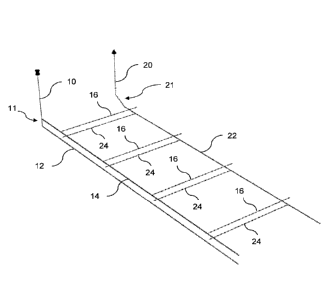
[0025] Figure 1 is schematic illustration of a well pattern, showing a pair
of injector
and producer wells in a well pair, in which the injector is a multilateral
well having lateral
arms. The longitudinal axis of the well pair is offset from a generally
parallel adjacent
multilateral production well, with the lateral arms of the multilateral
production well
underlying the multilateral arms of the injection well of the well pair.
Together, the
multilateral arms of the injection and production wells form cooperating well
pairs.
[0026] Figure 2 is a schematic illustration of a well pattern, based upon
the
arrangement shown in Figure 1, showing an additional well pair adjacent to the
9
CA 02889447 2015-04-27
multilateral production well. The lateral arms of the multilateral production
well alternate
between extending towards the first well pair and the second well pair.
[0027] Figure 3 is an isometric illustration in cross section, comparing
the
temperature profiles of steam chambers formed in simulated use of the
injection and
production well arrangement of Figure 1, as shown in Figure 3A, as compared to
a
typical SAGD well pair operated under comparable conditions, shown in Figure
3B.
[0028] Figure 4 is an isometric illustration in cross section, comparing
the reservoir
oil saturation in simulated reservoirs that correspond generally to the
reservoirs
illustrated in Figure 3, with the oil saturation resulting from use of the
injection and
production well arrangement of Figure 1 shown in Figure 4A, as compared to the
oil
saturation resulting from use of a typical SAGD well pair operated under
comparable
conditions, shown in Figure 4B.
[0029] Figure 5 is a graph illustrating the half oil production and half
water injection
rates for the simulated well configuration of Figure 1, solid lines, compared
to the
corresponding rates for the conventional SAGD well pair illustrated in Figures
3B and
4B, dashed lines.
[0030] Figure 6 is a graph illustrating the oil recovery factor over time
for the
simulated well configuration of Figure 1, top line, compared to the
conventional SAGD
well pair illustrated in Figures 3B and 4B, bottom line.
[0031] Figure 7 is a graph illustrating the cumulative steam oil ratio over
time for the
simulated well configuration of Figure 1, solid line, compared to the
conventional SAGD
well pair illustrated in Figures 3B and 4B, dashed line.
[0032] Figure 8 is a graph illustrating gas production over time for the
simulated well
configuration of Figure 1, through the multilateral production well (solid
line) compared
to the non-multilateral production well (circles), compared for reference to
the
cumulative gas production in the SAGD producer (dashed line).
CA 02889447 2015-04-27
[0033] Figure 9 is a graph illustrating oil rates achieved in alternative
embodiments
in which there are laterally offset injection and production wells, neither of
which are
paired in a SAGD well pair arrangement, Case 1 (solid line) and Case 2
(circles),
compared to a SAGD well pair (dashed line).
[0034] Figure 10 is a graph illustrating cumulative oil production in the
well
arrangement as described for Figure 9, with Case 1 (solid line) and Case 2
(circles)
compared to a SAGD well pair (dashed line).
[0035] Figure 11 is a graph illustrating cumulative gas production in the
well
arrangement as described for Figure 9, with Case 1 (solid line) and Case 2
(circles)
compared to a SAGD well pair (dashed line).
[0036] Figure 12 is a graph illustrating oil recovery factor in the well
arrangement as
described for Figure 9, with Case 1 (solid line) and Case 2 (circles) compared
to a
SAGD well pair (dashed line).
[0037] Figure 13 is a sectional view of a partially completed multilateral
well.
[0038] Figure 14 is of the multilateral well of Figure 8, further along in
the completion
process.
[0039] Figure 15 is a graph illustrating oil viscosity as a function of
temperature in a
computational model of alternative embodiments of the invention.
[0040] Figure 16 is a graph illustrating the solution gas ratio as function
of pressure
at a reference temperature of 12 C in a computational model of alternative
embodiments of the invention.
[0041] Figure 17 is a graph illustrating the oil-water relative
permeability curves in a
computational model of alternative embodiments of the invention, with water
saturation
11
CA 02889447 2015-04-27
on the X axis, showing relative oil permeability decreasing with increasing
water.
saturation (dashed line) and relative water permeability increasing with water
saturation
(solid line).
[0042] Figure 18 is a graph illustrating the Oil-Gas relative permeability
curves in a
computational model of alternative embodiments of the invention.
[0043] Figure 19 is a schematic illustration of three alternative well
patterns,
showing pairs of injector (I) and producer (P) wells in well pairs, in which
the injector (I)
is a multilateral well having lateral arms, with intermediate multilateral
production wells
(P) situated between well pairs. The longitudinal axis of each well pair is
offset from a
generally parallel adjacent intervening multilateral production well, with the
lateral arms
of the multilateral production well underlying the multilateral arms of the
injection wells
of the well pairs. Together, the multilateral arms of the injection and
production wells
form cooperating well pairs.
DETAILED DESCRIPTION OF THE INVENTION
[0044] Various aspects of the invention involve the drilling and completion
of
injection and production wells within a heavy oil reservoir, such as SAGD well
pairs. As
illustrated in Figure 1, a well pair may have injector and producer wells with
completions
that share a vertical well bore 10, although in practice there will typically
be separate
vertical well bores for each of the injection and production wells. A heel
transition region
11 connects the generally vertical portion of the wells 10 to the generally
horizontal
segments of the injector 14 and producer 12, each culminating at the toe of
the
respective well. The horizontal portion of injector 14 may be provided with
multilateral
arms 16, extending transversely and laterally away from the longitudinal axial
dimension
of the well pair. In this arrangement, the horizontal segment of the injection
well 14 and
the multilateral arms thereof 16 lie generally on a plane, which may be
defined as a
horizontal multilateral injection well plane.
12
CA 02889447 2015-04-27
[0045] Figure 1 illustrates a multilateral production well that cooperates
with the
adjacent well pair. The multilateral production well is laterally spaced apart
from the
cooperating well pair, with a well bore 20 extending generally vertically
downwardly from
a surface completion towards the bottom of the reservoir. The heel 21 of the
multilateral
production well connects the well bore 20 with a generally horizontal segment
22 that
extends longitudinally within the reservoir generally parallel to and
laterally spaced apart
from the longitudinal axial dimension of the cooperating well pair. In
selected
embodiments, as illustrated, the heel of the production well may be landed
significantly
higher in the reservoir than the longitudinal horizontal segment of the well,
such as 5-
10m above the horizontal segment, and the heel may be completed so as to
facilitate
NCG production by providing elevated an elevated production segment of the
production well. Similar results may be obtained by alternative completions,
such as
perforating a lower portion of the production well bore, also providing an
elevated
production segment of the production well. The horizontal segment of the
multilateral
production well is completed with multilateral arms 24 that extend
transversely and
laterally away from horizontal well segment 22 towards the cooperating well
pair. The
multilateral arms 24 of the multilateral production well include segments that
are
generally parallel to and vertically spaced apart below the corresponding
multilateral
arms 16 of the multilateral injection well of the well pair. In this way, the
horizontal
segment 22 of the multilateral production well and the multilateral arms
thereof 24 lie
generally on a horizontal multilateral production well plane. This production
well plane is
generally parallel to, and vertically spaced apart below, the horizontal
multilateral
injection well plane.
[0046] Alternative arrangements of injection and production wells are
contemplated,
as for example shown in Figures 2 and 19, with at least one of the wells being
a
multilateral well with laterals that extend away from the longitudinal axis of
the well, to
create advantageous fluid flow dynamics. For example, as modeled below, an
unpaired
multilateral injection well may cooperate with a laterally offset non-
multilateral
production well. Similarly, an unpaired multilateral production well may
cooperate with a
laterally offset non-multilateral injection well. In either circumstance,
modelling illustrates
advantageous properties associated with the altered reservoir fluid flow
dynamics that
13
CA 02889447 2015-04-27
are associated with transverse segments of cooperating injection and
production wells.
Further alternatives relate to the expanded pattern of injection and
production wells. For
example, a single multilateral injection well may cooperate with multiple
production wells
by virtue of lateral injection arms that extend laterally across the
longitudinal path of
more than one production well. Similarly, long lateral arms of multilateral
production
wells may be provided so as to cooperate with multiple injection wells.
[0047] In very general terms, to provide a general illustration of scale in
selected
embodiments, these wells may for example be drilled and completed in
accordance with
the following parameters. There may be approximately 3-7m of depth separation
between the injection well and production well of a well pair, for example
averaging
approximately 5m. The SAGD well pair may for example be from 200m to 2000m, or
from 500m to 1000m, in length, for example being about 800m long. The lower
production well profile may generally be targeted so that it is close to the
bottom of the
reservoir, for example approximately 1 to 2 m above the lower extent of the
target
hydrocarbon deposit. The lateral offset of between wells in alternative
embodiments
may vary widely, for example from 10m to 400m. Alternative aspects of the
invention
involve completing wells in various configurations, as for example is
disclosed in
Canadian Patent No. 2,757,125 and Canadian Patent Application No. 2,721,342.
[0048] In accordance with various aspects of the invention, detailed
computational
simulations of reservoir behaviour have been carried out.
Simulation Grid
[0049] A half element of symmetry was employed to ensure faster run times. The
model had 30 m pay, 3 m gas cap pay and an 804 m long well. There was 31 m of
overburden and 31 m underburden. Grid dimensions were 25 x 210 x 33. Block
dimensions for the main reservoir were as follows:
I ¨ direction: 25*2 m (25 blocks, total length of 50 m)
J ¨ direction: 210*4.02m (210 blocks, total length of 804 m)
K ¨ direction: 16 m8m4m2m 33*1 m2m4m8m 16 m (41 blocks, total
length of 93 m).
, 14
CA 02889447 2015-04-27
[0050] Block dimensions for the over laying gas cap were as follows:
I ¨ 25*2m (25 blocks, total length of 50 m)
J ¨ direction: 2500 m 1000 m 500 m 100 m 10 m 200*4.02 m 10 m 100 m 500 m
1000 m 2500 m (210 blocks, total length of 9024 m)
K ¨ direction: 3*1 m (3 blocks, total length of 3 m)
[0051] The high level of discretization in the J direction was done to
provide relatively
similar heat transfer effects in I and J directions, ameliorating heat
transfer artifacts
along the main wellbore and along the laterals that might otherwise arise due
to
dissimilar grid sizes in both I and j directions. A typical casing joint is
approximately 12-
13 m in length.
Reservoir Properties
[0052] The grid was populated using the following reservoir variables:
Temperature = 12 C
(1) = 0.33
Kh = 7.0 D
Kv = 4.2 D
Reference pressure of 2,400 kPa at the top of the SAGD pay
Sw = 0.20
So = 0.80
Mass Fraction Oil of Dead Oil = 0.89
Mass Fraction Oil of CH4 = 0.11
[0053] The thermal properties of the reservoir were characterized using two
rock
types. Rock type one represented clean sand and was used to populate a
selected pay,
representing the McMurray formation in Alberta, Canada. A second rock type
representing shale was used to populate the over and underburden grid. The
properties
of the two rock types were defined with the following properties:
Rocktype 1 (Sand)
Porosity Reference Pressure = 100 kPa
CA 02889447 2015-04-27
Compressibility = le-6 1/kPa
Volumetric Heat Capacity 2.39e6 J/(m3*C)
Rock Thermal Conductivity = 196,820 J/(m*day*C)
Water Thermal Conductivity = 552,960 J/(m*day*C)
Oil Thermal Conductivity = 0
Gas Thermal Conductivity = 0
Rocktype 2 (Shale Overburden & Underburden)
Porosity Reference Pressure = 100 kPa
Compressibility = 1e6 1/kPa
Volumetric Heat Capacity 2.39e6 J/(m3*C)
Rock Thermal Conductivity = 146,880 J/(m*day*C)
Water Thermal Conductivity = 0
Oil Thermal Conductivity = 0
Gas Thermal Conductivity = 0
PVT Data
[0054] The PVT model consisted of three components; water, dead oil and
methane,
with characteristics as illustrated in Figures 15 and 16.
Relative Permeability
[0055] The oil-water relative permeability curves have the following
properties:
Connate Water Saturation = 0.2
Critical Water Saturation = 0.2
Residual Oil Saturation = 0.15
Irreducible Oil Saturation = 0.15
Max relative water permeability = 0.559
Max relative oil-water permeability = 0.95
[0056] The oil-gas relative permeability curves have the following
properties:
Critical Gas Saturation = 0.05
Residual Liquid Saturation = 0.3
16
CA 02889447 2015-04-27
Max relative gas permeability = 0.72
Max relative oil-gas permeability = 0.95
[0057] Relative permeability properties are illustrated in Figures 17 and
18.
Operating Constraints
[0058] The simulation was initiated using hot zone (temperature of 200 deg
C) to
replicate the circulation phase in order to establish inter wellpair
communication. Two
segmented wellbore models were used to mimic the operation of a SAGD well pair
during this phase. For the multilateral cases either two or three segmented
wellbore
models were used to mimic the operation of one or two multilateral wells and a
normal
SAGD-type producer during this phase. As exemplified, the SAGD operational
phase
begins after circulation, takes place at high pressure gas lift and then low
pressure ESP
stages and lasts until the start of blow down. During this period, the
segmented wellbore
models were defined with the following parameters and constraints in order to
mimic
SAGD and multilateral well operations:
SAGD Injector Annulus (Shutin)
ID = 0.159
OD = 0.178
Multilateral Injector Annulus (Shutin)
ID = 0.224
OD = 0.244
SAGD Injector Tubing String (Oprn)
ID = 0.104
OD = 0.134
Multilateral Injector Tubing String (Oprn)
ID = 0.124
OD = 0.154
Injector liner block 1, 6, 28 kept at 5,100 kPaa and 2,645 kPaa during gas
lift and ESP operating modes, respectively, via trigger
Injector Tubing String (Injector Well)
17
CA 02889447 2015-04-27
Max Bottom Hole Pressure initiated at 5,100 kPaa, but later defined via
trigger
Max Water Rate = 1,500 m3/d and 2000 m3/d for SAGD and multilateral
cases, respectively.
SAGD tubing has 3 steam splitters at following blocks:
1st Sub at block 1, 35, 28: 1 cm diameter holes, 0.9 discharge coefficient,
8 holes
2nd Sub at block 1, 85, 28: 1 cm diameter holes, 0.9 discharge coefficient,
14 holes
3rd Sub at block 1, 148, 28: 1 cm diameter holes, 0.9 discharge coefficient,
32 holes
Multilateral tubing has 5 steam splitters at following blocks:
1st Sub at block 1,25, 28: 1 cm diameter holes, 0.9 discharge coefficient,
4 holes
2nd Sub at block 1, 55, 28: 1 cm diameter holes, 0.9 discharge coefficient,
8 holes
3rd Sub at block 1, 105, 28: 1 cm diameter holes, 0.9 discharge coefficient,
14 holes
4th Sub at block 1, 155, 28: 1 cm diameter holes, 0.9 discharge coefficient,
28 holes
5th Sub at block 1, 185, 28: 1 cm diameter holes, 0.9 discharge coefficient,
32 holes
Producer Annulus (Producer Well)
Max Liquid Rate = 1500 m3/d
Min Bottom Hole Pressure = 2,000 kPa
Max Steam Production = 10 m3/d CWE
[0059] The foregoing simulation parameters were applied to illustrate the
performance of the well arrangement shown in Figure 1, compared to a SAGD well
pair
alone. These simulations accordingly reflect the implementation of a process
for
18
CA 02889447 2015-04-27
removing fluids from a heavy oil reservoir involving a well pair in which a
generally
horizontal segment of a well pair injection well 14 extends longitudinally
within the
reservoir in fluid communication with the well pair surface completion through
the well
pair bore 10. The horizontal segment of the well pair injection well 14 is
generally
parallel to and vertically spaced apart above the horizontal segment of the
well pair
production well 12. The horizontal segment of the well pair injection well 14
has one or
more multilateral arms 16 that extend transversely and laterally away from the
longitudinal axial dimension of the well pair. A multilateral production well
is laterally
spaced apart from the well pair, with a generally horizontal segment 22 having
one or
more multilateral arms 24 are generally parallel to and vertically spaced
apart below the
corresponding multilateral arms 16 of the multilateral injection well.
Utilizing this
arrangement of wells, an injection fluid such as steam may be injected through
the
multilateral injection well so as to mobilize the heavy oil, and the mobilized
heavy oil
may be recovered from the reservoir through the production well of the well
pair and
through the multilateral production well.
[0060] Figures 3-7 illustrate the cooperative effect of a well pair having
a multilateral
injector and an adjoining multilateral production well, in which the
multilateral arms of
the injector cooperate with the underlying multilateral arms of the producer
to facilitate
expansion of steam chambers both along the longitudinal axis of the well pair,
and
along the transverse dimension of the multilateral arms.
[0061] Figure 3A illustrates that as the injection fluid is injected
through the injection
well 14, 16 of the well pair, the multilateral production well steam chambers
expand in
fluid communication with the multilateral production well 22, 24, so as to
expand each
multilateral production well steam chamber both above the multilateral arms 24
of the
multilateral production well and above the generally horizontal segment of the
multilateral injection well 22. An area of longitudinal steam chamber
expansion above
the horizontal segment 22 is evident at region 40. The comparable steam
chamber
development in a typical SAGD well pair operated under comparable conditions
is
shown in Figure 3B.
19
CA 02889447 2015-04-27
[0062] Figure 4A illustrates the residual oil saturation corresponding to
the steam
chamber of Figure 3A, in which residual oil is evident in pillars 42 of
residual oil that
reside between the multilateral arms 24 of the multilateral production well.
As shown in
Figure 2, a second well pair 30, 31, 32, 34, 36 may be provided laterally
spaced apart
from the multilateral production well 20, 21, 22, 24, so that the multilateral
production
well is located between the first and second well pairs. The second well pair
includes a
second multilateral injection well that forms a second horizontal multilateral
injection
well plane, generally coplanar with the first horizontal multilateral
injection well plane
formed by the injection well 10, 11, 14, 16 of the first well pair. The
multilateral arms 24
of the multilateral production well extend transversely and laterally away
from the
horizontal segment 22 of the multilateral production well towards the second
well pair,
so that the multilateral arms 24 of the multilateral production well have
segments that
are generally parallel to and vertically spaced apart below a corresponding
multilateral
arm 36 of the second multilateral injection well. The multilateral arms 24 may
be spaced
apart along the horizontal segment of the multilateral production well 22 so
that the
multilateral arms 24 alternate between extending towards the first well pair
and the
second well pair. In this way, the pillars of residual oil 42 may be drained
by operation of
the alternating multilateral arms of production and injection wells. In this
arrangement,
the multilateral arms 16, 36 of the multilateral injection wells and the
multilateral arms
24 of the multilateral production wells are spaced apart along the horizontal
segments
thereof 12, 22, 32 so as to form an offset grid of interdigitating
multilateral well
segments that are generally perpendicular to the longitudinal axial dimensions
of the
cooperating well pairs.
[0063] Additional cooperating multilateral production wells and well pairs
may be
used, including infill wells as described in Canadian Patent No. 2,591,498, so
that
together these wells form cooperating adjacent generally horizontal
multilateral injection
well planes spaced apart above corresponding generally parallel cooperating
adjacent
horizontal multilateral production well planes. In this way, the cooperating
injection well
planes and production well planes combine to form a generally continuous set
of
cooperating tiled injection and production well planes along the bottom of the
reservoir.
CA 02889447 2015-04-27
[0064] Figure 5 graphs the oil production 54 and water injection rates 50
for the
simulated well configuration of Figure 1, compared to the corresponding oil
production
56 and water injection 52 rates for the conventional SAGD well pair
illustrated in Figures
3B and 4B, dashed lines. As is evident in Figure 5, oil production rates for
the
multilateral well system of Figure 1 are much higher early in the production
cycle.
[0065] Figure 6 illustrate the dramatic improvement in early oil recovery
factor for the
simulated well configuration of Figure 1, top line, compared to the
conventional SAGD
well pair illustrated in Figures 3B and 4B, bottom line.
[0066] Figure 7 illustrates an early reduction in the cumulative steam oil
ratio for the
simulated well configuration of Figure 1, solid line, compared to the
conventional SAGD
well pair illustrated in Figures 3B and 4B, dashed line. Over a longer time
frame, the
cumulative steam oil ratio for the simulated well configuration of Figure 1
rises slightly
above that of the conventional SAGD well pair. This is due to the fact that
both
producers are set to operate at a maximized steam rate of 10 sm3/d (full rate,
or 5
sm3/d half rate per well). As a result, in the case of multilateral well
embodiments, most
of the oil is produced in the first few years; afterwards the oil rate drops
sharply and as a
consequence the arbitrary 10 m3/d of steam is an excessive rate for the
resulting
operating conditions. In practice, the steam rate may be reduced, for example
to
approximately 1 m3/d or less, which would improve the CSOR for the
multilateral
embodiment compared to the SAGD case. Figure 8 illustrates the preponderance
of gas
production through the multilateral production well (solid line) compared to
the non-
multilateral production well (circles) in the well arrangement of Figure 1,
compared for
reference to the cumulative gas production in the SAGD producer (dashed line).
[0067] In alternative embodiments, process of the invention may utilize
laterally
offset injection and production wells, with no SAGD well pairs in the
arrangement.
Alternative embodiments of this kind were modeled with either:
Case 1 ¨ a multilateral injector spaced 50 m laterally apart from a non-
multilateral
producer, with multilateral arms of the injector projecting in the direction
of the
producer, with the multilateral injector and the producer on essentially the
same
21
CA 02889447 2015-04-27
plane (the producer being only about 1m above the multilateral injector, with
the
injector laterals projecting to terminal locations adjacent to the producer);
or,
Case 2 ¨ a multilateral producer spaced 50 m laterally apart from a non-
multilateral injector, with multilateral arms of the producer projecting in
the
direction of the injector to terminal locations adjacent to the injector, with
the
injector located 4m above the plane of the multilateral producer.
[0068] Figure 9 illustrates the oil rates achieved in Case 1 (solid line)
and Case 2
(circles), compared to a SAGD well pair (dashed line). Figure 10 illustrates
the
cumulative oil production of Case 1 (solid line) and Case 2 (circles) compared
to a
SAGD well pair (dashed line). Figure 11 illustrates the cumulative gas
production in
Case 1 (solid line) and Case 2 (circles) compared to a SAGD well pair (dashed
line).
Finally, Figure 12 illustrates the oil recovery factor for Case 1 (solid line)
and Case 2
(circles) compared to a SAGD well pair (dashed line).
[0069] In one aspect of the process, non-condensing gases may be produced
with
the mobilized heavy oil. Conditions may be adjusted to facilitate NCG
production, so as
to ameliorate the insulating effect that NCGs may otherwise have on the growth
of the
steam chambers. For example, adjacent production wells may be operated at
different
pressures, so as to create a pressure differential driving NCGs to a lower
pressure
production well. Similarly, in situ combustion processes may be used to
augment the
steam-flood-like effect of lateral well segments, creating lateral pressure
differentials to
drive reservoir fluid flows. In situ combustion may also be used as a stand-
alone
recovery process or as a stage within a recovery process that also includes
alternative
thermal recovery techniques.
[0070] In one aspect, processes of the invention may be employed so as to
avoid the
need for the high pressures sometime required in various stages of a SAGD
process,
for example by creating a dynamic flow of reservoir fluids that optimizes
production of
NCGs without using pressures above 3,500 kPa. Startup process of the invention
may
also be adapted for particular reservoirs, for example circulating fluids only
in the
22
CA 02889447 2015-04-27
longitudinal segment of a multilateral well, leaving the lateral segments
cold, as
opposed to starting up an entire multilateral well ¨ alternative process that
may be
described as "cold-wings" or "hot-wings".
[0071] In various aspects, the invention involves the use of multilateral
wells which
may be completed in a variety of ways. For example, one method of multilateral
well
completion for a well having first and second lateral bores involves
introducing a
hydraulic set liner hanger assembly into a cased main bore. The hydraulic set
liner
hanger assembly may include a first pipe assembly and a second pipe assembly
coupled to the hydraulic set liner hanger assembly. The first pipe assembly
may include
a first seal coupled to a distal end of a first pipe, the second pipe assembly
may include
a second seal coupled to a distal end of a second pipe, the second pipe being
longer
than the first pipe and the second seal having a larger outer diameter than
the first seal.
The hydraulic set liner hanger assembly may be advanced through the cased main
bore, the second seal abutting a deflecting surface of a hollow diverter
located in the
cased main bore and being directed into the second lateral bore to provide a
seal
between a second liner received in the second lateral bore and the second
pipe. The
first seal may pass through the hollow diverter to provide a seal between a
first liner
received in the first lateral bore and the first pipe, the deflecting surface
of the hollow
diverter being located adjacent to the second lateral bore. The hydraulic set
liner may
then be set in the cased main bore.
[0072] Figures 13 and 14 illustrate aspects of completed multilateral
wells, which
involve deploying multiple pipes to form seals with an inlet portion of dual
crossover 60
and liner 92 of lateral bore 90. A completion of this kind may for example be
deployed
as follows. First, hollow deflector 110 may be run down a main bore and
coupled to
whipstock packer 98. A hydraulic set liner hanger assembly 112 may then be
introduced
into the main bore. Inlet pipe string 126 may be coupled to an inlet portion
of the dual
crossover and pipe assembly 114 and pipe assembly 116 may be extended in a
downhole direction. Pipe assembly 114 includes a third seal 118 coupled to a
distal end
of pipe 120, and pipe assembly 116 includes seal 122 coupled to a distal end
of pipe
23
124. As illustrated, pipe 124 may be longer than pipe 120, and seal 122 may
include a
larger outer diameter than seal 118.
[0073] Referring now to FIG. 14, as hydraulic set liner hanger assembly
112 is
advanced through a main bore, a downhole end of the pipe assembly 114 is
deflected
by hollow diverter 110 into lateral bore 90 and seal 122 is received in
polished bore
receptac1e108 to provide a seal between liner 92 and pipe 124. As hydraulic
set liner
hanger assembly 112 advances, seal 118 passes through hollow diverter 110 and
is
received in a polished bore receptacle (not shown) in dual crossover 60 to
provide a
seal between hydraulic set liner hanger assembly 56 and pipe 120. Hydraulic
set liner
hanger assembly 112 may then be set in main bore. Tubing may then be deployed
to
the lateral bores of the completed multilateral well.
Conclusion
[0074] Although various embodiments of the invention are disclosed
herein, many
adaptations and modifications may be made within the scope of the invention in
accordance with the common general knowledge of those skilled in this art. For
example, any one or more of the injection, production or vent wells may be
adapted
from well segments that have served or serve a different purpose, so that the
well
segment may be re-purposed to carry out aspects of the invention, including
for
example the use of multilateral wells as injection, production and/or vent
wells. Such
modifications include the substitution of known equivalents for any aspect of
the
invention in order to achieve the same result in substantially the same way.
Numeric
ranges are inclusive of the numbers defining the range. The word "comprising"
is used
herein as an open-ended term, substantially equivalent to the phrase
"including, but not
limited to", and the word "comprises" has a corresponding meaning. As used
herein, the
singular forms "a", "an" and "the" include plural referents unless the context
clearly
dictates otherwise. Thus, for example, reference to "a thing" includes more
than one
such thing. Citation of references herein is not an admission that such
references are
prior art to the present invention.
24
Date Recue/Date Received 2021-09-20
The invention includes all embodiments and variations substantially as
hereinbefore
described and with reference to the examples and drawings.
Date Recue/Date Received 2021-09-20