Note: Descriptions are shown in the official language in which they were submitted.
CA 02889468 2015-04-28
=
RECESSED LUMINAIRE
FIELD OF THE INVENTION
[01] The present invention relates to the field of luminaires, more
particularly to the field of
luminaires that may be installed in a recessed manner.
BACKGROUND
[02] Light fixtures or luminaires are commonly used in a variety of commercial
and
residential settings. While many types of luminaires exist, one popular type
is a recessed
luminaire. One advantage of a recessed luminaire, depending on the design, is
that the
majority of the structure of the luminaire may be mounted in the ceiling or
wall so that it
does not noticeably extend beyond the mounting surface, thereby providing an
appearance with limited visibility of constituent components when the
luminaire is
installed.
[03] A luminaire being installed in a ceiling is typically installed by first
mounting a housing,
or support panel, to a one or more ceiling supports so that the housing is
aligned with the
planned surface of the ceiling. This alignment process can be difficult as the
actual
surface is not there when the housing is being aligned. Next a surface
material, which
may be drywall, drop ceiling tiles or any other suitable surface material, is
installed after
the housing of the luminaire is installed. To allow the luminaire to function,
a hole is
provided in the surface. Often a trim plate with a flange is attached to the
housing so as
to cover up an edge of the hole, as well as internal components of the
luminaire.
[04] Upon installation of a luminaire, one or more adjustments me be made to
an orientation
and/or angle of a constituent light source. Current luminaires make it
difficult to aim the
light source (otherwise referred to as a bulb or lamp) while the luminaire is
on; as such,
adjusting the aim often requires turning the power off, partially
disassembling the
- 1 -
CA 02889468 2015-04-28
luminaire, making an adjustment in the light source aiming assembly,
reassembling the
luminaire and then turning the power back on to see if the adjustment
correctly aimed the
light source in the desired direction. This process is made more troublesome
if one or
more lens and/or filters are used to shape the light emitted from the light
source because
often the lens and/or filters need to be carefully orientated. As a
consequence, such an
aiming process may be tedious, time consuming, and expensive; however, the
ability to
adjust one or more of an orientation and/or an angle of a light source of a
luminaire
allows said luminaire to provide a variety of lighting effects in addition to
down lighting,
such as accent or wall-wash lighting.
[05] Therefore, a need exists for improvements in luminaire design, including
improvements
in one or more mechanisms for aiming a light source associated with the
luminaire.
BRIEF SUMMARY
[06] The following presents a simplified summary of the present
disclosure in order to
provide a basic understanding of some aspects of the claimed subject matter.
This
summary is not an extensive overview of the claimed subject matter. It is not
intended
to identify key or critical elements of the claimed subject matter or to
delineate the
scope of the claimed subject matter. The following summary merely presents
some
concepts of the claimed subject matter in a simplified form as a prelude to a
more
detailed description provided below.
[07] Aspects of the systems and methods described herein relate to a
luminaire. The luminaire
may be used with a light source, and have a support panel supporting an aiming
system
that is configured to aim the light source. The luminaire may further comprise
a tilt
linkage four adjustment of an orientation of the aiming system, wherein the
tilt linkage
may have a light source support structure and the linear actuator for
actuation of the
linkage. A bracket structure may connect the linear actuator to the light
source support
- 2 -
CA 02889468 2015-04-28
. .
structure such that linear motion of the actuator may be converted into a
rotational motion
of the support structure.
[08] In another aspect, this disclosure includes a system for controlling an
orientation of a
light source in a luminaire. The system may include an aiming system that may
be
rotated and/or tilted. Further, the system may include a tilt linkage for
converting linear
motion of a linear actuator into a rotational motion of a light source.
[09] In yet another aspect, the systems and methods described herein relate to
a recessed
luminaire having a support panel supporting an aiming system for aiming a
light source,
the aiming system having a tilt mechanism and a rotation mechanism. The
recessed
luminaire may further have a trim plate that may be partially disassembled
from the
luminaire for adjustment of a rotation or a tilt of the light source.
BRIEF DESCRIPTION OF THE DRAWINGS
[10] The present invention is illustrated by way of example and not limited in
the
accompanying figures in which like reference numerals indicate similar
elements and in
which:
[11] FIG. 1 illustrates an isometric view of an embodiment of a luminaire.
[12] FIG. 2 illustrates a side view of an embodiment of a luminaire.
[13] FIG. 3 illustrates a view of an underside of an exemplary embodiment of a
luminaire.
[14] FIG. 4 illustrates a view of an exemplary embodiment of a luminaire with
an aiming
system configured in a first position.
[15] FIG. 5 illustrates a few of an exemplary embodiment of a luminaire with
an aiming
system configured in a second position.
- 3 -
CA 02889468 2015-04-28
[16] FIG. 6 illustrates a view of an exemplary embodiment of a luminaire with
an aiming
system configured in a third position.
[17] FIG. 7 illustrates a detailed view of an underside of an exemplary
embodiment of a
luminaire.
[18] FIG. 8 depicts a view of a support panel structure.
[19] FIG. 9 illustrates one exemplary embodiment of a coupling of an aiming
system to a trim
assembly.
[20] FIG. 10 illustrates an isometric view of an exemplary embodiment of a
trim assembly.
[21] FIG. 11 depicts a detailed view of a tilt linkage.
[22] FIGS. 12A-12C illustrate detailed views of a tilt linkage with a light
source having
adjustable tilt angles.
[23] FIGS. 13A and 13B illustrate isometric views of an assembly of luminaire.
[24] FIGS. 14A and 14B illustrate isometric views of a luminaire assembly
comprising an
optic cartridge and an optic.
[25] FIGS. 15A and 15B illustrate isometric views of an optic assembly 1500
with an optic
and a diffusing filter.
[26] FIGS. 16A-16D illustrate isometric views of another embodiment of a
luminaire.
DETAILED DESCRIPTION OF THE INVENTION
- 4 -
CA 02889468 2015-04-28
=
[27] As discussed above, there is need for improved luminaire designs.
Furthermore, as is
apparent from the Figures described above and the description provided below,
various
components are disclosed below, wherein said components may be mounted to
other
components. Mounting may be direct or indirect and this disclosure is not
intended to be
limiting in this respect. It is noted that various component are described
below as
separate components. Two or more of these components may be combined to form a
single component as appropriate, and this disclosure is not intended to be
limiting in this
respect.
[28] In addition, various features are described below in greater detail. It
should be noted that
different combinations of these features may be combined as desired to
generate
luminaires with more or less features, depending on the features that are
needed. Thus, it
is envisioned that additional luminaires using combinations of the below
described
features are within the scope of the present invention.
[29] In one implementation, the systems and methods described herein are
directed towards
one or more embodiments of a luminaire having one or more mechanisms for
aiming a
light source/a fixture of the luminaire while in operation (hot aiming or the
feature of
being hot aimable). While hot aiming is a useful feature in and of itself,
additional
benefits can be gained if there is a separate rotation adjustment and angular
orientation
adjustment. Such a configuration may allow an installer to quickly adjust a
rotational
orientation or in angular orientation, and without concern that they are
adjusting the
other. In another embodiment, the systems and methods described herein may
allow for
simultaneous adjustment of both angular and rotational orientation, which, in
one
implementation, may allow for facile aiming of the luminaire. For example, the
effect of
a grid pattern may be more carefully aimed by simultaneously adjusting the
angular and
rotational orientation of the light source. Other potential benefits will
become clear after
a further review of the disclosure provided below.
- 5 -
CA 02889468 2015-04-28
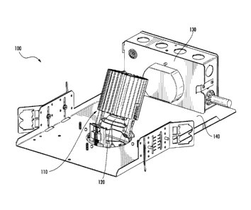
[30] Turning to FIG. 1, an embodiment of a luminaire 100 is depicted. In
particular, FIG. 1
depicts a luminaire 100 having an aiming system 110, with a light source 120,
a junction
box 130, and a support panel 140. In one implementation, the aiming system 110
of
luminaire 100 comprises one or more mechanisms for adjusting a tilt angle
and/or a
rotation angle of light source 120, wherein said mechanisms are described in
further
detail in the figures that follow. In one example, light source 120 may
comprise one or
more light emitting diodes (LEDs). In another example, light source 120 may
comprise
an incandescent light bulb. In yet another example, light source 120 may be
referred to
as a lamp, wherein said lamp may be used to emit electromagnetic radiation in
the visible
spectrum, or outside of the visible spectrum, and using one or more lamp
technologies,
such as, among others, a halogen lamp, a xenon arc lamp, a metal-halide lamp,
a gas-
discharge lamp, a fluorescent lamp, a neon lamp, a mercury-vapor lamp, a
sodium-vapor
lamp, a sulfur lamp, and an electrodeless lamp. Furthermore, as will be
readily apparent
to those of ordinary skill in the art, light source 120 may represent multiple
bulbs/lamps
using a same, or different lamp technologies. Moreover, light source 120 may
output
light in the visible spectrum with any color temperature value. Additionally,
light source
120 may be associated with a power consumption rating ranging from a fraction
of a
Watt (in one example, 0.1 W or below) to several kilowatts and above. Light
source 120
may further comprise one or more lenses and/or filters for focusing and/or
adjusting the
light output intensity/color/pattern, and the like, as further described with
reference to
FIGS. 13-15. For example, in another implementation light source 120 may
further
comprise an electronic circuit having one or more light-emitting elements, an
optic
structure (otherwise referred to as a reflector, or a reflector dome), and/or
a filter
(otherwise referred to as a diffusing filter, and/or a lens), among others.
Such elements
are described in relation to FIGS. 13-15.
[31] In one example, electrical wiring to luminaire 100 may be routed through
junction box
130. Accordingly, junction box 130 may be similar to a conventional junction
box that is
- 6 -
CA 02889468 2015-04-28
=
readily known to those of ordinary skill in the art. For example, junction box
130 may
have one or more internal features (not shown) for routing and/or connecting
one or more
wires and/or cables from one or more power supplies, and the like. In another
example,
light source 120 may operate using a standard household outlet voltage, which,
in one
example, may be 110-120 V at 60 Hz A.C. or 230-240 V at 50 Hz A.C., among
others.
In yet another example, light source 120 may operate using a D.C. voltage, or
an A.C.
voltage outside of a range of outlet voltages. As such, in one implementation,
junction
box 130 may comprise a transformer and/or a power supply device for stepping
up/stepping down an input voltage and/or conditioning an alternating current
(A.C.) input
voltage to be a direct current (D.C.) voltage for supply to light source 120,
and the like.
[321 Luminaire 100 may have a support panel 140 for supporting aiming system
110. In one
configuration, support panel 140 may be constructed from any material with a
strength
capable of supporting aiming system 110, and including, among others, a metal,
an alloy,
a polymer, or a fiber-reinforced material, or a wood, or combinations thereof.
In one
specific example, support panel 140 may comprise a stamped aluminum
sheet/steel sheet,
and the like. In one implementation, support panel 140 comprises an opening,
for
receiving the aiming system 110 such that the aiming system 110 can be
recessed into
(above) support panel 140, and light from light source 120 can be emitted out
through
said opening.
[33] Looking to FIG. 2, a side view of luminaire 100 is depicted. FIG. 2
further depicts
support panel 140 having an upper surface 220 and a lower surface 230. In one
configuration, supports panel 140 may be mounted into a ceiling structure such
that a
lower surface 230 is substantially flush with a ceiling surface, and the like.
In another
example, lower surface 230 is configured to receive one or more ceiling
components. As
such, exemplary ceiling components depicted in FIG. 2 as components 240 and
242,
wherein said exemplary ceiling components may include one or more of, among
others,
- 7 -
CA 02889468 2015-04-28
drywall, ceiling tiles, woodwork, and/or plaster, and the like. In one
configuration, lower
surface 230 comprises one or more elements for receiving a plaster material,
wherein said
one or more elements may comprise dimples, and the like, for encouraging
adhesion
between one or more areas of lower surface 230 and a plaster material. Support
panel
140 further comprises one or more support brackets 210 for coupling support
panel 142
to one or more ceiling structures. Those of ordinary skill in the art will
recognize that
support brackets 210 may comprise one or more apertures, and the like, for
receiving one
or more fasteners, including, but not limited to, screws, bolts, rivets,
nails, staples, tabs,
and the like. Furthermore, a configuration of one or more apertures and/or
coupling-
receiving elements may be of any known
spacing/orientation/combination/pattern,
without departing from the scope of the disclosure described herein.
[34] FIG. 3 depicts a view of the underside of luminaire 100. In particular,
FIG. 3 depicts the
lower surface 230 of support panel 140, and without any ceiling elements. As
will be
apparent, support panel 140 obscures one or more elements of aiming system 110
depicted in FIG. 1 and FIG. 2, and such that light source 120 is primarily
visible through
an aperture 320 in support panel 140. In one configuration, aperture 320 may
be
substantially circular in shape, however any other shape may be utilized,
without
departing from the scope of this disclosure. For example, aperture 320 may be
substantially rectangular in shape, or may comprise an oval shape, and the
like.
Additionally, a trim flange 310 may be visible from the underside of luminaire
100,
wherein trim flange 310 may cover a gap between the structure of luminaire 100
and one
or more ceiling components, such as, drywall, and the like (not shown).
[35] Turning to FIGS. 4-6, which depict luminaire 100 with light source 120 in
differing
orientations. In particular, FIG. 4 depicts luminaire 100 having light source
120 at a first
tilt angle, indicated as tilt angle 450. In one configuration, aiming system
110 comprises
one or more mechanisms for adjusting an angle of light source 120 (tilt angle)
using a tilt
- 8 -
= CA 02889468 2015-04-28
linkage 430. Tilt linkage 430 is described in further detail in FIGS. 11 and
12. In one
example, the tilt angle 450 of light source 120 may be adjusted from an angle
of
approximately 00 to an angle of approximately 60 , and wherein said tilt angle
450may
be defined as an angle between a normal to the surface 220 of support panel
140 (normal
is depicted as line 444), and a centerline 442, among others. Furthermore, and
as will be
apparent to those of ordinary skill in the art, a tilt angle may be defined
with reference to
one or more alternative planes and/or lines, without departing from the scope
of this
disclosure. .
[36] In one example, surface 220 may be substantially horizontal, wherein a
horizontal, or
level, plane may be referenced to a force of gravity. As such, normal 444 may
be
substantially vertical (orthogonal to surface 220). In another example,
surface 220 may
have a normal, such as normal 444, angled with any orientation without
departing from
the scope of this disclosure, wherein said orientation may be referenced to a
force of
gravity or another frame of reference using any coordinate system.
[37] The luminaire 100 may further comprise a heatsink 420, as depicted in
FIG. 4. Heatsink
420 may be configured to dissipate a heat energy output from light source 120
and may
be comprised of, in one example, any material with thermal conductivity
properties
sufficient for transferring an amount of heat energy output of light source
120 and into a
volume of surrounding ambient air, and the like. Accordingly, heatsink 420 may
be
comprised of a metal, or an alloy etc. In one example, heatsink 420 comprises
one or
more fins configured to increase the transfer from light source 120 to ambient
air. In
another example, heat transfer is augmented by one or more fans, thereby
increasing an
effective convective heat transfer coefficient for the illustrative heatsink
420.
[38] In another example, heatsink 420 may comprise a light source holder, such
that the
heatsink 420 is directly coupled to light source 120 by any known coupling
means, such
- 9 -
CA 02889468 2015-04-28
=
as, for example, a screw, a bolt, a rivet, among others. In another example,
heatsink 420
is coupled to light source 120 by one or more thermally conductive materials
and/or
elements, such as, among others, a heat pipe, or a conductive plate or cable.
[39] FIG. 4 depicts aiming system 110 of luminaire 100 having a first tilt
angle 450. In one
example, said first tilt angle 450 may be, approximately 400. FIG. 5 depicts
luminaire
100 with a steeper tilt angle to that depicted in FIG. 4. For example, FIG. 5
depicts
luminaire 100 with a second tilt angle 450 of approximately 20 .
[40] Additionally, FIG. 5 depicts a rotation mechanism 510 of aiming system
110. In one
configuration, rotation mechanism 510 is configured to allow aiming system 110
to rotate
about an axis of rotation (discussed in further detail in relation to FIG. 6).
Accordingly,
in one configuration, said rotation may be in relation to support panel 140,
wherein
rotation mechanism 510 may rotate aiming system 110 in relation to support
panel 140
using rotation spring mechanisms 520a and 520b. In one example, rotation
spring
mechanisms 520a-520b may be leaf springs configured to abut the upper surface
220 of
support panel 140 while having the ability to rotate relative to surface 220,
facilitated by
rotation mechanism 510. In one example, one or more rotation spring mechanisms
520a
and 520b may bear a weight of aiming system 110 on support panel 140, and such
that
rotation spring mechanisms 520a and 520b exert a spring force capable of
bearing the
weight of aiming system 110. In another example, rotation mechanism 510 may
comprise three or more rotation spring mechanisms 520, and the like. In yet
another
example, a cumulative spring force (as a result of a selected one or more
spring constants
of rotation spring mechanisms 520) exerted by one or more rotation spring
mechanisms
520a-520b on the upper surface 220 of support panel 140 may be above a weight
of
aiming system 110, and below a force threshold such that aiming system 110 may
be
removed by a user, from support panel 140, without requiring any specialized
tools (in
- 10-
= CA 02889468 2015-04-28
one embodiment, aiming system 110 may be removed from support panel 140 by
hand,
and the like).
1411 In one example, rotation spring mechanisms 520a and 520b may have an
extended
position such that rotation spring mechanisms 520a and 520b contact the upper
surface
220 of support panel 140, and such that aiming system 110 is rotatably coupled
to support
panel 140. In particular, rotation spring mechanisms 520a and 520b may
contact, and
rotate relative to upper surface 220, while one or more tab structures (not
shown),
extending from rotation mechanism sleeve 740 (as depicted in FIG. 11),
contact, and
rotate relative to lower surface 230 of support panel 140. Accordingly,
rotation spring
mechanisms 520a and 520b may facilitate insert/removal of aiming system 110
from
support panel 140. In particular, rotation spring mechanisms 520a and 520b
may, upon
application of a force exerted by a user in a direction normal to the lower
surface 230 of
support panel 140, compress to allow aiming system 110 to be inserted/removed
from
support panel 140. As such, rotation spring mechanisms 520a and 520b may
facilitate
insertion and/or removal of any system 110 from support panel 140 using a
spring
compression fit, and without using a screw-in coupling, or a keyed coupling,
and the like.
1421 FIG. 6 depicts luminaire 100 with a first rotation angle 610. In one
configuration, aiming
system 110 may rotate relative to support panel 140 about an axis of rotation
612.
Accordingly, in one example, the axis of rotation 612 may be about a
centerline of/axis of
symmetry through aiming system 110. In another example, the axis of rotation
612 may
be different to an axis of symmetry through aiming system 110, and wherein, in
one
example, aiming system 110 is not symmetrical about an axis. In one example,
rotation
angle 610 may be defined as that angle between a first line 620 and a second
line 622,
wherein lines 620 and 622 extend radially from a center point 624, and wherein
said
center point 624 may, in one example, coincide with a geometric center of
aperture 320.
-11-
CA 02889468 2015-04-28
In one example, the rotation angle 610 may be up to 360 degrees, thereby
allowing the
aiming system 110 to rotate around the entire opening in the support panel
140.
[43] FIG. 7 depicts a detailed view of a lower surface 230 of support panel
140. In particular,
FIG. 7 depicts light source 120 coupled to aiming system 110. Furthermore,
aiming
system 110 may comprise a rotation mechanism sleeve 740, otherwise referred to
as an
internal sleeve. Additionally, aiming system 110 is depicted as comprising an
aiming
system internal light shield 730, wherein said internal light shield is
configured for
reflecting an amount of light out from luminaire 100 such that said amount of
light is not
incident on one or more components above the upper surface 220 of support
panel 140.
In another example, the internal light shield 730 is configured to block a
view of one or
more elements of luminaire 100 above upper surface 220 of support panel 140.
Accordingly, internal light shield 730 may obscure a view of one or more
elements, such
as, among others, elements 110 and/or 420, among others, when viewed by an
observer
from below a lower surface 230 of support panel 140. Accordingly, in one
example, light
shield 730 reduces the amount of light "bleeding" into the structure of
luminaire 100
above upper surface 220. In the depicted configuration, rotation mechanism
sleeve 740
comprises a tilt member 710 and a rotation member 720. In one example, tilt
member
710 may comprise an interface configured for actuation of a tilt mechanism,
wherein said
tilt mechanism is described in further detail in relation to FIG. 11.
Accordingly, tilt
member 710 may, in one example, provide a component which may be rotated in
order to
adjust a tilt angle, such as tilt angle 450, of aiming system 110.
Specifically, tilt member
710 may be configured as a screw head and/or a hexagonal cap. Accordingly,
tilt
member 710 may be configured with a Phillips, a slot, a Pozidriv, a square, a
Robertson,
a hex, a hex socket, a security hex socket, a Torx, a security Tonc, a spanner
head, a triple
square, or a poly drive screw drive type, among others. Accordingly, tilt
member 710
may be configured to interface with one or more of a screwdriver, a wrench, a
socket
- 12 -
CA 02889468 2015-04-28
= .
wrench, a hex key/ alien key, or a specialized/proprietary actuation tool,
among others.
In one example, tilt member 710 may be coupled to screw drive 1110 from FIG.
11.
[44] Rotation member 720 may be similar to tilt member 710, and such that
rotation member
720 may be configured for actuation of a rotation mechanism, such as rotation
mechanism 510. In one configuration, rotation member 720 may have a same, or a
different screw drive type as tilt member 710. In one implementation, rotation
member
720 may, in addition to actuating rotation mechanism 510, be configured for
actuation of
a locking mechanism (not shown). Accordingly, upon rotation of rotation member
720
about its own axis, a locking mechanism may prevent rotation mechanism 510
from
rotating about axis of rotation 612. In one example, rotation member 720 may
be
coupled to a threaded member, wherein upon rotation of rotation member 720,
said
threaded member may move into contact with a surface of support panel 142
prevents
rotation of aiming system 110 about said support panel 140, and the like. In
another
example, when said locking mechanism is configured in an unlocked
configuration, tilt
member 710 may additionally/alternatively be utilized to rotate rotation
mechanism
sleeve 740 about rotation axis 612.
[45] FIG. 8 depicts an alternative view of the lower surface 230 of support
panel 140. In
particular, support panel 140 is depicted without aiming system 110 in situ.
As such,
FIG. 8 depicts support panel 140 having a support sleeve 810, a support flange
820, and a
rotation stop 830. In one configuration, support sleeve 810 is configured as a
substantially cylindrical structure extending from the lower surface 230 of
support panel
140. In one configuration, support sleeve 810 is configured to contact
rotation
mechanism sleeve 740, and such that rotation mechanism sleeve 740 may rotate
relative
to support sleeve 810 about a center point of support sleeve 810.
- 13 -
CA 02889468 2015-04-28
[46] Rotation stop 830 may be configured to prevent rotation of aiming system
110 through a
rotation angle, such as rotation angle 610, of, in one example, greater than
370 . In
another example, rotation stop 830 may be configured to prevent rotation of
aiming
system 110 through an angle greater than 365 , 362 , or 360 , among others.
Accordingly, rotation stop 830 may comprise a tab structure projecting from
support
sleeve 810, and configured to contact a corresponding rotation tab 1222
projecting from
rotation mechanism sleeve 740 (as depicted in FIG. 12A).
[47] In one configuration, support flange 820 may be coplanar with lower
surface 230.
Accordingly, in one example, support flange 820 may be positioned between
rotation
mechanism sleeve 740 and rotation mechanism springs 520a and 520b, thereby
rotatably
coupling aiming system 110 to support panel 140. Accordingly, upon insertion
of aiming
system 110 into luminaire 100, one or more rotation mechanism springs 520a-
520b may
be compressed by support flange 820. As aiming system 110 is seated into
position
within luminaire 100, the one or more compressed rotation mechanism springs
520a-520b
decompress/expand into a position on upper surface 220 of support panel 140,
as depicted
in FIG. 5, among others.
[48] FIG. 9 depicts aiming system 110 loosely coupled to a trim assembly 910
by a safety
wire 920. In one example, trim assembly 910trim assembly 910 comprises the
trim
flange 310 from FIG. 3. FIG. 9 depicts aiming system 110 removed from support
panel
140, as will be the case prior to installation of aiming system 110, or during
times of
maintenance and/or replacement of any system 110. Accordingly, when positioned
in
support panel 140, aiming system 110 may be coupled to trim assembly 910trim
assembly 910 by a secondary means. Said secondary means is discussed in
further detail
in relation to FIG. 10. As such, FIG. 9 serves to indicate that aiming system
110 may be
loosely coupled to said trim assembly 910trim assembly 910 by safety wire 920
such that,
in one example, trim assembly 910trim assembly 910 may be removed in order to
access
- 14 -
CA 02889468 2015-04-28
one or more of tilt member 710 and/or rotation member 720, and without
allowing
complete separation of trim assembly 910trim assembly 910 from aiming system
110.
[49] In one example, safety wire 920 may be utilized to orient trim assembly
910 such that
when trim assembly 910 is loosely coupled to aiming system 110, safety wire
920 may be
utilized to maintain a correct orientation/ alignment of trim assembly 910
relative to
aiming system 110.
[50] FIG. 10 depicts an alternative view of trim assembly 910. In particular,
FIG. 10 depicts
trim assembly 910 having the trim flange 310, a trim assembly light shield
1010, and leaf
spring keys 1020a-1020c. In one example, trim assembly 910 may be coupled to
aiming
system 110 using leaf spring keys 1020a-1020c. As such, a leaf spring key
1020a/ 1020b
/1020c may be received into a trim assembly keyway 1140, as depicted in FIG.
11. In
one example, and as previously discussed, a coupling between trim assembly 910
and
aiming system 110 using leaf spring keys 1020a-1020c may be in addition to a
loose
coupling facilitated by safety wire 920. Accordingly, in one example, safety
wire 920
may be utilized to orient trim assembly 910 relative to aiming system 110 such
that a
correct positioning of leaf spring keys 1020a-1020c is maintained relative to
trim
assembly keyway 1140. Accordingly, in one example, trim assembly 910 may be
rigidly
coupled to aiming system 110 using leaf spring keys 1020a-1020c such that the
rigid
coupling is keyed (e.g. a "snap-fit"), and without using a screw-in fit.
[51] In one configuration, trim assembly light shield 1010 reflects an amount
of light out from
luminaire 100. In another configuration, trim assembly light shield 1010
prevents an
amount of light from being projected into an area above the upper surface 220
of support
panel 140.
[52] FIG. 11 depicts a detailed view of tilt linkage 430. In
particular, tilt linkage 430
comprises rotation mechanism sleeve 740 coupled to a support bracket 1150, the
support
- 15-
CA 02889468 2015-04-28
bracket 1150 supporting a linear actuator mechanism 1160. Further, the linear
actuator
mechanism 1160 may comprise a carrier structure 1170, a screw drive 1110, nut
1120,
and coil spring 1130. Also depicted FIG. 11 is a trim assembly keyway 1140a,
as
described in relation to FIG. 10, and configured to receive a leaf spring key
1020 of trim
assembly 910. Additionally, FIG. 11 depicts rotation mechanism springs 520a-
520b, as
described in relation to FIG. 5, and configured for rotatably coupling aiming
system 110
to support panel 140. It is noted that while two rotation mechanism springs
520a-520b
are depicted in FIG. 11, other embodiments may be envisaged as having more
than two
rotation mechanism springs 520, or a single rotation mechanism spring 520.
Also
depicted in FIG. 11 is light shield 730, wherein light shield 730 is coupled
to the linear
actuator mechanism 1160, as described in further detail below.
[53] In one embodiment, one or more components of tilt linkage 430 may be
constructed from
aluminum and/or steel. However, those of ordinary skill in the art will
recognize that one
or more components of tilt linkage 430 may, additionally or alternatively, be
constructed
from, among others, a metal other than aluminum, an alloy other than steel, a
polymer, a
fiber reinforced material, or a wood, or combinations thereof. Furthermore, a
coupling
between two or more components of tilt linkage 430 may comprise one or more of
a
screw, a rivet, a pin, a weld, a braze, a staple, a bolt, a nail, an
interference fit, a key and
keyway coupling, a threaded coupling, or any other means of joining two or
more
components known to those of ordinary skill in the art.
[54] In one configuration, rotation mechanism sleeve 740 is comprises a
substantially circular
shape. Support bracket 1150 may be rigidly coupled to the rotation mechanism
sleeve
740 as depicted, wherein support bracket 1150 comprises a substantially
rectangular
shape, having a first leg coupled to the rotation mechanism sleeve 740 at
coupling point
1180, and a second leg coupled to the rotation mechanism sleeve 740 at
coupling point
1182. In one example, support bracket 1150 may be coupled to a screw drive
1110, such
- 16 -
CA 02889468 2015-04-28
=
that screw drive 1110 is free to rotate in response to actuation of rotation
member 720, as
described in FIG. 7. In one example, carrier structure 1170 is coupled to
screw drive
1110 by nut 1120 such that, upon actuation of screw drive 1110, nut 1120
converts
rotational motion of said screw drive 1110 into linear motion of carrier
structure 1170
along a length of screw drive 1110. In one example, screw drive 1110 has a
spring 1130,
which may be a coil spring, positioned around screw drive 1110, and such that
a first end
of spring 1130 abuts rotation mechanism sleeve 740, as depicted. Additionally,
a second
end of spring 1130 may contact a surface of nut 1120 such that, upon actuation
of linear
actuator mechanism 1160, spring 1130 may be compressed. Specifically, bringing
carrier
structure 1170 towards rotation mechanism sleeve 740 in a downward direction,
wherein
said downward direction as indicated by arrow 1192, nut 1120 may contact, and
compress, spring 1130. As such, a spring force exerted by spring 1130 on nut
1120 may
counterbalance a weight of aiming system 110. This counterbalancing (partial
or wholly
counterbalancing) of a spring force, from spring 1130, with a weight of aiming
system
110 may allow linear actuator mechanism 1160 to be actuated using a lower
manual
rotation force to actuate rotation member 720 in order to translate carrier
structure 1170
in an upward direction, as indicated by arrow 1190.
[55] In one example, tilt linkage 430 may be utilized as an anti-backlash
system, wherein a
spring force exerted by spring 1130 on rotation mechanism sleeve 740 and nut
1120 may
be utilized to ensure that actuation of screw drive 1110 results in linear
translation of
carrier structure 1170 without/ with a reduced amount of backlash. In other
words, a
spring force exerted as a result of compression of spring 1130 between nut
1120 and
rotation mechanism sleeve 740 may allow for, upon actuation of tilt member 710
from
FIG 7, a reduced amount of backlash/ no backlash before said actuation of
member 710 is
converted into linear motion of carrier structure 1170.
- 17 -
CA 02889468 2015-04-28
[56] Conversion of said linear motion of carrier structure 1170 into a
rotational motion of
aiming system 110 is described in further detail in relation to FIGS. 12A-12C.
It is noted
that those directions indicated by arrows 1190 and 1192 may be co-linear, and
may be
parallel to a normal 444, as depicted in FIG. 4. It is also noted that the
terms "upward"
and "downward" used in relation to arrows 1190 and 1192, respectively, are
merely one
example of an orientation of tilt linkage 430. In another example, arrows 1190
and 1192
may be oriented in downward and upward directions, respectively. In yet
another
example, arrows 1190 and 1192 may be oriented in any orientation, and using
any frame
of reference and coordinate system, and the like.
[57] FIG. 12A depicts an alternate view of tilt linkage 430 from that depicted
FIG. 11. In one
configuration, and as shown in FIG. 12A, tilt linkage 430 comprises rotation
mechanism
sleeve 740 coupled to linear actuator mechanism 1160, and having further
couplings to a
light shield bracket 1240 and light source support structure 1250. In one
example, as
depicted in FIG. 12A, light shield bracket 1240 comprises a substantially
semicircular
armature configured to substantially conform to a circular shape of a light
source 120.
Light shield bracket 1240 is coupled to the carrier structure 1170 at pivot
point 1210, and
such that said coupling allows light shield bracket 1240 to pivot relative to
the carrier
structure 1170 as carrier structure 1170 translates in a linear direction
along screw drive
1110.
[58] Rotation mechanism sleeve 714 may be coupled to a light source support
structure 1250
at a pivot point 1220, wherein pivot point 1220 is positioned at first end of
the light
source support structure 1250, and the like. In one example, light source
support
structure 1250 comprises a frame structure configured to support a light
source 120, and
such that light source 120 is rigidly coupled to light source support
structure 1250. As
such, an adjustment of a rotation angle and/or a tilt angle of light source
120 may be
achieved by rotating and/or tilting light source support structure 1250.
Additionally, light
- 18-
CA 02889468 2015-04-28
= .
source support structure 1250 may be coupled to one or more heatsinks, such as
heatsink
420 depicted in FIG. 4. As such, light source support structure 1250 may be
coupled to
light source 120 and and/or heatsink 420 at a second end 1260. In one
configuration,
light shield bracket 1240 is rotatably coupled to light source support
structure 1250 at
pivot point 1230, wherein pivot point 1230 is located between the first end
(indicated by
pivot point 1220) and the second end (indicated by element 1260) of light
source support
structure 1250. Furthermore, in one configuration, the coupling of light
shield bracket
1240 to light source support structure 1250 at pivot point 1230, in
combination with the
coupling of light source support structure 1250 to rotation mechanism sleeve
740 at pivot
point 1220 may be repeated (mirrored) on an opposite side of rotation
mechanism sleeve
740 that is diametrically opposed to pivot point 1220.
[59] In one example, a rotation tab 1222 projects from rotation mechanism
sleeve 740,
wherein rotation tab 1222 is coupled to rotation sleeve 740 by fastener 1224.
Accordingly, as will be readily apparent to those of ordinary skill in the
art, fastener 1224
may comprise any known fastening means such as, among others, a screw, a
rivet, a bolt,
a nail, a pin, among many others. In one example, rotation tab 1222 is
configured to
contact rotation stop 830 of support sleeve 810, and such that aiming system
110 may be
constrained to rotation through an angle of 370 or less. In another example,
rotation
may be constrained to an angle of 365 , 362 , or 360 or less. In one example,
rotation
tab 1222 may be pivoted such that tab 1222 does not project from rotation
sleeve 740,
and such that rotation of aiming system 110 relative to support sleeve 810 and
a rotation
stop 830 is not constrained to, in one example, an angle of 370 or less.
[60]
In one configuration, a coupling of light shield bracket 1240 to carrier
structure 1170 at
pivot point 1210, in addition to a coupling of light shield bracket 1240 to
light source
support structure 1250 at pivot point 1230, allows a linear motion of carrier
structure
1170 to be converted into a rotational motion of light source support
structure 1250, and
- 19 -
CA 02889468 2015-04-28
consequently, light source 120. Described in further detail, actuation of
rotation member
720 may actuate screw drive 1110, thereby linearly translating carrier
structure 1170 in
an upward direction, indicated by arrow 1190. This linear motion of carrier
structure
1170 is translated into a rotational motion of light shield bracket 1240
through pivot point
1210. Rotational motion of light shield bracket 1240 is accompanied by motion
of pivot
point 1210 of light shield bracket 1240 in an upward direction, wherein said
upward
direction is indicated by arrow 1190. As pivot point 1210 of light shield
bracket 1240 is
moved in an upward direction, pivot point 1230 of light shield bracket 1240
moves
towards support bracket 1150. Conversely, as carrier structure 1170 moves in a
downward direction, indicated by arrow 1192, pivot point 1230 moves away from
support bracket 1150. As such, a motion of pivot point 1230 towards/away from
support
bracket 1150 gives rise to a leverage that may rotate light source support
structure 1250
about pivot point 1220. Successive steps in a motion of light source support
structure
1250 are depicted in FIG. 12A-12C. Accordingly, FIG. 12A depicts light source
support
structure 1250 at a first tilt angle, wherein said first tilt angle may be
approximately 30 ,
and wherein the first tilt angle is referenced relative to a normal (e.g.
normal 444) to an
upper surface 220 of support panel 140, similar to tilt angle 450 from FIG. 4.
In this
example of FIG. 12A, carrier structure 1170 is positioned at a lower end of
screw drive
1110, thereby setting up a steep/high tilt angle of light source support
structure 1250.
Turning to FIG. 12B, carrier structure 1170 is depicted as positioned
approximately
midway along screw drive 1110. As such, as carrier structure 1170 is
translated in an
upward direction (direction 1190), this linear motion gives rise to rotational
motion of
light source support structure 1250 into a more upright position, and having a
shallower
tilt angle. In one example, the tilt angle depicted in FIG. 12B may be
approximately 15 .
It will be noted that during translation of carrier structure 1170 along screw
drive 1110 in
the upward direction 1190, spring 1130 may exert a spring force on a surface
of nut 1120,
thereby counterbalancing a weight (partially or wholly) of aiming system 110.
- 20 -
CA 02889468 2015-04-28
[61] In one example, safety wire 920 may be retracted into rotation mechanism
sleeve 720, as
depicted in FIG. 12A-12C. This retracted position of safety wire 920
corresponds to a
configuration coupling cartridge 910 to rotation mechanism sleeve 920, as
previously
described.
[62] Returning to FIG. 12C, carrier structure 1170 is depicted in a
position at a substantially
upper end of screw drive 1110, wherein screw 1130 is in a fully decompressed
position,
and light source support structure 1250 has been pulled into an upright
position by light
shield bracket 1240. In one example, light source support structure 1250, and
as such,
light source 120, have a tilt angle of approximately 00 in FIG. 12C.
[63] FIG. 12A-C further depicts aiming system internal light shield 730
coupled to light shield
bracket 1240, wherein light shield 730 moves as a tilt angle of light source
120 is
adjusted, as depicted in the sequence of FIG. 12A-12C. For example, in FIG.
12A, light
source 120 is depicted as having a high tilt angle, and light shield 730 is
depicted as being
in a lowered position, wherein said lowered position prevents an amount of
light from
escaping into an area of luminaire 100 above the upper surface 220 of support
panel 140.
Moving to FIG. 12B, light source 120 is depicted as having an intermediate
tilt angle, and
light shield 730 is depicted in a partially raised position. Following on to
FIG. 12C, light
shield 730 is depicted in a fully raised position (low tilt angle) as light
source 120 is
depicted in a fully upright position.
[64] It is noted that aiming system 110 may adjust a tilt angle of light
source 120 from an
angle of approximately 00 to an angle of approximately 60 . Furthermore, a
tilt angle of
aiming system 110 may be adjusted by a screw drive 1110, wherein said screw
drive
1110 is configured to allow the tilt angle to be infinitely adjusted (to any
angle) between
a first angle (which may be approximately 0 ) to a second angle (which may be
approximately 60 or more). Furthermore, rotation mechanism 510 may be
configured to
-21 -
CA 02889468 2015-04-28
=
allow a rotation angle of aiming system 110, such as rotation angle 610, to be
infinitely
adjustable between a first angle of rotation, which may be 0 , and a second
angle of
rotation, which may be 370 or more.
[65] FIGS. 13A and 13B depict an assembly of luminaire 100. In particular,
FIG. 13A
heatsink 420 coupled to a first light source support structure 1250 and a
second light
source support structure 1252. Further, an electronic element 1302 may be
coupled to
heatsink 420, wherein electronic element 1302 may comprise one or more light-
emitting
elements. In one specific example, electronic element 1302 may comprise one or
more
LED circuits. Those of ordinary skill in the art will understand that
electronic element
1302 may comprise any known light source including, among others, an
incandescent
bulb or a halogen lamp, among others. As such, electronic element 1302 may be
rigidly
coupled to heatsink 420 such that heat energy may be conducted between element
1302
and heatsink 420.
[66] In one example, assembly 1300 comprises an optic cartridge 1307 removably
coupled to
the first light source support structure 1250 and the second light source
support structure
1252. In particular, optic cartridge 1307 may comprise an optic cartridge
sleeve 1308, a
first optic cartridge arm 1310, and a second optic cartridge arm 1312, and
wherein optic
cartridge 1307 may be removably coupled to elements 1250 and 1252 by sliding
the first
optic cartridge arm 1310 into a first support structure keyway 1322 and the
second optic
cartridge arm 1312 into a second support structure keyway 1324. Accordingly,
in one
example, optic cartridge 1307 may be removably coupled to elements 1250 and
1252 by
sliding in/out along a direction indicated by arrow 1320, and the like.
[67] In one example, assembly 1300 comprises light source 120, wherein light
source 120
further comprises electronic element 1302, optic 1304 (otherwise referred to
as optic
reflector, or reflector), and/or diffusing filter 1306 (otherwise referred to
as a lens).
- 22 -
CA 02889468 2015-04-28
[68] FIG. 13B depicts an alternative view of assembly 1300. In one example,
FIG. 13B
depicts optic cartridge 1307 removably coupled to the first light source
support structure
1250. Accordingly, light source support structure 1250 further comprises a
leaf spring
1330, the fastener 1332, a fastener hole 1334, and a fastener slot 1336. In
one example,
fastener 1332 may comprise any fastening means known to those ordinary skill
in the art,
including, among others, a screw, rivet, a pin, or a tab, among others. In one
example,
fastener 1332 may be utilized to rigidly coupled the first light source
support structure
1250 to heatsink 420. Accordingly, in one example, fastener 1332 may be
removed, and
the first light source support structure 1250 may be adjusted such that
fastener 1332 is
received into fastener hole 1334 or fastener slot 1336. In this way, by
adjusting the first
light source support structure 1250, a distance between diffusing filter 1306
and
electronic element 1302 may be adjusted to accommodate varying light source
types,
and/or varying optic (1304) shapes and/or sizes. Accordingly, it will be
readily
understood to those of ordinary skill in the art class a similar configuration
of a fastener,
such as fastener 1332, and elements 1334 and 1336 may be present on the second
light
source support structure 1252, and the like.
[69] In one example, leaf spring 1330 may be utilized to removably couple
optic cartridge
1307 (and in particular, optic 1304) to electronic element 1302. Accordingly,
leaf spring
1330 may engage with the second optic cartridge arm 1312 to urge said arm
towards
electronic element 1302 using a spring force. It will be readily understood to
those of
ordinary skill in the art that the second light source support structure 1252
may comprise
a similar leaf spring to leaf spring 1330 (not shown).
[70] FIGS. 14A and 14B depict a luminaire 100 assembly. In particular, FIG.
14A depicts one
view of an assembly 1400 comprising optic cartridge 1307 and optic 1304. In
one
example, assembly 1400 may be configured to be removably coupled to assembly
1300
from FIG. 13. As such, assembly 1400 may be configured to be inserted/removed
from
- 23 -
CA 02889468 2015-04-28
assembly 1300 along that direction indicated by arrow 1320 from FIG. 13A. In
one
example, optic cartridge 1307 comprises a first optic cartridge arm 1310, and
optic
cartridge sleeve 1308, a second optic cartridge arm 1312, and a retention
spring 1326. In
one example, retention spring 1326 may be configured to retain optic 1304
within optic
cartridge 1307 by exerting a spring force on optic 1304 to urge said optic
into contact
with optic cartridge sleeve 1308, and the like.
[71] In one example, as depicted in FIG. 14A, optic 1304 may be removably
coupled to a
diffusing filter 1306. As such, diffusing filter 1306 may comprise any
material
configured to diffuse visible light. Accordingly, diffusing filter 1306 may
comprise a
polymer, a glass, or any other material configured to be partially or wholly
transparent to
visible light. In another embodiment, element 1306 may be referred to as a
lens, and
configured to focus and/or adjust light emitted from electronic element 1302.
[72] In one example, optic 1304 and diffusing filter 1306 may be configured to
be removably
coupled to optic cartridge 1307. Accordingly, optic 1304 and diffusing filter
1306 may
be removed from optic cartridge 1307 by pivoting retention spring 1326 to an
open
position (not shown) from that closed position depicted in FIG. 14A. In one
example,
optic 1304 and diffusing filter 1306 are depicted removed from optic cartridge
1307 in
FIG. 15.
[73] FIGS. 15A and 15B depict an optic assembly 1500. In particular, FIG. 15A
depicts optic
1304 and diffusing filter 1306. In one example, as depicted in FIG. 15B, optic
1304
comprises an opening 1502, wherein opening 1502 may be utilized to allow light
to enter
from electronic element 1302. In one example, optic 1304 may have a reflective
inner
surface (not shown) such that light entering through opening 1502 is reflected
out
through diffusing filter 1306.
- 24 -
CA 02889468 2015-04-28
[74] FIGS. 16A and 16B depict a luminaire assembly configured to adjust a tilt
angle of a
light source from a wall-wash position to a downlight position. In particular,
FIG. 16A
depicts an assembly 1600 comprising the rotation mechanism sleeve 740,
heatsink 420,
light source 120, and second light source support structure 1252. Further,
assembly 1600
comprises an angle adjustment arm 1604 configured to adjust a tilt angle of
light source
120 from a wall-wash position to a downright position, wherein the wall-wash
position is
indicated by label 1606, and the downright position is indicated by label
1608.
Accordingly, in one example, a tilt angle of light source 120 is set by
coupling the second
light source support structure 1252 to the rotation mechanism sleeve 740 with
the angle
adjustment arm 1604. As such, a tilt angle of light source 120 from assembly
1600 may
be adjusted without using a tilt linkage, such as tilt linkage 430.
[75] In one example, angle adjustment arm 1604 is adjusted from a wall-wash
position to a
downright position by actuation of fastener 1602. In one example, fastener
1602 is
configured to be actuated with a screwdriver 1610, however those of ordinary
skill in the
art will understand that fastener 1602 may comprise any known means for
fastening
including, among others, a bolt, a thumb screw, or a rivet, among others. In
one example,
assembly 1600 from FIG. 16A is configured with light source 120 at a wall-wash
angle,
as indicated by wall-wash label 1606 aligning with the second light source
support
structure 1252.
[76] FIG. 168 depicts assembly 1600 being adjusted from a wall-wash position
to a downright
position. In particular, FIG. 16B depicts angle adjustment arm 1604 having a
first tab
1620 and a second tab 1622. Furthermore, the second light source support
structure 1252
is configured with a coupling hole 1624 configured to receive one of the first
tab 1620 or
the second tab 1622. Those ordinary skill in the art will understand that
angle adjustment
arm 1604 may alternatively comprise a single tab, or multiple tabs in excess
of those two
tabs 1620 and 1622 depicted in FIG. 16B, without departing from this
disclosure.
- 25 -
CA 02889468 2015-04-28
1771 In one example, a tilt angle of light source 120 is adjusted from a wall-
wash angle to a
downlight angle by pivoting angle adjustment arm 1604 about fastener 1602 to
remove
the first tab 1620 from the coupling hole 1624 (and as indicated FIG. 16B).
Accordingly,
it will be readily apparent to those of ordinary skill in the art that a wall-
wash angle
(indicated by an alignment of label 1606 with support structure 1252) or a
downlight
angle (indicated by alignment of label 1608 with support structure 1252) may
align light
source 120 at any tilt angle. For example, a wall-wash angle may correspond to
a tilt
angle 450 of approximately 40 -50 . Furthermore, a down light angle may
correspond to
a tilt angle 450 of approximately 5 , or less than 10 , and the like.
1781 FIG. 16C depicts assembly 1600 adjusted to a downlight tilt angle, as
indicated by
alignment of the second tab 1622 with the coupling hole 1624. Accordingly,
upon
receiving the second 1622 into the coupling hole 1624 (as indicated in FIG.
16D),
fastener 1602 may be tightened to lock support structure 1252 into the
depicted
downlight position.
1791 The present invention has been described in terms of preferred and
exemplary
embodiments thereof Numerous other embodiments, modifications and variations
within the scope and spirit of the appended claims will occur to persons of
ordinary skill
in the art from a review of this disclosure.
- 26 -