Note: Descriptions are shown in the official language in which they were submitted.
CA 02889560 2015-04-24
APPARATUS FOR A SHOE
FIELD OF THE INVENTION
[0001] The present invention relates to an apparatus for a shoe. More
specifically, the present
invention relates to an apparatus that is designed to provide safety
properties, as well as for
the removal of foreign particles from the sole of a shoe.
BACKGROUND OF THE INVENTION
[0002] The interaction between footwear and a surface is of utmost important
for individuals
who are looking to maximize performance. As such, individuals often use
footwear designed
to provide a high level of traction between the sole of the shoe and a surface
(i.e. a basketball
court, a badminton court, etc.). However, as the sole of a shoe becomes dirty,
its ability to
stick onto a surface will diminish; thereby decreasing athletic performance
and increasing the
possibility of injury as a result of slippage on a given surface.
[0003] Traction with a surface may be restored to an athletes' footwear by
cleaning the sole
of the shoe by, for example: (i) wiping the sole of the shoe on sticky mats
known as
Stick'UmsTm or Slipp-NottTm, which are placed on the outside boundary of a
playing surface;
(ii) wiping a dry or moist cloth, such as a sock or rag, onto the sole of a
persons shoe; (iii)
applying a powder onto the sole of a shoe; and/or (iv) using a variety of
cleaning pads or other
devices that may attached over the tongue or shoelaces of a shoe.
100041 United States Patent no. 4,823,426 discloses a cleaning device for
dislodging, picking
up and retaining foreign particles, wherein the device is attached onto a shoe
by making use
of attachment means that clasps around the fastened footwear laces and are
interlocked by
means of VelcroTM type fastener strips. Such device is disclosed in FIGURE 1,
of the present
application.
100051 As it can be seen in FIGURE 2, United States Patent no. 5,421,106
discloses a
removable shoestring cover for athletic shoes which provides an upwardly
facing wiping
surface of suede or other material, and which cover is attached to the
shoestrings at the upper
and lower edge of the cover by flaps which fold around portions of the
shoestrings and are
held by a hook and loop type fastener.
100061 United States Patent no. 5,555,564 discloses a shoe sole wiping pad
sewn to the outer
surface of an athletic sock. The wiping pad has a moisture-bearing wiping
surface that
1
CA 02889560 2015-04-24
removes dust and debris from the sole of an athletic shoe. The wiping pad
cannot be removed
from the sock for moisture replenishment.
[0007] United States Patent no. 6,128,801 discloses a shoe sole cleaner that
removes debris
from a sole of a user's shoe by swiping the sole over the shoe sole cleaner on
the user's
opposing shoe. As it can be seen in FIGURE 3, a two-part mechanical fastener
(e.g., hook-
and-loop) securing the shoe sole cleaner to a shoe by its shoelaces.
[0008] Japanese patent application no. JP19990216643 discloses a device
comprising a base
member located on the tip of shoe and cleaner member. As it can be seen in
FIGURE 4, the
two members are detachably fastened to one another.
[0009] As it can be seen in FIGURE 5, Chinese patent application no.
CN20112111155U
discloses a sports shoe with anti-slippage shoe tongues made with magic tape.
1000101 International laid-open publication no. W02012/148496A1 (corresponding
to U.S.
Publication no. 2014/0047652) discloses a traction-enhancing cleaning kit,
comprising a
hook-and-loop attachment, that is mounted atop an anchoring platform. As it
can be seen in
FIGURE 6, the kit must be laced onto an athlete's shoe; thereby requiring an
individual to
remove the laces from the shoe(s) and rethreading them through the device to
attach it
thereon.
[000111An important drawback of the devices of the prior art is that when
pressure is applied
thereon by a user, i.e., when a user wipes the sole of his or shoe over the
device, or when an
athlete makes a sudden movement during play, the attaching means of these
devices detach
themselves from the shoe. For instance, when VelcroTM attachments are used,
FIGURES 1
and 3, they may become loose during play or worse completely detach themselves
from the
corresponding member, as a result of the amount of pressure an athlete applies
onto the
opposite shoe so as to clean the sole of the opposite shoe, or as result of
quick player
movements. Moreover, when VelcroTM is used in shoe devices, it is subject to
wear and tear
and become simply ineffective when fibres and/or dirt particles accumulate
therein; thereby
completely losing its adhesive properties. Velcro." also has an additional
drawback of
abrading shoelaces, as well as other fine materials such as silk, rayon, or
fine cotton blends,
which may be in users gym bag.
[00012] In other instances, the device of the prior art, FIGURE 6, cannot be
easily attached
onto a shoe. In this particular case, an individual must remove the laces of a
shoe, mount the
device on the tongue of a shoe and begin threading the laces through the
stirrups of the device
2
CA 02889560 2015-04-24
and the corresponding eyelets of a shoe. Not only is this a time consuming
process, but, as a
result of the construction or design of the device, the stirrups of the device
are susceptible of
breaking or being damaged, as a result of: (i) normal wear and tear of the
device, and (ii) the
over tightening of shoelaces by an individual; thereby exerting too much
pressure on the
stirrups, which in turn causes them to break. In the same vein, the stirrups
of the device may
be damaged as a result of the athlete's brusque rubbing of his or her shoe on
the opposite
shoe.
[00013] There is therefore a need for a safe, compact, portable and universal
apparatus that
can be easily attached onto and detached from a shoe and that can perform a
multitude of
functions, such as, for example: (i) providing anti-slip properties to a sole
of shoe; thereby
enhancing an individual's traction on a surface (i.e., a playing or performing
surface); (ii)
provide one or more pocket(s), in which an individual can store assets (i.e.,
valuables); as well
as (iii) providing reflective and/or emitting lighting properties in low-light
conditions.
SUMMARY OF 'I'11E INVENTION
[00014] The present invention overcomes all of the above drawbacks by
providing an
apparatus capable of, for example: firstly, preventing one from slipping when
playing sports
on a dusty or dirty surface; secondly, allowing one to secure one's small
personal effects on to
their person when playing sports, or pursuing recreational activities, which
is safer than using
a locker for example; and/or thirdly, optimizing one being seen in low-light
conditions, i.e. at
night when walking, jogging, or cycling outside.
[00015] In accordance with one aspect of the invention is to provide an
apparatus removably
attachable to a shoe with laces and a sole, wherein the apparatus comprises:
- a front side and back side, lower and upper opposite ends and opposite
sides;
- the front side of the apparatus comprising a front pocket;
- the back side of the apparatus comprising a transversal strap extending
between both
opposite sides of the apparatus and a longitudinal strap extending from the
lower opposite end
of the apparatus, said longitudinal strap comprising an extendible loop
configured to be
removably latched onto a hook device located at the upper opposite end of the
apparatus;
wherein when removably attaching the apparatus onto the shoe, the longitudinal
strap
is weaved through the laces of the shoe and the extendible loop is extended
over the hook
device so as to securely attach the apparatus onto the shoe.
100016] According to another aspect of the invention, the apparatus further
comprises a
luminescent material for reflecting and/or emitting light.
3
CA 02889560 2015-04-24
[00017] According to another aspect of the invention, the apparatus further
comprises a flap
for closing the pocket.
[00018] According to another aspect of the invention, the apparatus further
comprises a
pocket for receiving assets therein.
1000191According to yet another aspect of the invention the apparatus further
comprises a
light emitting diode adapted to be inserted into the front pocket.
[00020] Generally, the object of the invention is to provide an apparatus
which can be readily
and removably attached to the outer portion of an athlete's shoe (i.e., above
the tongue of the
shoe) to enable the quick removal of foreign particles from the soles of the
shoe by simply
brushing the soles of the shoe worn on each foot back and forth across the
cleaning device on
the shoe worn on the other foot, whilst releasing an amount of liquid
solution. The
combination of materials used for the apparatus according to the present
invention have been
selected to avoid loss of liquid solution during use of thereof.
BRIEF DESCRIPTION OF 'THE DRAWINGS
1000211The foregoing objects, and others, will in part be obvious and in part
pointed out
more fully hereinafter in conjunction with the written description of a
preferred embodiment
of the invention illustrated in the accompanying drawings in which:
1000221 FIGURE 1 is a perspective view of a cleaning device of the prior art,
in open and
closed positions, for dislodging, picking up and retaining foreign particles
of shoe, as
disclosed in U.S. Patent no. 4,823,426.
[00023] FIGURE 2 is a cross-section view of a removable shoestring cover
according to the
prior art, as disclosed in United States Patent no. 5,421,106.
[00024] FIGURE 3 is a perspective and exploded view of a shoe sole cleaner of
the prior art,
as disclosed in United States Patent no. 6,128,801.
1000251 FIGURE 4 is a perspective and exploded view of a device of the prior
art for cleaning
the sole of a shoe, as disclosed in Japanese patent application no.
JP19990216643.
4
CA 02889560 2015-04-24
100026] FIGURE 5 is a side view of an anti-slippage device of the prior art,
as disclosed in
Chinese patent application no. CN20112111155U.
1000271 FIGURE 6 is a perspective view of a traction-enhancing cleaning kit of
the prior art,
as disclosed in U.S. Publication no. 2014/0047652.
1000281 FIGURE 7 is a front view of an apparatus according to a preferred
embodiment of the
present invention.
[00029] FIGURE 8 is a perspective view of a liquid releasing device according
to a preferred
embodiment of the present invention.
1000301 FIGURE 9 is a perspective view of the back side of the apparatus shown
in FIGURE
7.
1000311FIGURE 10 is another perspective of the back side of the apparatus
shown in
FIGURE 7.
[00032] FIGURE 11 is a perspective view of back side of the apparatus shown in
FIGURE 7.
1000331 FIGURE 12 is a perspective view of the apparatus shown in FIGURE 7,
attached to
the shoe laces of a shoe.
1000341 FIGURE 13 is a perspective view of the apparatus shown in FIGURE 7,
attached to
the shoe laces of a shoe.
[00035] Figure 14 is a perspective view of a permeable bladder according to a
preferred
embodiment of the present invention.
1000361 While the above identified drawings set forth several preferred
embodiments, other
embodiments of the present invention are also contemplated, as noted in the
detailed
description. This disclosure presents illustrative embodiments of the present
invention by way
of representation and not limitations. Numerous other modifications and
embodiments can be
devised by those skilled in the art which fall within the scope and spirit of
the principles of
this invention.
DETAILED DESCRIPTION OF THE INVENTION
CA 02889560 2016-10-27
[00037] Reference will now be made in detail to preferred embodiments of the
present
invention, examples of which are illustrated in the accompanying drawings.
Wherever
possible, the same reference numbers will be used throughout the drawings to
refer to the
same or like parts.
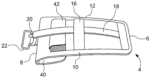
[00038] As it can be seen in FIGURES 12, 13 and 14, the present invention is
an apparatus 1
removably attachable to a shoe 50 with laces 52 and a sole 54. As it appears
in FIGURES 7,
9 and 10 to 13, the apparatus 1 comprises a front side 2 and back side 4,
lower and upper
opposite ends 6, 8 and opposite sides 10, 12. The front side 2 of the
apparatus 1 comprises of
a front pocket 14.
[00039]FIGURES 7 and 13 are perspective views of the front side 2 of the
apparatus 1. As it
can be seen therein, the front pocket 14 may comprise of a front porous side
24 or a
luminescent material for reflecting and/or emitting light. In a preferred
embodiment, the front
porous side 24 is made of up a material, such as mesh, that allows for the
release (or passing
through), preferably a metered release, of a liquid solution contained within
the liquid
releasing device 26 onto the sole 54 of a shoe 50 when pressure is applied
thereon by an
individual other shoe. Different types of porous materials can be considered,
for example:
mesh, frames or matrices manufactured out of polymers, plastic, metals or
combinations
thereof, as well as other types of porous materials known to a person skilled
in the art.
Preferably, a factor to consider when selecting the porous material is that
the pores of the
material cannot be so large that the liquid solution freely flows from, or
drips out of the liquid
releasing device 26 onto the individual's shoe, especially when pressure is
applied onto the
front pocket 14 by the individual's other shoe. Additionally, the use of a
front porous side 24
allows for the collection of dirt or dust particles. Indeed, when pressure is
applied onto the
front pocket 14 with the individual's other shoe a sufficient amount of liquid
is released from
the liquid releasing device 26 so as to enable the sole 54 of the other shoe
50 to regain its anti-
slip properties and be cleansed. In other words, when the liquid releasing
device 26 is inside
the front pocket 14 and upon pressure being applied thereto by another shoe, a
liquid solution
inside the liquid releasing device 26 is released through the front porous
side 24 so as to clean
the sole of the other shoe.
[00040] In a preferred embodiment, the opposite sides 10, 12 and the opposite
ends 6, 8 can
be equipped with brush-like, bristled edges, so as to remove dust or dirt from
the bottom of a
shoe. Alternatively, the opposite sides 10, 12 and opposite ends 6, 8 can be
equipped with
squeegee type materials, which could be used to absorb excess liquid from the
sole 54 of the
shoe 50.
6
CA 02889560 2016-10-27
[00041] As it can be seen in FIGURES 7 and 8, the front pocket 14 is further
adapted to
receive a liquid releasing device 26, which can be easily washed, dried,
reused, recycled
and/or replaced. FIGURE 8 is a perspective view of the liquid releasing device
26. In a
preferred embodiment, the liquid releasing device 26 comprises a permeable
bladder 28
(shown in FIGURE 14) capable of retaining a liquid solution and an external
surface made up
of filaments 30. The permeable bladder 28 can be reusable or not. In a
preferred embodiment
the permeable bladder is made up of sponge like filaments 30 and can possibly
contain an
inlet for receiving a liquid solution. In a preferred embodiment, the liquid
releasing device 26
can be doused, or soaked, with a variety of liquids, which are retained
therein. As for choice
of liquid solution to be used in the liquid releasing device 26, different
liquid solutions can be
considered by a person skilled in the art. For example, one could make use of
water, soap
and/or tackifier solutions, gels, antimicrobial solutions, either alone or in
combination thereof;
in as long as the liquid solution does not damage the playing surface or the
soles of a shoe.
[00042]In a preferred embodiment, and as it appears in FIGURE 14, the
permeable bladder
28 comprises a sponge like material, i.e., sponge 32, and a support rod 34
that extends from
one end 36 of the permeable bladder 28 to the other 36'. The support rod 34
can be used to
provide the permeable bladder 28 a structure. The support rod 34 can be made
out of plastic
or any other material as contemplated by a person skilled in the art. In a
preferred
embodiment, the support rod 34 is designed in such a way to have at least one
enlarged
portion so as to reduce compression of the sponge 32 when pressure is applied
thereon by the
individual's shoe and to avoid leakage. The at least one enlarged portion 38
can be in the form
of one or more bump(s) or elongated arm(s); the latter of which is
perpendicular to the
support rod 34. Of course, other designs may be contemplated by a person
skilled in the art, in
as long as an individual cannot completely compress (or exert too much
pressure on) the
liquid releasing device 26 so that the liquid solution contained therein
gushes out. The use of
at least one enlarged portion 38, in conjunction with a sponge 32, preferably
allows for
improved surface contact between the liquid releasing device 26 and the front
porous side 24.
This design allows the sponge 32 and filaments 30 to be raised towards the
front porous side
24 and have a greater surface contact with the sole 54 of the shoe 50 being
rubbed over the
apparatus 1. Such preferably enables an individual to clean a greater surface
area of the sole
54 of the other shoe 50 with the apparatus 1 according to the present
invention, and restoring
the shoe(s) 50 properties, such as adhesion, tackiness and the like to a
playing surface;
thereby avoiding slippage and player injury.
7
CA 02889560 2016-10-27
[00043] As opposed to inserting a liquid releasing device 26 in the front
pocket 14, it is
possible to insert a light emitting diode ("LED") therein. By doing so,
individuals can be seen
at dawn, dusk, or night, and in all weather conditions. Preferably, an
individual could insert a
flexible LED light strip or glow stick the front pocket 14 of the apparatus 1.
As a result of the
properties of the front pocket, namely the front porous side 24 and the use of
a porous
material (i.e., mesh), it the light emitted from the LED radiates and reflects
on the mesh
therefore providing more surface radiance.
[00044] As opposed to having a front porous side 24, the front pocket 14 can
be made of a
luminescent material for reflecting and/or emitting light. In cases where a
light source, for
example a headlight or streetlight, shines onto the luminescent material, the
front pocket 14
will reflect and/or emit such light; thereby, allowing a driver of a vehicle
or a passer-by to see
where the individual is exercising. This embodiment is particularly
advantageous when an
individual is exercising at dusk or at night, and needs to be visible to
others for safety
concerns. In a preferred embodiment, luminescent materials include but are not
limited to
materials such 3MScotchliteTm and other reflective materials known to a person
skilled in the
art.
[00045] As it appears in FIGURES 9 to 11, the back side 4 of the apparatus 1
comprises a
transversal strap 16 extending between both opposite sides 10, 12 of the
apparatus 1 and a
longitudinal strap 18 extending from the lower opposite end 18 of the
apparatus 1. The
longitudinal strap 18 comprises an extendible loop 20, which is configured to
be removably
latched onto a hook device 22 located at the upper opposite end 8 of the
apparatus 1. In a
preferred embodiment, the hook device 22 may be a T-shaped handle, whereupon
the
extendible loop 20 can be looped thereover. Of course, other means for
fastening the
extendible loop 20 over the hook device 22 can be considered; for example:
VelcroTM
attachments, snap buttons, hitching posts and the like.
[00046] In order to attach the apparatus 1 onto the shoe 50, the longitudinal
strap 18 is weaved
through the laces 52 of the shoe 50 and the extendible loop 20 is extended
over the hook
device 22 so as to securely attach the apparatus onto the shoe. As it appears
in FIGURES 12
and 13, the longitudinal strap 18 is also adapted to be woven under the
transversal strap 16 of
the apparatus 1 so as to provide a further point of contact between the shoe
and the apparatus
for reducing movement of the apparatus thereon. Preferably, the longitudinal
strap 18 is made
out of semi-flexible fabric so that the apparatus 1 is in closer contact with
the laces 52 of a
shoe 50. In order to attach the apparatus 1 onto the shoe 50, an individual
places the apparatus
1 over the shoe 50, and then: (a) weaves the longitudinal strap 18 under the
laces, (b) over the
8
CA 02889560 2016-10-27
transversal strap 16 (i.e., closest to back side 4 of the apparatus 1), (c)
under the shoelaces 52,
and then (d) extends the extendible loop 20 over the hooking device 22. Once
such has been
completed, the apparatus 1 is securely attached onto the shoe 50. The same can
be done for
the individual's alternate shoe 50. An advantage of using such an apparatus 1
is that: (I)
liquid solution can easily be added onto the liquid releasing device 26, which
can absorb the
liquid as a result of the sponge 32, and (2) it can easily be removed from the
shoe 50 and
cleaned, without undoing the laces 52 of the shoe 50, as disclosed in the
prior art.
[00047] To remove the apparatus 1, one only need to lift (or unhook) the
extendible loop 20
from the hook device 22. Once the extendible loop 20 has been freed from of
the hook device
22, the individual can simply pull the apparatus 1 from the shoe 50 and the
longitudinal strap
18 will naturally unthread itself from the shoelaces, as the apparatus is
being pulled off the
shoe 50.
[00048] According to the present invention, the back side 4 of the apparatus 1
can also be
equipped with a back pocket 42 for receiving assets, such as keys, cards,
jewellery, money
and other small valuables, therein. The front pocket 14 can serve the same
function when no
liquid releasing device 26 or light emitting diode is inserted therein. As for
the front pocket
14, the back pocket 42 is preferably stitched or integrated onto the apparatus
1. The addition
of a back pocket 40 to 42 to the apparatus 1 allows an individual to be free
of additional
apparel, such as bracelets or necklaces on which they would normally attach
their locker keys
or other valuables, during exercise or play.
[000491As it can be seen in FIGURES 7, and 9 to 13, the apparatus 1 according
to the present
invention, further comprising a flap 40 for closing the pocket. Indeed, a flap
40 can be
positioned on both the front side 2 and/or the back side 4 of the apparatus.
When the flap 40 is
located on the front side 2, it can be used to cover the laces 52 of a shoe
50, as well as a
portion of the front pocket 14 so as to ensure that the assets, the LED or the
liquid releasing
device 26 contained therein are secured and protected from the elements (i.e.,
rain water). In a
preferred embodiment, the flap 40 is preferably made of a water-resistant
material. The flap
40 can be securely attached onto the apparatus by making use of VelcroTM, a
snap or other
fastening means known to a person skilled in the art; thereby making it easy
to open and close
the flap. By adding a flap 40 to the apparatus 1, it allows for a watertight
seal between the
outside elements and the contents of the front and back pockets 14, 42. By way
of the
aforementioned design, the assets contained with the front and back pockets
14, 42 do not get
wet.
9
CA 02889560 2015-04-24
[00050] In addition to the above, the kit according to the present invention
can be equipped
with a strap. The strap can preferably be located across the middle back of
the kit. Indeed, the
strap could be threaded through the shoelaces and once the shoe laces have
been pulled and
tied by an athlete, it would prevent the kit according to the present
invention from flopping up
and down when worn.
[00051] In another embodiment, the apparatus according to the present
invention could further
comprise such a shoelace locking mechanism, which prevents one's shoelaces
from becoming
undone.
1000521 In use, it is preferred to install the apparatus 1 on both shoes. When
an individual has
completed his or her exercise or play, the individual can easily remove the
apparatus 1 from
his or her shoes, and insert them into a carrying case.
[00053] Furthermore, and by way of the design of the apparatus according to
the present
invention, the apparatus is easily removably attachable to a shoe. Indeed, the
apparatus
should be easy to put on and remove. Many athletes use their outdoor shoes as
indoor shoes
and will not want to have to unlace their shoes to lace in an anti-slip
device, or do the reverse
to remove it.
[000541 It should now be apparent that the above-described invention provides
an effective
apparatus for: (i) cleaning the soles of athletes' shoes, (ii) storing assets
therein, as well as for
(iii) safety issues (i.e., luminescence or reflective materials).
[00055] Although the present invention has been described with reference to
preferred
embodiments, the scope of the claims should not be limited by the preferred
embodiments set
forth in the examples, but should be given the broadest interpretation
consistent with the
description as a whole. Multiple embodiments of the inventive shoe sole
cleaner are disclosed
herein, and the features of different embodiments may be combined, as desired,
to achieve an
effective shoe sole cleaner design.