Note: Descriptions are shown in the official language in which they were submitted.
- 1 -
FOLDED MESH FOR REPAIR OF MUSCLE WALL DEFECT
Field of Invention
The invention relates to a surgical implant adapted for re-
pairing a tissue or muscle wall defect, in particular for re-
pairing an inguinal hernia, and to a method of manufacturing
such implant.
Background
The repair of inguinal hernias is one of the most commonly
performed surgical procedures. Various prosthetic materials,
typically porous to allow for tissue in-growth, have been pro-
vided in a variety of combinations, forms and shapes. The re-
pair of inguinal hernias is often achieved by implanting a
mesh plug into the hernia defect. Various materials have been
discussed for use as prosthetic plugs. Polypropylene is most
often used in the form of a knitted mesh fabric to create the
desired shapes.
Many of the commercially available plugs comprise an outer
shell (usually made of mesh material) with a separate "filler"
material attached to the inside of the outer shell. The fill-
er serves as a means to grasp and position the plug during a
surgical procedure. Moreover, the filler, in conjunction with
the outer shell, enables tissue in-growth to occur over time.
EP 0 614 650 A2 discloses an implantable prosthesis for muscle
or tissue wall repairs comprising a mesh of knitted polypro-
pylene monofilaments. An outer shell made from the mesh mate-
rial is cone-like (and fluted). Moreover, multiple inner lay-
ers of mesh material are provided, which are located in the
outer shell and attached in the tip area of the cone configu-
ration. A similar implant is known from WO 97/45068 Al.
CN 101112335 A describes an embeddable multipurpose external
hernia-remedying slice comprising a substrate and a plurality
of petals arranged on the upper surface of the substrate. The
CAN_DMS \136953805\1
Date Recue/Date Received 2020-12-14
- 2 -
distal ends of the petals are free, whereas the proximal ends
are fixed to the center of the substrate. A plurality of rein-
forcement ribs can be arranged on the upper surface of the
substrate.
EP 0 888 756 A2 discloses a surgical implant for hernioplasty
made of polypropylene mesh material, in which an areal base
and a protrusion serving as a plug are joined by stiches.
US 6,616,685 B shows an implant for repairing a tissue or mus-
cle wall defect comprising a plurality of petals, which are
connected to one another at a common point defining the center
of the implant. Since the petals are flexible, the implant is
able to adapt to a tissue defect when it is inserted therein,
wherein some of the petals can serve as a filler.
Generally, separate fabrication steps are required to attach
the filler to the inside of the outer shell. Eliminating the
filler material would be one way to simplify the manufacture;
however, this would also eliminate the benefits and function-
ality of having a filler material.
It is the object of the invention to provide a surgical im-
plant adapted for repairing a tissue or muscle wall defect,
which has the advantages of the prior art implants discussed
before, but which can be manufactured in an easier and less
expensive way.
Summary
In one aspect, a surgical implant is provided adapted for re-
pairing a tissue or muscle wall defect, comprising an areal,
flexible basic structure comprising a mesh which defines a
primary region and at least one arm starting from the primary
region and having a free end and an end area extending up to
the free end, wherein the arm is folded back and fixed, in its
end area, to the primary region of the basic structure to form
a looped three dimensional structure for filling a tissue or
muscle wall defect to be repaired by the implant.
CAN_DMS: \136953805\1
Date Recue/Date Received 2020-12-14
- 3 -
In another aspect, a kit is provided, comprising the surgical
implant described herein and a separate surgical mesh adapted
to be placed on top of the tissue or muscle wall defect after
the surgical implant has been applied.
In yet another aspect, a method of manufacturing a surgical
implant is provided, the method comprising: providing a flexi-
ble basic structure comprising a mesh which defines a primary
region and at least one arm starting from the primary region
and having a free end and an end area extending up to the free
end, and folding the at least one arm back and fixing it, in
its end area, to the primary region of the basic structure to
form a looped three dimensional structure.
The surgical implant according to the invention is adapted for
repairing a tissue or muscle wall defect, in particular an in-
guinal hernia. The implant (implantable prosthesis, plug) com-
prises an areal, flexible basic structure which defines a pri-
mary region and at least one arm starting from the primary re-
gion and having a free end and an end area extending up to the
free end. The arm is folded back and fixed, in its end area,
to the primary region of the basic structure.
The term "folded back" is to be understood in a general sense.
It is not to imply the presence of a fold line, but rather
means that the arm is led back to the primary region, e.g. in
a smoothly curved shape or a loop, so that it can be fixed or
attached to the primary region. In this way, the arm forms a
three-dimensional structure serving as a filler or part of a
filler.
In advantageous embodiments of the invention, a plurality of
arms starts from the primary region. In this way, the primary
region is generally located in the center area of the basic
structure, and the arms form a kind of three-dimensional fill-
er. The arms can have different lengths. It is also possible
that at least one additional arm starts from the primary re-
CAN_DMS \136953805\1
Date Recue/Date Received 2020-12-14
- 4 -
gion and is not fixed to the primary region. The implant can
be rotationally symmetric with respect to rotations by an an-
gle a about an axis running transversely through the primary
region, wherein no = 360 and n 2.
Preferably, this axis of
rotation is running perpendicularly with respect to a plane
generally aligned in parallel to the primary region of the
basic structure.
Generally, the implant according to the invention can be opti-
mized in size and shape, depending on the application in ques-
tion. The end areas of the arms, after folding back, can be
easily fixed to the primary region of the basic structure,
e.g. by welding, suturing and/or gluing, e.g. in a center ar-
ea, in a peripheral area or in an intermediate area between
the center area and the peripheral area of the primary region.
It is possible to fix different arms at different distances
from the center of the primary region. By varying the size and
shape of the primary region, the size, length and shape of the
arms, the number of arms, or the position where a respective
arm is fixed to the primary region, the implant can be de-
signed in many different forms. The folded back arms serve as
a filler, which fills the defect to be repaired by the implant
and which facilitates the handling during surgery because the
implant can be grasped at such filler by a gripping instru-
ment.
In advantageous embodiments of the invention, the basic struc-
ture comprises a mesh. The basic structure can also comprise a
composite structure, in which at least one additional layer is
added to the mesh, e.g. a film.
The mesh of the basic structure is preferably macro-porous
with typical pore dimensions of greater than 0.5 mm, which
supports good tissue integration. Other pore sizes are con-
ceivable as well, however. The mesh can be provided in any
kind known in the art, e.g., warp-knitted or weft-knitted or
crochet-knitted or woven. A design as perforated film or foil
is also conceivable. Any filaments of the mesh may be bio-
CAN_DMS \136953805\1
Date Recue/Date Received 2020-12-14
- 5 -
absorbable or non-absorbable, depending on the material. The
filaments can be designed as mono-filaments or as multi-
filaments. Tape yarns and drawn film tapes are conceivable as
well. Any blends, mixtures or composites of materials and de-
signs are also possible. Moreover, the filaments can be coat-
ed.
Examples for non-absorbable materials are polypropylene ("Pro-
lene") as well as blends of polyvinylidene fluoride and copol-
ymers of vinylidene fluoride and hexafluoropropene ("Prono-
va"). Examples for absorbable materials are copolymers of gly-
colide and lactide (in particular in the ratio 90:10,
"Vicryl"), poly-p-dioxanone ("PDS"), and copolymers of gly-
colide and c-caprolactone ("Monocryl"). The indicated designa-
tions are trademarks used by the applicant. Other materials
suitable for the use with surgical implants are known in the
art as well.
Examples for meshes comprised in the basic structure are "Vy-
pro" and "Vypro II" meshes (containing multifilaments of
"Vicryl" and polypropylene), "Ultrapro" meshes (containing
monofilaments of "Monocryl" and polypropylene) and soft "Pro-
lene" meshes (containing polypropylene). Again, the indicated
designations are trademarks used by the applicant.
As already mentioned, one or more additional layers may be
added to the mesh to make it a composite structure. The addi-
tional layers may include, e.g. bio-absorbable films, non-
absorbable films, and/or oxidized regenerated cellulose. By
means of a film, e.g., tissue in-growth can be controlled, and
a film can serve as a barrier for adhesion and a means for
tissue separation. For example, the mesh of the basic struc-
ture can be covered from one or both sides with a polymeric
film structure, which is absorbable or permanent and can addi-
tionally provide a barrier for adhesion.
Examples for meshes having an additional film layer are "Phys-
iomesh" meshes and "Proceed" meshes; these designations are
CAN_DMS \136953805\1
Date Recue/Date Received 2020-12-14
- 6 -
trademarks used by the applicant. If a "Proceed" mesh compris-
ing one layer of oxidized regenerated cellulose (ORC) is used,
the ORC layer should be placed on the outer face of the im-
plant, i.e. that face primarily coming into contact with bodi-
ly tissue.
In advantageous embodiments of the invention, the basic struc-
ture is made from one piece, e.g. from a pre-cut mesh or com-
posite structure. It is also conceivable, however, that the
arm or arms and the primary region of the basic structure are
formed from separate parts, wherein the arm or arms are at-
tached to the material of the primary region in a first step
and thereafter folded back and fixed in a second step. It is
generally possible that the material or structure of the basic
structure varies over its area, depending on the location of
the area in question in the implant.
The primary region of the basic structure can comprise a per-
manent curvature, e.g. formed as a dome-like protrusion. Such
curvature or dome-like protrusion stabilizes the primary re-
gion. It is preferably provided in the center area of the pri-
mary region and can be made by thermo-forming. A thermo-
forming process can result in a stiffening of the material so
that the protrusion is able to prevent a gripping instrument
from penetrating the basic structure. The term "dome-like" is
to be understood in a general sense, which includes curved and
also flattened (e.g. trapezoidal) profiles, as viewed in a
longitudinal section of the protrusion. The profile of the
protrusion should be atraumatic in order to prevent injury
when inserting the implant during surgery.
In advantageous embodiments of the surgical implant according
to the invention, at least one reinforcement element is at-
tached to the basic structure.
For example, a reinforcement element can be formed as a film
strip or a pattern of film strips of the resorbable material
poly-p-dioxanone ("PDS"), which is laminated to the basic
CAN_DMS \136953805\1
Date Recue/Date Received 2020-12-14
- 7 -
structure. Ribs or a pattern of ribs are conceivable as well,
wherein a rib is generally less flat than a strip. Preferably,
the reinforcement elements are flexible and are attached to
the sheet of the basic structure early in the manufacturing
process. Another suitable material for reinforcement elements
is Polyglecaprone 25 ("Monocryl"). If the reinforcement ele-
ments are made from resorbable material, they may disintegrate
and leave a more flexible or softer residual implant.
The reinforcement elements strengthen and stiffen the implant
where required. For example, reinforcement elements arranged
concentrically with respect to a center of the primary region
and/or arranged radially with respect to a center of the pri-
mary region can be laminated to one of the faces of the basic
structure (e.g. on its outer face, wherein "outer" refers to
the three-dimensional shape after folding the arms) to provide
improved resilience plug properties for better matching of the
implant to the defect margins. Further, by using reinforcement
elements attached to the basic structure, the grasping and
handling of the implant with an instrument for placement and
positioning can be facilitated. At the same time, the rein-
forcement elements can also operate as a penetration protec-
tion preventing that a surgeon's instrument penetrates through
the, e.g., macro-porous mesh of the basic structure, which
could lead to injuries of surrounding tissue.
Moreover, the reinforcement elements or at least one of the
reinforcement elements may be colored. In this way, the visi-
bility of the whole implant in the area of surgery can be en-
hanced, the implant can be more easily oriented, and the
grasping and general handling of the implant can be facilitat-
ed. For example, the center area of the implant can be marked
by colored reinforcement elements. A suitable dye is, e.g.,
D&C violet No. 2.
Generally, the surgical implant according to the invention
provides many advantages. It can be easily produced at rela-
tively low cost, e.g. as a light-weight structure with low
CAN_DMS \136953805\1
Date Recue/Date Received 2020-12-14
- 8 -
foreign body sensation and causing no or little chronic pain,
but nevertheless having sufficient strength. During surgery,
the implant requires minimal manipulation of anatomic struc-
tures only and, as a rule, no preperitoneal mobilization. Com-
pared to traditional plug techniques (according to Rutkow),
little training is required for working with the implant. Im-
plantation tends to be fast and positioning easy. The folded-
back arms provide a convenient grasping and handling help for
placing and positioning the implant into the defect by means
of a surgical instrument, wherein the tip of the instrument
tends to be protected from penetrating the implant and causing
injury. Generally, the volume of the defect is filled by the
implant, which is flexible. Depending on the desired applica-
tion and the materials used, the implant can be fully or par-
tially bio-degradable.
The surgical implant can be used to repair defects of differ-
ent sizes. It is possible to fix the implant at the margins of
the defect, e.g. by suturing, wherein longer arms (greater
loops) can be, in general, handled more easily. Generally, the
implant can be used in the pre-peritoneal space as well as in
the intra-peritoneal space (abdomen). Other possible uses re-
late to the repair of ventral hernia defects, umbilical and
incisional hernia defects, etc.
Some surgeons prefer to place, after inserting the surgical
implant described so far into a hernia defect, a piece of a
separate surgical mesh on top of the implant or the bodily
tissue in the area of the implant, respectively. To this end,
a kit is provided which comprises a surgical implant as de-
scribed before plus a separate surgical mesh, which is adapted
to be placed on top of the tissue or muscle wall defect after
the surgical implant has been applied. This separate surgical
mesh can be pre-shaped to an appropriate size and/or can be
trimmed to the desired size, if required. Preferably, the ma-
terial of the separate surgical mesh is the same as that of a
mesh in the basic structure. The separate surgical mesh can
also comprise a composite structure.
CAN_DMS \136953805\1
Date Recue/Date Received 2020-12-14
- 9 -
In a method of manufacturing a surgical implant according to
the invention, a flexible basic structure is provided and the
arm or arms are folded back and fixed, in its or their end ar-
eas, to the primary region of the basic structure, e.g. by
welding, suturing or gluing.
Brief Description of the Figures
In the following, the invention is described in further detail
by means of examples. The drawings show in
Figure 1 in parts (a), (b), (c) and (d) several views of an
embodiment of the surgical implant according to the
invention, i.e. in part (a) a plan view of a basic
structure, in part (b) the basic structure after
forming a protrusion in its center area, in part (c)
a longitudinal section through the protrusion, and
in part (d) a three-dimensional view of the implant
after folding the basic structure,
Figure 2 a three-dimensional view of a variant of the embodi-
ment of Figure 1, which comprises reinforcement ele-
ments,
Figure 3 a three-dimensional view of a another variant of the
embodiment of Figure 1, which comprises arms having
different lengths,
Figure 4 in parts (a), (b) and (c) several views of another
embodiment of the surgical implant according to the
invention, i.e. in part (a) a plan view of a basic
structure, in part (b) a three-dimensional view of
the implant after folding a variant of the basic
structure, and in part (c) a three-dimensional view
after further forming the implant, and
Figure 5 in parts (a) and (b) views of another embodiment of
the surgical implant according to the invention,
CAN_DMS \136953805\1
Date Recue/Date Received 2020-12-14
- 10 -
i.e. in part (a) a plan view of a basic structure
and in part (b) a three-dimensional view of the im-
plant after folding the basic structure.
Detailed Description
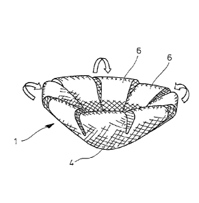
Figure 1 illustrates a first embodiment of a surgical implant,
which is designated by reference numeral 1.
In Figure 1(a), a basic structure 2 is shown in plan view. The
basic structure 2 comprises a primary region 4 in its center
area and a total of eight arms 6 starting from the periphery 8
of the primary region 4. Each arm 6 has a free end 10 and, ad-
jacent to its free 10, an end area 11.
The basic structure 2 is areal, i.e. made of relatively thin
material, and flexible. In the embodiment, it comprises a sur-
gical mesh, e.g. a "Vypro II" mesh (see above), which includes
multifilaments of "Vicryl" (absorbable) and polypropylene
(non-absorbable). Moreover, in the embodiment, the basic
structure 2 is made from one piece, e.g. by die-cutting.
Figure 1(b) shows the basic structure 2 after a protrusion 12
has been formed in the center area of the primary region 4.
Figure 1(c) displays the protrusion 12 in longitudinal section
in a plane perpendicular to the plane of Figure 1(b) and run-
ning through the center of the basic structure 2. In the em-
bodiment, the protrusion 12 has an elliptic curvature and is
atraumatic, i.e. it is designed as a low-profile tip. It is
formed by thermo-setting, which results in a stiffening effect
in the center area of the basic structure 2 and stabilizes the
primary region 4 of the implant 1. The protrusion 12 facili-
tates the handling of the implant 1 during surgery, can pre-
vent a tip of a grasping instrument from penetrating the basic
structure 2 and causing injury, and minimizes an irritation of
the peritoneum.
Figure 1(d) illustrates how the three-dimensional shape of the
implant 1 is formed. To this end, the arms 6 are folded back
CAN_DMS \136953805\1
Date Recue/Date Received 2020-12-14
- 11 -
towards the primary region 4, as indicated by the arrows, and
the end areas 11 of the arms 6 are fixed to the primary re-
gion, e.g. by ultrasonic welding, suturing or gluing (e.g. us-
ing poly-p-dioxanone as a glue). (To be precisely, Figure 1(d)
relates to a slight variant of the basic structure 2 of Fig-
ures 1(a) and (lb), in which the arms 6 are slightly wider.)
The protrusion 12 is not visible in Figure 1(d); it extends to
the bottom side, i.e. away from the arms 6.
Figure 2 shows a variant of the implant 1 of Figure 1, which
is designated by 1. Otherwise, the same reference numerals
are used as in Figure 1.
The implant 1 is reinforced and stiffened by reinforcement
elements fixed to the outer face of the basic structure 2 vis-
ible in Figure 2. In the embodiment, the reinforcement ele-
ments comprise a circular reinforcement band 14, which encir-
cles the protrusion 12, and radial reinforcement bands 16 ex-
tending along part of each arm 6. They are cut from a one-
piece blank of poly-p-dioxanone and welded to the basic struc-
ture before the arms 6 are folded. An increased stiffness of
the implant facilitates its placement during surgery. Poly-p-
dioxanone is absorbable so that, after some time, the stiff-
ness imposed by the reinforcement elements disappears. The re-
inforcement elements can be colored in order to enhance the
visibility of the implant during surgery.
Figure 3 shows another variant of the implant 1 of Figure 1,
which is designated by 1". Otherwise, the same reference nu-
merals are used as in Figure 1.
In the implant 1", each second arm 6" is longer than the other
arms 6, so that after back-folding the arms and attaching
their end areas to the primary region 4, the loops formed by
the arms 6" are greater than the loops formed by the arms 6.
When, during surgery, the implant 1" is to be fixed to bodily
tissue by suturing, the loops of the arms 6" can be preferably
used for taking up the sutures.
CAN_DMS \136953805\1
Date Recue/Date Received 2020-12-14
- 12 -
In the finished implants 1, 1 and 1", as shown in Figures
1(d), 2 and 3, the arms 6 and 6' form loops and together act
as a plug which can be easily grasped in a surgical procedure
and inserted into the defect to be repaired.
Another embodiment of a surgical implant, designated by 20, is
illustrated in Figure 4.
Figure 4(a) is a plan view of its basic structure 22, which is
cut in one piece from mesh material. The basic structure 22
defines a primary region 24 and a total of five arms 26, which
are separated by cut lines 27. Since the basic structure is
circular and the arms 27 are only separated by the cut lines
27, the free ends 28 of the arms 27 are defined by the circum-
ference line of the circle. After folding back, however, each
arm is attached to the primary region 24 in a small peripheral
area 29 only.
Figure 4(b) shows the result for the form of the implant after
folding back the arms and attachment to the primary region.
The implant of Figure 4(b) is a variant of the implant 20 and
designated by 20, because it comprises only four arms 26' in-
stead of five. Moreover, the curvature of the cut lines be-
tween the arms 26' is mirror-like compared to the curvature of
the cut lines 27 in Figure 4(a). The arms 26' can be rolled
somewhat about the inner parts of the implant 20, which re-
sults in the appearance shown in Figure 4(c).
Figure 5 displays another embodiment of the surgical implant,
here designated by 30.
The implant 30 comprises a circular basic structure 32, see
Figure 5(a). Its primary region 34 is reinforced by a circular
reinforcement band 35 consisting, in the embodiment, of poly-
p-dioxanone. Three arms 36 are separated by curved cut lines
37. In the inner parts of the cut lines 37, the arms are
CAN_DMS: \136953805\1
Date Recue/Date Received 2020-12-14
- 13 -
stiffened by redial reinforcement bands 38, which are pene-
trated by the cut lines 37.
Starting from the state shown in Figure 5(a), the arms 36 are
folded back towards the primary region 34 and are fixed, by
means of end areas 39, to the primary region 34. To this end,
the poly-p-dioxanone material of the circular reinforcement
band 35 is used as a melt-glue.
Figure 5(b) shows the three-dimensional shape of the implant
30. As with the other implants, the loops formed by the arms
can be pressed together when the implant is inserted in a her-
nia defect.
Many examples for suitable materials and compositions of the
basic structure, including composite structures, have already
been presented further above.
CAN_DMS: \136953805\1
Date Recue/Date Received 2020-12-14