Note: Descriptions are shown in the official language in which they were submitted.
CA 02890132 2015-04-30
WO 2014/096523
PCT/F12013/051137
1
COLUMN SHOE
Field of the invention
The invention relates to a column shoe as defined in the preamble of
independent claim
1.
The invention relates to column shoes which are used in lower ends of building
elements
of concrete, preferably precast building elements of concrete, such as in
lower end corners of
concrete columns or corresponding concrete element columns and/or in lower end
edges of
concrete columns or corresponding concrete element columns for securing the
building element
to bolts projecting from a base structure. A column shoe according to the
invention may however
also be used for securing wall elements of concrete to bolts projecting from a
base structure. A
column shoe according to the invention may however also be used for securing
walls of concrete
and beams of concrete and slabs of concrete to bolts projecting from a base
structure.
Publication WO 2012/056100 presents a column shoe for securing steel concrete
columns
to a base. The column shoe comprises a bolt housing, which comprises a
baseplate provided with
a bolt hole, and a sideplate, and attachment units fixedly connected to the
bolt housing for
securing the column shoe and the steel concrete column together.
Objective of the invention
The object of the invention is to provide a column shoe that provides for
increased
column shoe and connection shear force resistance and for increased column
shoe and
connection tension force resistance.
Short description of the invention
The column shoe is characterized by the definitions of independent claim 1.
Preferred embodiments of the column shoe are defined in the dependent claims.
In the column shoe the bolt housing is provided with at least one socket
member for
attaching an additional anchoring means such as a dowel or a bar to the column
shoe in addition
to at least one attachment unit and in addition to an anchor bolt.
The additional anchoring means, when fastened to a column shoe, increases
column shoe
and connection shear force resistance and increases column shoe and connection
tension force
resistance.
The additional anchoring means, when fastened to a column shoe, increases the
seismic
resistance.
The additional anchoring means, when fastened to a column shoe, increases the
pull-out
capacity of the column shoe in the horizontal direction.
The additional anchoring means may be in the form of a main bond, a
reinforcement bar,
or a dowel bar.
CA 02890132 2015-04-30
WO 2014/096523
PCT/F12013/051137
2
The additional anchoring means may be installed or attached to the bolt
housing after
casting of the column shoe into a building element of concrete. No
modifications to the
formwork for casting the concrete unit is therefore necessarily needed in
order to provide a bolt
housing with additional anchoring means.
The invention relates also to the use of a column shoe according to any of the
claims 1 to
for lifting a building element of concrete having at least one column shoe
according to any of
the claims 1 to 15 attached to the building element of concrete by attaching a
lifting member to a
socket member of the column shoe attached to the building element of concrete
and by lifting the
building element of concrete by lifting from the lifting member.
List of figures
In the following the invention will described in more detail by referring to
the figures, of
which
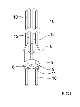
Figure 1 shows a column shoe according to a first embodiment,
Figure 2 shows the column shoe shown in figure 1 from above,
Figure 3 shows the column shoe shown in figure 1 from one side
Figure 4 shows the column shoe shown in figure 1 in partly cut view,
Figure 5 shows a column shoe according to a second embodiment,
Figure 6 shows the column shoe shown in figure 5 from above,
Figure 7 shows the column shoe shown in figure 5 from one side
Figure 8 shows the column shoe shown in figure 5 in partly cut view,
Figure 9 shows a column shoe according to a third embodiment,
Figure 10 shows the column shoe shown in figure 9 from above,
Figure 11 shows the column shoe shown in figure 9 from one side
Figure 12 shows the column shoe shown in figure 9 in partly cut view,
Figure 13 shows a column shoe according to a fourth embodiment,
Figure 14 shows the column shoe shown in figure 13 from above,
Figure 15 shows the column shoe shown in figure 13 from one side
Figure 16 shows the column shoe shown in figure 13 in partly cut view,
Figure 17 shows a column shoe according to a fifth embodiment,
Figure 18 shows the column shoe shown in figure 17 from above,
Figure 19 shows the column shoe shown in figure 17 from one side
Figure 20 shows the column shoe shown in figure 17 in partly cut view,
Figure 21 shows a concrete column provided with four column shoes according to
one
embodiment,
Figure 22 shows the concrete column shown in figure 21 as seen from below,
Figure 23 shows a concrete column provided with four column shoes according to
the
first embodiment shown in figures 1 to 4,
CA 02890132 2015-04-30
WO 2014/096523
PCT/F12013/051137
3
Figure 24 shows the concrete column shown in figure 23 as seen from below,
Figure 25 shows a concrete column provided with four column shoes according to
another embodiment,
Figure 26 shows the concrete column shown in figure 25 as seen from below,
Figure 27 shows a concrete column provided with four column shoes according to
yet
another embodiment,
Figure 28 shows the concrete column shown in figure 27 as seen from below,
Figure 29 shows a concrete column provided with four column shoes according to
the
third embodiment shown in figures 9 to 12,
Figure 30 shows the concrete column shown in figure 29 as seen from below,
Figure 31 shows a concrete column provided with four column shoes according to
still
another embodiment,
Figure 32 shows the concrete column shown in figure 31 as seen from below,
Figure 33 shows a concrete column provided with four column shoes according to
the
fifth embodiment shown in figures 17 to 20,
Figure 34 shows the concrete column shown in figure 33 as seen from below,
Figure 35 shows a concrete column provided with four column shoes according to
another embodiment of the column shoe, where a lifting loop is fastened to one
column shoe,
Figure 36 shows a concrete column provided with four column shoes according to
another embodiment of the column shoe, where a lifting device is fastened to
the four column
shoes,
Figure 37 shows a concrete column provided with four column shoes according to
another embodiment of the column shoe where a lifting ring is fastened to one
column shoe, and
Figure 38 shows a concrete column attached to a base by means of column shoes.
Detailed description of the invention
Figures 1 to 20 show five different embodiments of a column shoe 1 for
securing
building elements of concrete such as concrete columns to a base 3 such as a
foundation of a
building or a corresponding load-bearing structure. The building element of
concrete is
preferably in the form of a precast building element of concrete such as a
precast concrete
column, which means that the building element of concrete is manufactured at a
location
different from the construction site where the building element is used in a
building. The
building element can also be in the form of a wall element of concrete, a
precast wall element of
concrete, a beam of concrete, a precast beam of concrete, a slab of concrete,
or a precast slab of
concrete.
Figures 21 to 34 show seven different concrete columns 2 each provided with
four
column shoes 1 so that each lower corner of each concrete column 2 is provided
with a column
shoe 1.
CA 02890132 2015-04-30
WO 2014/096523
PCT/F12013/051137
4
The column shoe 1 comprises a bolt housing 4 that comprises a baseplate 5
provided with
a through bolt hole 6 for an anchor bolt 7 which is partly arranged in the
baseplate 5 so that the
anchor bolt 7 projects from the base 3. The anchor bolt 7 may be provided with
treads (not
shown) for nuts (not shown) in order to secure the bolt housing 4 of the
column shoe 1 to the
base 3.
The bolt housing 4 comprises additionally an upper structure 8 connected to
the baseplate
5.
The column shoe 1 comprises additionally at least one attachment unit 12
attached to the
bolt housing 4 for securing the column shoe 1 and the concrete column 2
together. A such
attachment unit 12 may be fixedly or releasable attached to the bolt housing
4.
The bolt housing 4 is provided with at least one socket member 9 for attaching
an
additional anchoring means 10 such as a dowel, as is shown in figures 9 to 16
and 27 to 32, or a
bar, as is shown in figures 1 to 8 and 17 to 26 and 33 to 34, to the column
shoe 1 in addition to at
least one attachment unit 12 and in addition to an anchor bolt 7.
A purpose of the attachment unit 12 is to transfer loads between the building
element of
concrete, into which the column shoe is to be at least partly cast, and the
base 3. Such loads may
include any of the following: shear force, tension, bending, torque and
pressure.
The number of socket members 9 per column shoe 1 may vary. The figures show
column
shoes 1 having one, two, or three socket members 9.
The column shoe 1 comprises preferably, but not necessarily, a socket member 9
comprising a hole 11 for at least partly receiving an additional anchoring
means 10.
The column shoe 1 comprises, as shown in figures 1 to 16, at least one a
socket member
9 comprising a hole 11 in the form of a cylindrical through hole for at least
partly receiving an
additional anchoring means 10.
The column shoe 1 may, as shown in figures 17 to 20, comprise at least one a
socket
member 9 comprising a hole 11 in the form of a cylindrical blind hole for at
least partly
receiving an additional anchoring means 10.
The hole 11 of the socket member 9 is provided with an inner threading 13 for
co-
operation with an outer threading 14 of at least one additional anchoring
means 10.
The inner threading 13 extends over the whole length of the hole 11. In
practice this
means that if the socket member 9 comprises a hole 11 in the form of a
cylindrical through hole
having an inner threading 13 extending over the whole length of the
cylindrical through hole,
one additional anchoring means 10 can be fastened at both ends of the
cylindrical through hole.
For example in the embodiments shown in figures 1 to 16, two additional
anchoring means 10
are attached to each socket member 9 so that one additional anchoring means 10
is attached
using the inner threading 13 of the cylindrical through hole at one end of the
cylindrical through
hole and so that another additional anchoring means 10 is attached using the
inner threading 13
of the cylindrical through hole at the opposite end of the cylindrical through
hole.
CA 02890132 2015-04-30
WO 2014/096523
PCT/F12013/051137
If the column shoe 1 comprises a socket member 9 comprising a hole 11, the
hole 11 is
preferably, but not necessarily, a cylindrical hole, such as a through or
blind hole, having a first
central axis that is parallel with a second central axis of a cylindrical
through bolt hole 6 in the
baseplate 5 of the bolt housing 4, provided that the through bolt hole 6 in
the baseplate 5 of the
5 bolt housing 4 is in the form of a cylindrical through bolt hole 6
Instead of or in addition to the bolt housing 4 only being provided with at
least one socket
member 9 for attaching an additional anchoring means 10 to the bolt housing 4,
the column shoe
1 may be provided with an additional anchoring means 10. Such additional
anchoring means 10
may be arranged at least partly in a socket member 9 so that the additional
anchoring means 10 is
fastened to the bolt housing 4 by means of a positive connection between the
socket member 9
and the additional anchoring means 10. It is also possible that the column
shoe 1 is provided with
an additional anchoring means 10 having an outer threading 14 and that the
socket member 9
comprising a hole 11 provided an inner threading 13 for cooperation with the
outer threading 14
of the additional anchoring means 10, whereby the additional anchoring means
10 is arranged at
least partly in the hole 11 of the socket member 9 so that the additional
anchoring means 10 is
fastened to the bolt housing 4 by means of the inner threading 13 in the hole
11 of the socket
member 9 and the outer threading 14 of the additional anchoring means 10.
The bolt housing 4 may be a casted one-piece structure or a structure formed
by welding
together several sub-structures such as a baseplate 5 and an upper structure
8.
The column shoe 1 may comprise a socket member 9 that is an integrated part of
at least
one of the upper structure 8 of the bolt housing 4 and the baseplate 5 of the
bolt housing 4.
Especially if the bolt housing 4 is a casted one-piece structure it may be of
an advantage to
provide the bolt housing 4 with integrated casted socket members 9 in
connection with the
casting of the bolt housing 4.
The column shoe 1 may comprise a socket member 9 that is an external structure
of the
bolt housing 4 and that is fixedly of releasable attached to at least one of
the upper structure 8 of
the bolt housing 4 and the baseplate 5 of the bolt housing 4.
The column shoe 1 may comprise a socket member 9 that is at least partly
formed in at
least one of the upper structure 8 of the bolt housing 4 and the baseplate 5
of the bolt housing 4.
The column shoe 1 may comprise a socket member 9 that is formed fully within
the
baseplate 5 of the bolt housing 4 of the bolt housing 4 as is the case in the
fifth embodiment of
the column shoe 1 shown in figures 17 to 20.
The column shoe 1 may comprise a socket member 9 for attaching an additional
anchoring means 10 in the form of a main bond. It is also possible that the
column shoe 1
comprises a socket member 9 for attaching an additional anchoring means 10 in
the form of a
main bond and an additional anchoring means 10 in the form of a main bond
fastened to said
socket member 9 for attaching an additional anchoring means 10 in the form of
a main bond.
The column shoe 1 may comprise a socket member 9 for attaching an additional
CA 02890132 2015-04-30
WO 2014/096523
PCT/F12013/051137
6
anchoring means 10 in the form of a reinforcement bar. It is also possible
that the column shoe 1
comprises a socket member 9 for attaching an additional anchoring means 10 in
the form of a
reinforcement bar and an additional anchoring means 10 in the form of a
reinforcement bar
fastened to said socket member 9 for attaching an additional anchoring means
10 in the form of a
reinforcement bar.
The column shoe 1 may comprise a socket member 9 for attaching an additional
anchoring means 10 in the form of a dowel bar. It is also possible that the
column shoe 1
comprises a socket member 9 for attaching an additional anchoring means 10 in
the form of a
dowel bar and an additional anchoring means 10 in the form of a dowel bar
fastened to said
socket member 9 for attaching an additional anchoring means 10 in the form of
a dowel bar.
A column shoe 1 as described here and that is fastened to a building element
of concrete
may be used lifting the building element of concrete by attaching a lifting
member 15 to the
socket member 9 of the column shoe 1 as is shown in figures 35 to 37 and by
lifting the building
element of concrete from the lifting member 15.
It is apparent to a person skilled in the art that as technology advances, the
basic idea of
the invention can be implemented in various ways. The invention and its
embodiments are
therefore not restricted to the above examples, but they may vary within the
scope of the claims.