Note: Descriptions are shown in the official language in which they were submitted.
CA 02890420 2015-05-04
WO 2014/074321
PCT/1JS2013/066556
DOUBLE SHAFT DRILLING APPARATUS WITH HANGER
BEARINGS
BACKGROUND OF THE DISCLOSURE
1. Technical field
[0001] This invention relates generally to drilling motors for drilling
boreholes
into the earth. In particular, an apparatus of the present disclosure relates
to a drilling
motor powered by transmission of a drilling fluid therethrough.
2. Description of Related Art
[0002] Often in down-hole drilling operations, a down-hole drilling motor is
suspended from the lower end of a string of drill pipe. A drilling fluid may
be
transmitted through the drill string and circulated or passed through the
drilling motor
to induce rotation of a drill bit. The rotating drill bit engages a
subterranean
formation to produce a borehole therein. In the drilling environment, the
space
available for equipment is limited at least in part by the size of the
borehole to be
drilled.
[00031 To drive the drill bit, a torque must often be transmitted from a power
section of the motor that is remotely disposed with respect to the drill bit.
In some
instances, the torque must be transmitted past equipment that occupies a
portion of the
available space. Thus, the drive components, i.e., the mechanisms employed to
transmit the torque, must often operate with a degree of axial misalignment
between
the drive components. Also, the drive components often operate in a harsh
environment since the drilling fluid used to drive the motor may be passed
through the
space occupied by the drive components. The flow of the drilling fluid may
tend to
erode or "wash out" some of the drive components, and in some instances, the
tendency to wash out the drive components may be exacerbated by a tortuous
fluid
flow path defined by the drive components. Accordingly, to accommodate the
limited
space and the harsh environment, consideration must be taken in the design of
a
down-hole drilling apparatus.
CA 02890420 2015-05-04
WO 2014/074321
PCT/US2013/066556
SUMMARY OF THE DISCLOSURE
[0004] In one embodiment of the present disclosure, a drilling apparatus
includes a housing defining a longitudinal axis. A power section of the
apparatus
includes a rotor adapted to move with eccentric rotary motion with respect to
the
longitudinal axis in response to the passage of drilling fluids through the
power
section. A power transmission shaft is provided having an upper end and a
lower end.
The upper end of the power transmission shaft is coupled to the rotor such
that the
upper end of the power transmission shaft is movable with the eccentric motion
of the
rotor. The lower end of the power transmission shaft is constrained to rotate
in a
concentric manner with respect to the longitudinal axis. A generally rigid
torsion rod
has an upper end and a lower end. The upper and lower ends of the torsion rod
are
constrained to rotate in a concentric manner with respect to the longitudinal
axis, and
the upper end of the torsion rod is coupled to the lower end of the power
transmission
shaft such that a torque may be transmitted from the power transmission shaft
to the
torsion rod. A mandrel is interconnected with the lower end of the torsion rod
such
that a torque may be transmitted from the torsion rod to the mandrel, the
mandrel
including a connection for a drill bit.
[0005] According to another embodiment of the present disclosure, a drilling
apparatus includes a housing defining a longitudinal axis and a nominal
internal
diameter. The housing includes a relatively narrow section that exhibits a
limited
internal diameter that is less than the nominal internal diameter. A payload
bay
disposed adjacent relatively narrow section of the housing, and a torsion rod
is
disposed in the relatively narrow section of the housing. The torsion rod is
supported
to rotate concentrically about the longitudinal axis. A power section includes
a rotor,
and the rotor is adapted to move with eccentric rotary motion with respect to
the
longitudinal axis in response to the passage of drilling fluids through the
power
section. A power transmission shaft is interconnected between the rotor and
the
torsion rod such that herein an upper end of the power transmission shaft is
movable
with the eccentric rotary motion of the rotor and a lower end of the power
transmission shaft is movable with the concentric motion of the torsion rod. A
mandrel for supporting a drill bit is coupled to and driven by the torsion
rod.
2
[0006] According to another embodiment of the present disclosure, a method of
operating a drilling apparatus comprises the steps of: (a) providing a power
section including a
rotor, wherein the rotor is adapted to move with eccentric rotary motion with
respect to a
longitudinal axis in response to the passage of drilling fluids through the
power section, (b)
providing a power transmission shaft having an upper end coupled to the rotor
and movable
with the eccentric rotary motion of the rotor and a lower end constrained to
move with
concentric rotary motion with respect to the longitudinal axis, (c) providing
a torsion bar
coupled to the lower end of the power transmission shaft and movable with the
concentric
rotary motion of the lower end of the power transmission shaft, (d) providing
a mandrel
coupled to the torsion bar, the mandrel rotatable in response to rotation of
the torsion bar, and
(e) passing a drilling fluid through the power section to move the rotor,
thereby inducing
eccentric rotary motion of the upper end of the power transmission shaft,
concentric rotary
motion of the lower end of the power transmission shaft, concentric rotary
motion of the
torsion bar, and rotation of the mandrel.
[0006a] According to another embodiment of the present disclosure, there is
provided a
drilling apparatus comprising: a housing defining a longitudinal axis; a power
section including
a rotor, wherein the rotor is adapted to move with eccentric rotary motion
with respect to the
longitudinal axis in response to the passage of drilling fluids through the
power section; a
power transmission shaft having an upper end and a lower end, the upper end of
the power
transmission shaft coupled to the rotor such that the upper end of the power
transmission shaft
is movable with the eccentric motion of the rotor, and wherein the lower end
of the power
transmission shaft is constrained to rotate in a concentric manner with
respect to the
longitudinal axis; a generally rigid torsion rod having an upper end and a
lower end, wherein
the upper and lower ends of the torsion rod are each constrained to rotate in
a concentric
manner with respect to the longitudinal axis, and wherein the upper end of the
torsion rod is
coupled to the lower end of the power transmission shaft such that a torque
may be transmitted
from the power transmission shaft to the torsion rod; and a mandrel
interconnected with the
lower end of the torsion rod by at least one flexible coupling such that the
torque may be
transmitted from the torsion rod to the mandrel, the mandrel disposed at an
oblique angle with
respect to the longitudinal axis, the mandrel including a connection for a
drill bit.
3
CA 2890420 2018-11-09
[0006b] According to another embodiment of the present disclosure, there is
provided
a drilling apparatus comprising: a housing defining a longitudinal axis and a
nominal internal
diameter, the housing including a relatively narrow section that exhibits a
limited internal
diameter that is less than the nominal internal diameter; a payload bay
disposed adjacent
relatively narrow section of the housing; a torsion rod disposed in the
relatively narrow section
of the housing, the torsion rod supported to rotate concentrically about the
longitudinal axis,
the torsion rod including a relatively narrow midsection positioned in
substantial alignment
with the relatively narrow section of the housing; a power section including a
rotor, wherein
the rotor is adapted to move with eccentric rotary motion with respect to the
longitudinal axis
in response to the passage of drilling fluids through the power section; a
power transmission
shaft interconnected between the rotor and the torsion rod, wherein an upper
end of the power
transmission shaft is movable with the eccentric rotary motion of the rotor,
and wherein a
lower end of the power transmission shaft is movable with the concentric
motion of the torsion
rod; and a mandrel for supporting a drill bit coupled to and driven by the
torsion rod, the
mandrel coupled to the torsion rod by at least one flexible coupling, the
mandrel disposed at
an oblique angle with respect to the longitudinal axis.
[0006c] According to another embodiment of the present disclosure, there is
provided
a method of operating a drilling apparatus, the method comprising the steps
of: providing a
power section including a rotor, wherein the rotor is adapted to move with
eccentric rotary
motion with respect to a longitudinal axis in response to the passage of
drilling fluids through
the power section; providing a power transmission shaft having an upper end
coupled to the
rotor and movable with the eccentric rotary motion of the rotor and a lower
end constrained to
move with concentric rotary motion with respect to the longitudinal axis;
providing a torsion
bar coupled to the lower end of the power transmission shaft and movable with
the concentric
rotary motion of the lower end of the power transmission shaft; providing a
mandrel coupled
to the torsion bar by at least one flexible coupling, the mandrel disposed at
an oblique angle
with respect to the longitudinal axis, the mandrel rotatable in response to
rotation of the
torsion bar; and passing a drilling fluid through the power section to move
the rotor, thereby
inducing eccentric rotary motion of the upper end of the power transmission
shaft. concentric
3a
CA 2890420 2017-06-19
rotary motion of the lower end of the power transmission shaft, concentric
rotary motion of the
torsion bar, and rotation of the mandrel.
BRIEF DESCRIPTION OF THE DRAWINGS
[0007] The present disclosure is best understood from the following detailed
description when read with the accompanying figures. In accordance with the
standard
practice in the industry, various features may not be drawn to scale.
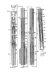
[0008] FIG. 1 is cross-sectional side view of a drilling apparatus, which
includes a
power section, a bearing section, and a transmission section therebetween in
accordance with
one or more aspects of the present disclosure.
[0009] FIG. 2 is an enlarged view of the area of interest "A" identified FIG.
1, which
depicts an upper hanger bearing.
[0010] FIG. 3 is an enlarged view of the area of interest "B" identified FIG.
1, which
depicts a lower hanger bearing.
[0011] FIGS. 4A and 4B are respectively front and cross sectional side views
of an
alternate embodiment of a hanger bearing in accordance with one or more
aspects of the
present disclosure depicting an annular drilling fluid flow path around the
hanger bearing.
[0012] FIG. 5 is a cross-sectional side view of an alternate embodiment of a
hanger
bearing through which an interior drilling fluid flow path is defined.
3b
CA 2890420 2017-06-19
CA 02890420 2015-05-04
WO 2014/074321
PCT/US2013/066556
DESCRIPTION OF EMBODIMENTS
[0013] It is to be understood that the following disclosure provides many
different embodiments, or examples, for implementing different features of
various
embodiments. Specific examples of components and arrangements are described
below to simplify the present disclosure. These are, of course, merely
examples and
are not intended to be limiting.
[0014] FIG. 1 depicts a longitudinal cross-section of a drilling apparatus 10
of
the present disclosure. The apparatus 10 generally includes a power section 12
at an
upper end thereof, a bearing section 16 at a lower end, and a transmission
section 18
therebetween. As used herein, the term "upper" refers to a direction or side
of a
component that is oriented toward the surface of a borehole, while the term
"lower
refers" to the direction or side of a component oriented toward the portion of
the
borehole most distant from the surface. The power section 12 is adapted to
provide
rotary motion to a drill bit "B," which may be coupled to a lower end of the
bearing
section 16. The transmission section 18 is adapted to transmit rotary motion
produced
in the power section 12 to the bearing section 16. The power section 12
defines a
central longitudinal axis X-X, and the bearing section 16 defines an axis Y-Y
that is
disposed at a bend angle "a" with respect to the longitudinal axis X-X. The
angle "a"
may lie in the range of about 0 to about 4 degrees, and thus, the bearing
section 16
may support rotary motion of drill bit "B" at an oblique angle with respect to
the
power section 12.
[0015] The power section 12 includes a top subassembly or top sub 20 at an
upper end thereof. The top sub 20 has a threaded tubular connection 22 at its
upper
end, for coupling the apparatus 10 to a drill string "S" disposed above the
apparatus
10. The drill string "S" may include multiple sections of drill pipe and/or
drill collars
interconnected with one another in an end to end manner, and may thus
interconnect
the apparatus 10 to equipment at the surface of a borehole.
[0016] The power section 12 further includes a stator 30 fixedly supported by
a lower end of the top sub 20. The stator 30 defines a helically contoured
inner
surface 30a, which circumscribes a rotor 32. The rotor 32 defines a helically
contoured outer surface 32a, which is configured to engage the helically
contoured
inner surface 30a of the stator 30 inner surface to guide motion of the rotor.
The
stator 30 and rotor 32 together may comprise a "Moineau," or positive
displacement
4
CA 02890420 2015-05-04
WO 2014/074321
PCT/US2013/066556
type motor that is operated by the passage of drilling fluids (or mud)
therethrough. A
drilling fluid may be pumped down through the drill string "S" and through the
stator
30 to induce the rotor 32 to simultaneously rotate about an axis R-R defined
through
the rotor 32 and orbit or roll around the inner surface 30a of the stator 30.
Depending
in part on the particular geometry of the contoured surfaces 30a, 32a, the
orbital
motion of the rotor 32 may be generally circular, elliptical, polygonal or may
follow
an alternate path. The rotary motion of the rotor 32 may be generally
characterized as
eccentric motion with respect to the longitudinal axis X-X since components of
the
rotary motion may not be aligned with the axis X-X.
[0017] A rotor catch rod 36 is coupled to an upper end of the rotor 32 such
that the rotor catch rod nominally moves with the eccentric motion of the
rotor 32.
The rotor catch rod 36 extends through a rotor catch ring 38, which is secured
to the
stator 30 and provides clearance for the nominal movement of a relatively
narrow
portion 36a of the rotor catch rod 36. However, in the event of a breakage or
failure
within the apparatus 10 that permits the rotor 32 to fall with respect to the
stator 30,
the rotor catch ring 38 will generate an interference with a relatively broad
portion
36b of the rotor catch rod 36. Thus, the rotor catch rod 36 together with the
rotor
catch ring 38 serve to "catch" or interrupt the falling of the rotor 32 and
any of the
components connected thereto.
[0018] Below the power section 12 the transmission section includes an outer
housing 40 coupled to the stator 30 such that the outer housing remains
relatively
stationary with respect to the stator 30 and top sub 20. The outer housing 40
may
include multiple sections 40a, 40b, 40c and 40d along its length, which are
coupled to
one another by a threaded or similar connection in alignment with the
longitudinal
axis X-X. The outer housing section 40a defines a nominal internal diameter
designated "N."
[0019] A power transmission shaft includes flexible shaft 42, and is disposed
within the outer housing section 40a. The flexible shaft 42 is constructed of
a
conformable material that is capable of transmitting a torque therethrough. An
upper
end 42a of the flexible shaft 42 is coupled to the rotor 32 and receives
eccentric rotary
motion therefrom. A lower end 42b of the flexible shaft 42 is coupled to a
first or
upper hanger bearing 44, which serves to constrain the rotation of the lower
end 42b
of the flexible shaft in a concentric manner, e.g., constrains the movement to
rotation
about the longitudinal axis X-X. Thus, the conformable nature of the flexible
shaft 42 permits
the flexible shaft 42 to serve as a transmission that converts the eccentric
motion of rotor 32 to
concentric motion. The power transmission shaft may include other mechanisms
to
accommodate the conversion of eccentric motion to concentric motion. For
example, the
power transmission shaft may include a universal joint, or a constant-velocity
joint (CV joint)
configured to transmit torque at a constant rotational speed through a
variable angle. Many CV
joints include a pair of circumferential flanges with roller bearings disposed
therebetween to
accommodate the variable angle. The power transmission shaft may also include
a knuckle
joint 64 as described below.
[0020] An upper end 48a of a torsion rod 48 is coupled to the hanger bearing
44
opposite the flexible shaft 42 such that concentric movement of the hanger
bearing 44 may be
transmitted to the torsion rod 48. The torsion rod 48 may be considered to
"hang" from the
hanger bearing 44. A lower end 48b of the torsion rod 48 is coupled to a
second or lower
hanger bearing 52, which constrains rotation of the lower end 48b of the
torsion rod 48 in a
concentric manner. The torsion rod 48 may be constructed of a substantially
rigid material
such as steel, and may exhibit a relatively narrow midsection 48c. The narrow
midsection 48c
is generally adjacent and parallel to a payload bay 56 disposed on the outer
housing section
40b. The payload bay 56 may carry equipment to facilitate a drilling operation
such as a
sensor and data transmission assembly "W" for use in a measure-while-drilling
(MWD) or
logging-while-drilling (LWD) system. An MWD or LWD system may provide the
capability
to transmit signals representative of a drilling condition into a nearby rock
formation "F" and
to the surface. A more detailed description of an MWD or LWD may be found in
commonly
owned U.S. Patent Nos. 7,518,528 and 8,069,716.
[0021] The payload bay 56 occupies a portion of the radial space provided by
the outer
housing section 40b, and thus, a limited or minimum internal diameter "M" is
defined adjacent
the payload bay 56. The minimum internal diameter "M" limits the size, and
thus the
robustness, of the relatively narrow midsection 48c of the torsion bar 48.
[0022] A first drive coupling or adapter 58 is coupled to the lower hanger
bearing 52
opposite the torsion rod 48. The adapter 58 transmits torque to a first
6
CA 2890420 2018-11-09
CA 02890420 2015-05-04
WO 2014/074321
PCT/US2013/066556
driven rod 60, which is coupled to and transmits torque a second drive
coupling or
adapter 62. Together, the driven rod 60 and the adapters 58, 62 define a
knuckle joint
64 and permit the apparatus 10 to transmit torque through the angle "a" to the
bearing
section 16. The adapters 58, 62 may comprise, e.g., knuckle couplings capable
of
accommodating up to a 6 bend, or alternatively, the driven rod 60 may
comprise a
flexible shaft or coupling. It is contemplated that adapters 58, 62, driven
rod 60 other
drive transmission components described herein, e.g., flexible shaft 42,
hanger
bearings 44, 52 and torsion rod 48, may be attached by known latching
mechanisms
such as a combination of pins and set screws. Other methods of attachment will
be
apparent to those of ordinary skill in the art.
[0023] The bearing section 16 generally includes a bearing housing 66
coupled to the outer housing section 40d at the angle "a" relative to the
longitudinal
axis X-X. An end nut 68 is coupled to bearing housing 66 defines a lower-most
housing component for the drilling apparatus 10. A flow diverter 70 and
mandrel 72
are disposed within the bearing housing 66 and are rotatable about the axis Y-
Y. The
flow diverter 70 is coupled to the second adapter 62 such that torque may be
transmitted from the second adapter 62 to the flow diverter 70. Similarly the
mandrel
72 is coupled to the flow diverter 70 such that torque may be transmitted from
the
flow diverter 70 to the mandrel 72. Rotation of the flow diverter 70 and
mandrel 72 is
supported by upper and lower radial bearings 76, 78, and by a thrust bearing
package
80 disposed axially therebetween. The radial bearings 76 and 78 accommodate
radial
loads experienced by the drill bit "B", and may comprise at least one annular
member
defining a circumferential bearing surface. The radial bearings 76 and 78 may
be
constructed, e.g., from cemented tungsten carbide, or a suitable ceramic,
metal, or
other bearing material. The thrust bearing package 80 is provided primarily to
accommodate vertical or longitudinal loads, e.g., loads directed along axis Y-
Y, and
may comprise ball bearings movable through annular races, polycrystalline
diamond
compact (PDC) bearings, or other suitable arrangements as known in the art.
[0024] The mandrel 72 provides a threaded connection 84 for engaging the
drill bit "B" such that torque and rotary motion may be transmitted from the
mandrel
72 to the drill bit "B." Thus, in operation, the drill bit "B" is operatively
coupled to
the rotor 32 to receive torque and rotary motion therefrom. The torque and
rotary
motion transmitted from the rotor 32 through the flexible shaft 42, upper
hanger
7
CA 02890420 2015-05-04
WO 2014/074321
PCT/US2013/066556
bearing 44, torsion bar 48, lower hanger bearing 52, adapter 58, driven rod
60, adapter
62, flow diverter 70 and mandrel 72 to drive the drill bit "B."
[0025] Drilling fluid that is pumped through the drill string "S" to drive the
rotor 32 flows through the power section 12 into the transmission section 18
where it
flows generally in the annular space between the outer housing 40 and the
drive
components, which include the flexible shaft 42, upper hanger bearing 44,
torsion rod
48, lower hanger bearing 52, adapter 58, driven rod 60 and adapter 62 Upon
entering
the bearing section 16, the flow diverter 70 operates to divert a portion of
the drilling
fluid exiting the transmission section 18 into a passage of the 82 of the
drilling
mandrel 72. Another portion of the drilling fluid may flow in annular space
between
the bearing housing 66 and the mandrel 72 and may serve to lubricate the
bearings 76,
78 and 80. Drilling fluid that passes through the passage 82 may flow through
the
drill bit "B" into the borehole, and may be recirculated through the annular
space
between the apparatus 10 and the formation "F."
[0026] In other embodiments (not shown), the knuckle joint 64 may be
replaced with alternate flexible couplings known in the art. For example, a CV
joint,
universal joint, flexible shaft, or similar mechanism may be employed to
accommodate the oblique angle "a" of the mandrel 72 with respect to the
longitudinal
axis X-X.
[0027] Referring now to FIG. 2, the upper hanger bearing 44, and a drilling
fluid flow path around flexible shaft 42, upper in the vicinity of the upper
hanger
bearing 44 is depicted. The hanger bearing 44 includes a generally solid body
44a
and a plurality of fins 44b that project radially therefrom. The fins 44b
define an
annular array and engage a generally cylindrical outer radial bearing 88. A
fluid flow
path is defined in the voids between the fins 44b, the body 44a and the outer
radial
bearing 88 as indicated by arrows "P." The fluid flow path is maintained
generally in
an annular space as it passes the flexible shaft 42, hanger bearing 44 and
torsion rod
48. By maintaining an annular flow path around the solid body 44a of the
hanger
bearing 44, rather than directing fluid through a passageway (not shown)
through the
hanger bearing 44, e.g., the degree of erosion of the hanger bearing 44 by the
drilling
fluid may be limited.
[0028] The outer radial bearing 88 may be rotationally fixed by spacers 90
disposed longitudinally between the outer radial bearing 88 and the outer
housing
8
CA 02890420 2015-05-04
WO 2014/074321
PCT/US2013/066556
section 40c. The spacers 90 may form an interferences fit, or may be held in
compression by the end nut 68 (FIG. 1).
[0029] Referring now to FIG. 3, a similar flow path is established in the
vicinity of lower hanger bearing 52. The fluid flow path, denoted by arrows
"P," is
maintained generally in the annular space between the torsion rod 48 and the
outer
housing section 40b. The drilling fluid may then pass the lower hanger bearing
52 in
an array of voids defined between hanger bearing body 52a, radially extending
fins
52b and an outer radial bearing 92. The drilling fluid maintains a generally
annular
flow path as it flows past the adapter 58 and driven rod 60.
[0030] Referring now to FIGS. 4A and 4B, an alternate configuration of a
hanger bearing 102 and outer radial bearing 104 is depicted. The hanger
bearing 102
defines a generally cylindrical or circular outer circumferential surface
102a. The
circumferential surface 102a defines a bearing surface that engages an inner
circumferential surface 104a of the outer radial bearing 104. The inner
circumferential surface 104a is interrupted by longitudinal grooves 104b
formed in
the outer radial bearing 104. The longitudinal grooves 104b provide a fluid
flow path
for drilling fluids as indicated by arrows "P1 ." The longitudinal grooves
104b may
remain relatively stationary relative to rotational motion of the hanger
bearing 102
about a central axis Z-Z.
[0031] Referring now to FIG. 5, another alternate configuration of a hanger
bearing 112 and outer radial bearing 114 is depicted. The hanger bearing 112
defines
a generally cylindrical or circular outer circumferential surface 112a, which
defines a
bearing surface that engages generally circular inner circumferential surface
114a
defined by the outer radial bearing 114. The outer and inner circumferential
surfaces
112a and 114a are both generally continuous, and thus, only a relatively small
portion
of the drilling fluid is permitted to pass between the outer and inner
circumferential
surfaces 112a and 114a, e.g. to lubricate the bearing surfaces 112a and 114a.
An
interior passageway 116 is defined through the hanger bearing 112 and defines
a
drilling fluid flow path therethrough as indicated by arrows "P2." The fluid
flow path
indicated by arrows "P2" is generally annularly shaped about an upper drive
component such as power transmission shaft 42 and about a lower drive
component
such as adapter 58. An inlet 116a transitions the annular shape of the fluid
flow path
around the power transmission shaft 42 to the shape of the interior passageway
116.
9
An outlet 116b transitions the shape of the interior passageway to the annular
shape around the
adapter 58. Although the hanger bearing 112 is depicted as connecting the
power transmission
shaft 42 and adapter 58, the hanger bearing 112 may be provided between any of
the drive
components discussed above and the hanger bearing 112 may be incorporated in
place of any
of the hanger bearings 44, 52, 102 discussed above.
[0032] The foregoing outlines features of several embodiments so that a person
of
ordinary skill in the art may better understand the aspects of the present
disclosure. Such
features may be replaced by any one of numerous equivalent alternatives, only
some of which
are disclosed herein. One of ordinary skill in the art should appreciate that
they may readily
use the present disclosure as a basis for designing or modifying other
processes and structures
for carrying out the same purposes and/or achieving the same advantages of the
embodiments
introduced herein. One of ordinary skill in the art should also realize that
such equivalent
constructions do not depart from the spirit and scope of the present
disclosure, and that they
may make various changes, substitutions and alterations herein without
departing from the
spirit and scope of the present disclosure.
[0033] The Abstract at the end of this disclosure is provided to allow the
reader to
quickly ascertain the nature of the technical disclosure. It is submitted with
the understanding
that it will not be used to interpret or limit the scope or meaning of the
claims.
CA 2890420 2017-06-19