Note: Descriptions are shown in the official language in which they were submitted.
COAXIAL BI-DIRECTIONAL CATHETER
10
TECHNICAL FIELD
This application relates to medical devices, and more particularly, to medical
catheters with steering capabilities for use in tracking tortuous pathways or
deflecting
and/or placing accessories.
BACKGROUND
The concept of a variable stiffness microcatheter for use in navigating into
tortuous narrow vasculature for delivery of treatment options such as fluid
injection or
coil placement is disclosed in U.S. Patent Number 4,739,786, to Engelson. This
is
achieved by steam shaping the variable stiffness catheter's distal tip and
tracking the
catheter in combination with a guidewire, straight or curved. While this
method allows
for quick, accurate access to remote areas such as those in the brain, it does
not allow for
slight distal tip adjustments to aid in treatment once the destination site is
reached. If
adjustments are needed, the catheter or the guidewire, or in some instances
both, would
have to be removed and re-shaped.
U.S. Patent Number 6,726,700, to Levine, and U.S. Patent Number 7,591,813, to
Levine et al., attempted to correct this shortcoming by disclosing a
microcatheter with a
deflectable distal tip. Levine describes a co-linear catheter comprising a
flexible joint or
hinge region defining a main lumen, used for delivery of guidewires and
accessories, and
1
CA 2890745 2019-10-01
CA 02890745 2015-05-06
WO 2014/074986
PCT/US2013/069435
a wire lumen that contains a push/pull wire, which is secured to the distal
tip with a
radiopaque band. Flexion, or bending, of the hinge region is achieved through
remote
manipulation of the push/pull wire. While this design might work well on a
laboratory
bench top or in straight vasculature, it fails to consistently deflect in
narrow, tortuous
anatomy due to its co-linear design featuring the push/pull wire/hinge
construction and
the inability to introduce fluid into the wire lumen to act as a lubricant to
aid in reducing
friction between the movable push/pull wire and the wire lumen.
Both of the Levine patents disclose a co-linear, dual lumen (main lumen and
wire
lumen) deflectable catheter with tip deflection that is brought about through
manipulation
of a push/pull wire residing in the wire lumen which cannot be lubricated with
fluid.
Neither of the above mentioned devices disclose a coaxial (inner catheter and
outer
catheter) device that uses manipulation of the main lumen (inner catheter) and
lubrication
to bring about smooth, consistent deflection needed to aid in navigation along
a small
diameter tortuous pathway and to allow for slight tip adjustments to ensure
accuracy in
delivering fluids and accessories upon arrival at the desired site, as
disclosed herein.
SUMMARY
The present invention provides a coaxial bi-directional deflectable catheter
which
overcomes the above discussed limitations in tip manipulation in narrow,
tortuous
anatomy.
The present invention provides in one aspect a deflectable catheter comprising
an
outer member having a proximal portion and a distal portion, an elongated
column
member extending distally from the outer member, and an inner member
positioned
coaxial with the outer member and attached to the column member. The inner
member
extends distally of the outer member and has a distal tip portion. A
reinforcement
member is positioned over the column member to restrict axial movement of the
column
member such that when one of the inner member or outer member is moved with
respect
to the other, axial compression of the column member is restricted by the
reinforcement
member causing the distal tip portion of the inner member to deflect
laterally.
2
CA 02890745 2015-05-06
WO 2014/074986
PCMJS2013/069435
In some embodiments, the outer member has a central longitudinal axis and the
column member is radially offset with respect to the central longitudinal axis
of the outer
member.
In some embodiments, the lateral reinforcement member comprises a tube.
Preferably, in some embodiments, the tube is a helically wound flexible coil.
In some
embodiments, the column member is fixedly attached to the outer member and the
inner
member. In other embodiments, the column member is attached only to the inner
member.
The outer member can have a central lumen to receive the inner member and/or
1 0 the inner
member can have a central lumen to receive a guidewire or other accessory. The
central lumen of outer member can be lubricated to facilitate movement of the
inner
member therein to facilitate the deflection.
The column member is preferably non-circular in cross section. In some
embodiments, the column member has a proximal portion attached to the distal
portion of
the outer member and a distal portion attached to the distal portion of the
inner member.
The catheter can further include a marker band at the distal portion of the
inner
member and the column can be attached to the marker band. In some embodiments,
a
proximal portion of the column member terminates at a distal portion of the
outer
member.
Preferably, upon movement of the inner member proximally or the outer member
distally, the axial compression of the column member is limited by the
reinforcement
member so it cannot fail axially but instead fails laterally to deflect the
distal tip portion.
In some embodiments the catheter includes first and second marker bands on the
inner member, and the column member is attached to the first and second marker
bands.
A locking assembly can be provided to lock the position of the inner member
with
respect to the outer member.
The inner member can have a cut tube at its distal end portion to provide
flexibility.
3
CA 02890745 2015-05-06
WO 2014/074986
PCT/US2013/069435
In accordance with another aspect of the present invention, the present
invention
provides a deflectable catheter comprising a proximal portion, an intermediate
portion
and a deflectable distal tip portion. A first movable member is axially
movable from a
first position to a second position, wherein the distal tip portion is
deflectable by an axial
movement of the first member in which the distal tip portion cannot fail
axially in
compression so it fails laterally causing deflection of the distal tip portion
in a first
direction.
In some embodiments, the first movable member is positioned within a second
member, and the first position is distal of the second position. In other
embodiments, the
first movable member is positioned over a second movable member and the first
position
is proximal of the second position. In some embodiments, the first movable
member
deflects while the second movable member remains substantially stationary. In
some
embodiments, axial movement in an opposite direction causes a bending of the
distal tip
portion in the opposite direction.
The present invention provides in accordance with another aspect a deflectable
catheter having a deflectable distal tip portion comprising an outer catheter
having a
lumen, a proximal portion and a distal portion, an elongated member extending
distally
from the outer member, and an inner catheter positioned coaxially within the
inner lumen
of the outer catheter and attached to the elongated member, wherein axial
movement of
one of the outer member and inner member causes the distal tip portion of the
catheter to
deflect laterally.
In some embodiments, the elongated member is attached to the inner member and
is surrounded by a movement restriction member to restrict axial movement of
the
column member when the outer member or inner member is moved axially relative
to the
other. Preferably, such axial restriction limits axial compression of the
column member
upon axial movement in one direction. In some embodiments, a tip of the inner
catheter
deflects and a tip of the outer catheter does not deflect.
Preferably, movement of the inner catheter in one direction causes axial
compression of the elongated member and movement of the inner catheter in a
second
4
direction causes bending of the elongated member to cause deflection in a
second
opposite direction.
In accordance with another aspect of the present invention, a deflectable
catheter
having a deflectable distal tip portion is provided comprising an outer
catheter having a
lumen, a proximal portion and a distal portion, an inner catheter positioned
coaxially
within the inner lumen of the outer catheter and having a distal tip portion
extending
distally of a distal end of the outer catheter, and a column member attached
to the inner
catheter, wherein axial movement of one of the outer member and inner member
acts on
the column member to cause the distal tip portion of the inner catheter to
deflect laterally.
In some embodiments, the column member includes a proximal stop contacted
by the outer catheter.
The present invention also provides in accordance with another aspect a
coaxial
bi-directional deflectable catheter which can be lubricated internally through
external
application to help overcome friction between the inner catheter and the outer
catheter
while deflecting the distal tip in narrow, tortuous vasculature. In a method
for lubricating
the deflection lumen formed by the inner diameter of the outer catheter, a
syringe filled
with fluid can be connected to a side arm. The side arm can be part of a
locking assembly,
and prior to the procedure, with the locking assembly in a locked position,
fluid is
injected into the inner lumen of the outer catheter. The locking assembly can
then be
opened and the inner catheter pulled and pushed to deflect the tip, with the
fluid ensuring
smooth movement. With the locking assembly locked, the catheter and guidewire
can
then be inserted and tracked through the anatomy. If, at any point, deflection
is impaired,
additional lubrication fluid can be introduced through the side arm using a
syringe.
5
CA 2890745 2019-10-01
BRIEF DESCRIPTION OF THE DRAWINGS
Preferred embodiments of the present disclosure are described herein with
reference to the drawings wherein:
Figure 1 is a side view of a deflectable catheter of one embodiment of the
present
invention;
Figure 2 is a side view of one embodiment of an inner catheter of the
deflectable
catheter of Figure 1;
Figure 2A is an enlarged view of the distal portion of the inner catheter of
Figure
2;
Figure 3 illustrates an inner catheter in accordance with another embodiment
of
the present invention;
Figure 4 illustrates an inner catheter of yet another embodiment of the
present
invention;
Figure 5 illustrates an inner catheter of still another embodiment of the
present
invention;
Figure 6 is a side view of one embodiment of the outer catheter of the
deflectable
catheter of Figure 1;
Figure 7 is an enlarged view of the distal portion the outer catheter of
Figure 6;
Figure 8 is a side view of an outer catheter of another embodiment of the
present
invention;
Figure 9 illustrates the inner catheter of Figure 2 positioned inside the
outer
catheter of Figure 6 to form the deflectable catheter;
Figure 10 is an enlarged view of the distal portion of the catheter of Figure
9 with
the lateral reinforcement (support) tube removed to show the column;
Figure 11 is an enlarged view of the distal portion of the deflectable
catheter of
Figure 10 with the lateral reinforcement tube;
6
CA 2890745 2019-10-01
CA 02890745 2015-05-06
WO 2014/074986
PCMJS2013/069435
Figure 12A is a side view of the internal structure of the inner catheter of
Figure 5
showing the effect on the column of axial movement of the inner catheter in
the proximal
direction in the absence of the lateral support tube;
Figure 12B is an enlarged view of the internal structure of the inner catheter
of
Figure 5 showing the effect on the column of axial movement of the inner
catheter in the
distal direction in the absence of the lateral support tube;
Figure 13A is an enlarged view showing the effect of axial movement of the
inner
catheter in the proximal direction in the presence of the lateral support
tube;
Figure 13B is an enlarged view showing the effect of axial movement of the
inner
catheter in the distal direction in the presence of the lateral support tube;
Figure 13C is a side partial cutaway view illustrating movement of the column
as
in Figure 13A;
Figure 13D is a side partial cutaway view illustrating movement of the column
as
in Figure 13B;
Figure 14 is an enlarged cross-sectional view of a rotation control member for
controlling rotation between the inner catheter and the outer catheter in
accordance with
an embodiment of the present invention;
Figure 15 is a side view of a proximal portion of an alternate embodiment of
the
deflectable catheter having a locking assembly with a side arm for fluid
introduction;
Figure 16 is a side view of an alternate embodiment of a locking assembly for
manipulating and locking the distal deflecting tip of the catheter;
Figure 17 is a side view of an alternate embodiment of the deflectable
catheter of
the present invention having a rapid exchange port;
Figure 18A is a side view of another alternate embodiment of the mechanism for
deflecting the distal tip of the catheter with the lateral reinforcement tube
removed for
clarity;
Figure 18B illustrates the mechanism for deflecting the distal tip of catheter
of
Figure 18A with the lateral reinforcement tube shown; and
7
CA 02890745 2015-05-06
WO 2014/074986
PCMJS2013/069435
Figures 19A and 19B are side views of a distal portion of alternate
embodiments
of the deflectable catheter of the present invention having a balloon.
DETAILED DESCRIPTION
The present application provides a bi-directional deflectable catheter with
enhanced deflection to enable and facilitate tip deflection in narrow tortuous
vasculature.
Various embodiments of the deflectable catheter are disclosed herein which
include
various embodiments of both the inner catheter (inner member) and the outer
catheter
(outer member) which make up the structure of the microcatheter. The catheter
has a
deflectable distal tip portion which is deflected due to the arrangement of
the inner
catheter, outer catheter and column member which is attached to the inner
catheter. The
column member has a movement restriction member thereover. Relative movement
of the
outer catheter and inner catheter effects lateral deflection of the distal tip
portion due to
the restriction member limiting lateral movement of the column. This is
explained in
more detail below. The structural elements of the catheter and variations
thereof will first
be described.
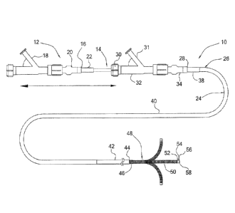
Turning to a first embodiment and with reference to Figure 1 a bi-directional
coaxial deflectable microcatheter is illustrated and designated generally by
reference
numeral 10. The catheter 10 includes an inner catheter (member) 12, an outer
catheter
(member) 24 and a distal portion 48 with a deflectable tip.
The inner catheter 12, which extends through a lumen in outer catheter 24, is
composed of a catheter body that is constructed of a thin walled body or tube
14 that
extends between proximal end 16 and distal end 58 having an inner lumen with a
diameter in the range of about 0.001" inches to about 1.993" inches with a
preferred inner
diameter of about 0.017" inches. Coupled to the proximal end of inner catheter
body 14
is winged hub 20, which sits on a strain relief 22 which optionally can be
provided. The
winged hub (luer) 20 can be made of plastic. If desired, winged hub 20 can
also be fitted
with a rotating hemostatic valve (RHV) 18 to provide a channel into the inner
lumen of
inner catheter 12 for insertion of an accessory or fluid introduction through
the side arm.
8
CA 02890745 2015-05-06
WO 2014/074986
PCMJS2013/069435
Possible accessories may include by way of example: guidewires, coils,
fiberscopes,
forceps, video cameras, laser or electrohydraulic lithotripsy devices, and
illumination or
laser fibers. Other accessories can also be inserted through the channel.
Outer catheter 24 is composed of a catheter body that is constructed of a thin
walled body or tube 26 having an inner lumen that extends between proximal end
28 and
distal end 44 having an inner lumen with a diameter in the range of about
0.007" to about
1.999" with a preferred inner diameter of about 0.027". Outer catheter body 26
also
features a relatively stiff proximal section 40 that is joined to a relatively
flexible distal
section 42. Coupled to the proximal end of outer catheter body 26 is winged
hub (luer)
34, which sits on strain relief 38 which optionally can be provided. Attached
to winged
hub 20 is rotating hemostatic valve (MTV) 32 with end cap 30 and side arm 31.
End
(lock) cap 30 acts as the locking assembly for the deflectable catheter while
side arm 31
is used for introduction of fluids for lubrication and possibly visualization.
The
lubrication can facilitate relative movement of inner catheter 12 during the
procedure
which facilitates deflection by ensuring smoother relative movement of the
inner and
outer catheters. When cap 30 is fully opened, inner catheter 12 is free to
move axially
resulting in distal tip 48 deflection as described below. Cap 30 can be
tightened at any
point in the deflection process to clamp and hold inner catheter 12 in
position and thereby
lock the tip 48 in place.
Deflectable tip 48 of inner catheter 12 is covered with lateral support tube
50,
which overlies the column member described below. Support tube 50 is adhered
at its
proximal and distal ends 46 and 52, respectively, as shown in Figure 11 and
described
below. Preferably lateral support tube 50 is a helically wound flexible coil
with an
outside diameter in the range of about 0.008" to about 2.00" with a preferred
diameter of
about 0.034". The coil may be made from a polymer or metal material but the
preferred
material is platinum/iridium for radiopacity. Disposed distally of lateral
support tube 50
is marker band 54, which is adhered at end 56 to the distalmost end 58 of the
inner
catheter 10. The band 54 can be made from a polymer or metal, the preferred
material is
platinum/iridium for radiopacity.
9
CA 02890745 2015-05-06
WO 2014/074986
PCT/US2013/069435
Figures 2 and 2A illustrate one embodiment of inner catheter 12 of deflectable
catheter 10. The inner catheter 12 as discussed above includes a winged hub
20, which
sits on an optional strain relief 22 and optional RHV 18. Inner catheter 12
also includes
catheter body 14 which preferably has a stiff proximal section 60 made up of a
braid
reinforced polymer tube that has an outer diameter in the range of about
0.002" to about
1.994" with a preferred diameter of about 0.023" and a length that extends
between
proximal end 16 and distal end 62 in the range of about 0.5 inches to about 34
feet with a
preferred length around 110 cm. Proximal section 60 is coupled at a distal end
to a less
stiff distal tube 64 that can be made of a braid or coil reinforced polymer
but is preferably
made up of high density polyethylene (HDPE) that has an outer diameter in the
range of
about 0.002" to about 1.994" with a preferred diameter of about 0,022" and
length that
extends from a proximal end (adjacent distal end 62 of proximal section 60) to
distal end
68 in the range of about 0.5 inches to about 34 feet with a preferred length
around 45 cm.
The overall usable length for the combined proximal and distal sections has a
range of
about 0.5 inches to about 34 feet with a continuous inner diameter in the
range of about
0.001" to about 1.993" with a preferred useable length being approximately 150
cm and
with a preferred inner diameter of about 0.017". Inner catheter body 14
further includes
laser cut tube 76, with window 74, which is coupled to distal tube 64 at its
distal end 70.
Laser cut tube 76 can be made of plastic or metal but is preferably made of
super elastic
nitinol with an inner diameter in the range of about 0.001" to about 1.993"
with a
preferred diameter of about 0.017". The outer diameter for laser cut tube 76
can range
from about 0.002" to about 1994", with a
preferred outer diameter of about 0.022". The
length of the laser cut tube can range from about 0.5 inches to about 34 feet
with a
preferred length of approximately 1 cm.
Distal portion 66 of inner catheter body 14 includes laser cut tube 76 that is
coupled to distal tube 64 using a tube 78, which is preferably a polyimide
tube coated
with adhesive 72. Preferably polyimide tube 78 has an inner diameter in the
range of
about 0.001" to about 1.993" with a preferred inner diameter of about 0.0165".
The outer
diameter of polyimide tube 78 can range from about 0.002" to about 1.994" with
a
CA 02890745 2015-05-06
WO 2014/074986
PCMJS2013/069435
preferred diameter of about 0.0175". Preferably, the length of polyimide tube
78 can
range between about 0.25 mm and about 1 cm with a preferred length of
approximately 3
mm.
The overall useable length of the inner catheter 12, which ranges from about
0.5
inches to about 34 feet, need not have separate materials for all of the
sections (proximal,
distal, and laser cut tube) described above. For instance, a laser cut nitinol
tube (or other
metal or plastic material such as polyimide) can have the necessary stiffness
variations
for the proximal and distal sections designed into it resulting in a suitable
inner catheter
body that meets the ranges for inner catheter 14.
Figure 3 illustrates an alternate embodiment of the inner catheter designated
by
reference numeral 312. In this embodiment, the inner catheter body 314 has a
lubricious
inner liner 82 that runs from proximal end 316 to distal end 358. The purpose
of the liner
is to help reduce the coefficient of friction to aid in guidewire movement
within the inner
catheter 314. The liner can be made of materials such as
polytetrafluoroethylene (PTFE)
.. or fluorinated ethylene propylene (FEY).
The liner 82 is topped with a combination of a continuous braid 84, coil 102,
and
laser cut tube 106 to help with lumen integrity (reinforcement) and to aid in
stiffness
variation. The braid 84, which can be made of flat or round wire or a
combination, runs
from proximal end 316 to distal end 398. The braid can be made of materials
such as
.. stainless steel, nitinol, polymer, fiber or even a combination of
materials. The coil 102,
which can be made of flat or round wire, runs from proximal end 398 to distal
end 104.
The coil 102 can be made of materials such as stainless steel, nitinol,
platinum/iridium or
even a polymer. The laser cut tube 106 runs from proximal end 104 just about
to distal
end 358. Laser cut tube 106 can be nitinol or other metal or it can be cut
from polyimide
as done by MicroLumen (Oldsmar, FL) or another polymer.
The reinforcement layer is topped with polymers with varying stiffnesses to
create
three distinct sections: proximal section 86, mid section 90, and distal
section 96.
Proximal section 86 extends distally from proximal end 316 to distal end 362.
Mid
section 90 extends distally from end 362 to distal end 94. Distal section 96
extends from
11
CA 02890745 2015-05-06
WO 2014/074986
PCMJS2013/069435
end 94 to distal end 358. The stiffness will decrease from proximal section 86
to distal
section 96. Reduction in stiffness can be achieved by using decreasing
durometers of
material from proximal to distal. Preferably, proximal section 86 can be
formed using
material 88 which can be a nylon or pebax having a durometer in the range of
60D to
75D or any other material having a relative durometer hardness value of around
72D, mid
section 90 can be formed using a lower hardness material 92 with a durometer
of around
63D, and distal section 96 can be formed with an even lower hardness material
100 such
as a pellethane material having a durometer of 25D to 5511 or other material
having a
durometer between 2511 and 4011 . These are just examples of materials and
durometers
that can be used. Also, each section does not need to be formed with a single
layer of
material, if desired, sections can be constructed of two or more layers.
Actual material
selection will be based On design needs for flexibility and
stiffnessõAdditional layers of
coils or braids may also be added as needed.
These layers are then fused together using a re-flow process (heat). Strain
relief
322 and winged hub 320 are then added. Lastly, the inner catheter may
optionally be
coated on its outer diameter for a length with a hydrophilic coating 108. The
purpose of
the coating is to aid in axial movement of the inner catheter relative to the
outer catheter
during the deflection process. If the coating requires hydration, liquid can
be injected
through the side arm 31 on RI-IV 32 attached to outer catheter 10 (see Figure
1).
As stated above, the typical microcatheter is formed using a re-flow technique
which fuses all of the layers together with heat and, if necessary removable
heat shrink
tubing. As the length of the inner catheter (or outer catheter) increases to
greater than
180 cm this may be a problem due to current equipment restrictions. An
alternate method
is to use non-removable heat shrink tubing of varying stiffnesses to create
the proximal,
mid, and distal sections. Also, although Figure 3 shows the braid 84, coil
102, and laser
cut tube 106 stopping or starting in either the proximal, mid, or distal
section, each of
those components can be made longer or shorter and as a result end or start at
points
different than shown.
12
CA 02890745 2015-05-06
WO 2014/074986
PCT/US2013/069435
Figure 4 illustrates another embodiment of the inner catheter designated
generally by reference number 312. Construction of inner catheter body 314' is
much the
same as that of Figure 3 with the exception of a longer, continuous coil 102'
for the laser
cut tube 106. A marker band 110 is provided. The marker band 110 may be made
of
platinum/iridium to aid in visualization under fluoroscopy or of other metals
or plastics.
The band 110 can also be made from a coil rather than a solid tube as shown or
even
omitted from the design. The remaining structure of the catheter is the same
as in Figure
3 and therefore identical reference numerals are used to identify identical
parts.
Another embodiment of the inner catheter is shown in Figure 5. In this
embodiment, the inner catheter body 412 is made from a single stainless steel
or nitinol
hypotube (or alternatively a plastic or polyimide) that has a laser cut spiral
section 116
that extends from proximal end 114 (adjacent distal section 415) to distal end
458. If
needed, the proximal end of the inner catheter body 414 can have texturing,
such as axial
knurling, contouring, or even additional layers or perpendicular features
added to aid in
pushing/pulling and locking. The catheter 412 includes strain relief 422 and
winged hub
420 at proximal 416. As in other embodiments, an optional outer shrink tubing
or
polymer layer and/or an inner lubricious layer can be added to the embodiment
of Figure
5 to restrict stretching or misalignment of the spiral coil due to axial
movement and
bending.
Turning now to the outer catheter structure of the microcatheter, and with
initial
reference to Figure 6, this Figure illustrates one embodiment of outer
catheter 24 of
deflectable catheter 10. In this embodiment, as noted above, outer catheter
body 26 has
RHV 32 with locking cap 30 and side arm 31 attached to winged hub 34. Winged
hub 34
sits on strain relief 38, both of which are coupled to catheter body 26.
Outer catheter body 26 has a lubricious liner 128 that runs from proximal end
28
to distal end 44 and has an inner diameter with a range of about 0.007" to
about 1.999"
and a preferred inner diameter of approximately 0.27". The purpose of the
liner 128 to is
aid in movement of the inner catheter during the deflection process by
reducing the
coefficient of friction between the outer catheter inner diameter and the
inner catheter
13
CA 02890745 2015-05-06
WO 2014/074986
PCMJS2013/069435
outer diameter. The liner can be made of materials such as
polytetrafluoroethylene
(PTFE) or fluorinated ethylene propylene (FEP).
The liner 128 is topped with a reinforcement layer of a continuous open pitch
coil
130 that runs from proximal end 28 to distal end 44. The coil 130 can be made
of flat or
round wire. The coil 130 can be made of materials such as stainless steel,
nitinol,
platinum/iridium or even a polymer or fiber. Also, the coil 130 need not be
open pitch or
a continuous length for the entire length of outer catheter body 26. For
instance, the
distal end may need to have a certain length of radiopacity and therefore
require a
platinum/iridium coil. To keep cost low, only the section requiring
radiopacity could be
platinum/iridium while the remainder of the body could be covered with a lower
cost
coil, such as a stainless steel version.
The reinforcement layer is topped with polymers with varying stiffnesses to
create
three distinct sections: proximal section 118, mid section 120, and distal
section 122.
Proximal section 118 extends distally from proximal end 28 to distal end 124.
Mid
section 120 extends distally from distal end 124 of proximal section 118 to
distal end
126. Distal section 122 extends from distal end 126 of mid section 120 to
distal end 44.
The stiffness will decrease from proximal section 118 to distal section 122.
Reduction in
stiffness can be achieved by using decreasing durometers of material from
proximal to
distal. For instance, proximal section 118 can be formed using material 132
which can be
a nylon or pebax having a durometer in the range of 60D to 75D or any other
material
having a relative durometer hardness value of around 72D, mid section 120 can
be
formed using a lower durometer material 134 with a durometer of around 63D,
and distal
section 122 can be formed with an even lower hardness material 136 such as a
pellethane
material having a durometer of 25D to 55D or other material having a durometer
between
25D and 40D. These are just examples of durometers that can be used, as actual
material
selection can be modified to optimize the balance of flexibility and
stiffness. The layers
that are selected are then fused together using heat. Alternatively, the
entire outer
catheter body can be made of a single durometer tube from materials such as
HDPE,
LDPE, nylon polyimide or polyurethane. A lubricious liner and reinforcement
coil or
14
CA 02890745 2015-05-06
WO 2014/074986
PCMJS2013/069435
braid may optionally be added to this tube as well. If needed, one or more
lumens (for
delivery or balloon inflation) can then be added in parallel along the length
of outer
catheter body 26 using adhesive or one or more heat shrink tubings, which may
or may
not be removed and may have differing durometers. The winged hub 34, strain
relief 38,
and RHV 32 with locking cap 30 and side arm 31 are then added.
The final useable length for outer catheter 26 can range from about 0.5 inches
to
about 34 feet with a preferable useable length of about 135 cm. The proximal
outer
diameter can range from about 0.008" (0.61 Fr) to about 2.00" (152 Fr) with a
preferred
proximal outer diameter of about 1 mm (3 Fr) and a preferred distal outer
diameter of
about 0.93 mm (2.8Fr).
Outer catheter body 26 further includes a marker band 138, which is inserted
mid
way into the inner diameter at the distal end of outer catheter body 26.
Preferably marker
band 138 has a length in the range of about 0.005" to about 1" with a
preferred length of
about 0.039" and an inner diameter in the range of about 0.0065" to about
1.9985" with a
preferred inner diameter of about 0.0265". The outer diameter has a range from
about
0.0075" to about 1.9995" with a preferred outer diameter of about 0.0285". The
marker
band 138 can be made of a metal or a polymer tube or coil with a preferred
material of
platinum/iridium.
The catheter 10 includes a column member e.g., a wire or tube, which extends
distally of the outer catheter 24, is attached to the inner catheter and is
surrounded by a
restriction (support) tube to restrict lateral movement of the column member.
In one
embodiment the column member includes a column 140, which at its proximal end
sits
on marker band 138 or alternatively in a slot cut along the length of the
marker band 138.
The proximal portion of column 140 is also inserted into the inner diameter,
i.e., the
catheter body wall, at the distal end of outer catheter body 26. Adhesive 146
is then
added to secure the parts in place. Preferably column 140 has a substantially
rectangular
cross section with a thickness in the range of about 0.0005" to about 0.5"
with a preferred
thickness of approximately about 0.002". The width can range from about
0.0005" to
about 1.95" with a preferred width of approximately about 0.005". The column
can have
CA 02890745 2015-05-06
WO 2014/074986
PCT/US2013/069435
a length that ranges from 0.25 mm to 10 cm with a preferred length of
approximately 8
mm. The column's preferred cross section is rectangular however other shapes
such as
oval can be used. A non-circular cross section is preferred to effect bending
in a desired
direction. In a preferred embodiment, the column is in the form of a
substantially
rectangular wire or flat ribbon to control the plane of deflection. Also, cuts
or other
features can be added to the column to influence movement. For example, the
spacing
and/or number of the cuts will effect movement as it will affect flexibility.
The thickness
of the walls and the dimensions will also affect flexibility and movement. The
column
can be made of any metal or metal alloy and even a plastic, however the
preferred
material is super elastic nitinol. Note the column 140 extends distally from
the outer
catheter distal end.
Distal portion 142 of outer catheter 24 includes distal end 44 having flare
144
(Figure 7) so that marker band 138 can be inserted approximately midway into
outer
catheter body 24 leaving a partial length exposed to create lip 148. Column
140 is then
inserted in between lubricious liner 128 and marker band 138 (which may or may
not
have a slot to accommodate the column) until its proximal end is approximately
flush
with the proximal end of marker band 138. Adhesive 146 is then applied to join
all of the
parts.
As an alternative to column 140 and marker band 138 being inserted as two
separate parts, the two can be made out of a single nitinol tube (laser cut)
if desired or
attached as a sub-assembly and then inserted. The band and column assembly may
also
be added during outer tube manufacture in which case marker band 138 would be
slid
over a lubricious liner.
An alternate embodiment of the outer catheter of deflectable catheter 10 is
illustrated in Figure 8 and designated by reference numeral 524. In this
embodiment, the
coil 110 has been replaced by a proximal hypotube 550 with a spiral cut that
is butted or
attached to the distal braid 552. Lengths for the parts may vary depending on
required
flexibility and stiffness needed for the part. The spiral cut hypotube 550 can
be
manufactured from stainless steel, nitinol, polymers or a combination.
Likewise, the
16
CA 02890745 2015-05-06
WO 2014/074986
PCMJS2013/069435
braid can also be manufactured from stainless steel, nitinol, a polymer, fiber
or a
combination. The remaining components of catheter 524 are identical to
catheter 24 of
Figure 6 and are therefore labeled with the same reference numerals.
By comparing Figures 2 through 8 it can be seen that the inner catheter body
14
and outer catheter body 526 can if desired be manufactured using the same
materials and
methods. Therefore, with the exception of lengths and diameters, it is
possible that both
structures can be built using a singular design or a mix of the designs
presented.
Figure 9 illustrates inner catheter 12 and outer catheter 24, with column 140
attached, aligned at distal portion 150. In manufacture, inner catheter 12 is
inserted into
outer catheter 24 until distal end 58 of laser cut tube 76 is flush with the
distal end of the
column 140. The laser cut tube 76 is then rotated until connectors or ribs 80
are about 90
degrees out of phase with the column 140 (and in a transverse plane and not
underneath
the column 140) to effect deflection in the desired plane. The distal end
alignment can be
done before or after rotation for orientation.
Inner catheter 12 and outer catheter 24 are aligned and joined together with
marker band 54 and adhesive or solder joint 56 at distal portion 150 (see
Figure 10).
Preferably marker band 54 has a length in the range of about 0005" to about 1"
with a
preferred length of about 0.039" and an inner diameter in the range of about
0.0065" to
about 1.9985" with a preferred inner diameter of about 0.0265". The outer
diameter has a
range from about 0.0075" to about 1.9995" with a preferred outer diameter of
about
0.0285". The marker band can be made of a metal or a polymer tube or coil with
a
preferred material of platinum/iridium. As one alternate construction, lip
148, column
140, and marker band 54 can all be made out of a single laser cut part made of
nitinol,
stainless steel or other suitable material. As another alternate construction,
column 140
can be soldered to marker band 138 and marker band 54 as a sub-assembly. In
another
alternate construction, column 140 and laser cut tube 76 can be joined
together at the
distal ends using a joint formed from solder, glue, laser (depending on
material), or other
joining process not requiring a band.
17
CA 02890745 2015-05-06
WO 2014/074986
PCMJS2013/069435
The preferred embodiment for alignment of the distal ends of column 140 and
the
inner catheter 12 (distal ends are approximately flush) is shown in Figure 10.
As an
alternative, outer catheter 24 with column 140 attached can be pulled back
proximally
along inner catheter 12 leaving a portion of the inner catheter body 14
exposed (without
column coverage). Marker band 54 can then be slid over the distal end of
catheter body
14, i.e., the tube 80, and then over column 140 until its distal edge aligns
with the distal
end of column 140. Joint 56 can then be formed. This set up will allow the
bend radius
of the device to remain at approximately half the column length while
decreasing the
crossing profile of the catheter distal tip to the inner catheter's outer
distal tip diameter.
Note adjustments may have to be made to the distal tubing 80 (i.e., the laser
cut tube) for
flexibility and coverage.
Figure 11 illustrates distal portion 150 with lateral support tube 50 in place
which
forms a cover for the column to provide the deflection method and system of
the
microcatheter. Preferably, lateral support tube 50 sits on lip 148 and is a
closed pitch
helically wound flexible coil made of platinum/iridium with an outer diameter
that ranges
from about 0.008" to about 2.00" with a preferred outer diameter of about
0.034" and an
inner diameter that ranges from about 0.007" to about 1.999" with a preferred
inner
diameter of approximately about 0.030". The preferred length can range from
about 1
mm to about 12 cm with a preferred length of approximately 6.5 mm. The coil
may be
made of any metal or plastic and may also be open pitched or a combination of
open and
closed pitch and optionally coated in plastic to form a solid flexible
reinforced tube. The
lateral tube support (cover) 50 can also be made of a solid tube, that may or
may not be
laser cut, from plastic materials such as HDPE, LDPE, CFlex, latex, silicone,
pebax,
nylon, polyurethane or polyisoprene. If solid tubes are used, drainage holes
can be
introduced on the lateral support tube or even outer catheter body to allow
fluid
introduced through side arm 31 to exit. The distal portion 150 further
includes two joints
46 and 52 that adhere lateral support tube 50 in place. As alternate options,
lateral
support tube 50 can be made to cover marker band 54 at its distal end or to
extend past lip
18
CA 02890745 2015-05-06
WO 2014/074986
PCT/US2013/069435
148 on its proximal end so that it sits directly on outer body 26 of outer
catheter 24 or the
lateral support tube 50 can be laser cut into the distal end of the outer body
26.
The addition of the lateral support tube 50 and its joints completes the
deflectable
catheter assembly. At this point, the outer diameter of the catheter can be
hydrophilically
coated or, if needed, additional lumens (as discussed earlier) for
accessories, such as
video cameras, fibers optics, or inflatable balloons can be added to the outer
shaft. This
may be accomplished with adhesives and/or shrink tubing of varying durometers.
If
attachments are made, the hydrophilic coating would be applied as the final
step.
Figure 12A illustrates distal portion 150 with spiral cut tip 156 (similar to
the
spiral cut tube of Figure 5) on the end of inner catheter 12 under an axial
pull load in the
absence of the lateral support tube 50. When inner catheter body 14 is pulled
axially by
load 154 in the proximal direction, the internal structure will want to
shorten causing
column 140 to compress. Figure 12B illustrates the effect when the inner
catheter body
is pushed axially by load 155 in the distal direction in the absence of
lateral support tube
50. As shown, this applies a moment to the end of the column causing it to
bend. Note the
load 154 (or 155) required to cause column 140 to move can be increased or
decreased by
changing the dimensions e.g., cross sectional dimension of column 140. For
instance, a
stiff column formed for example by a larger cross sectional dimension will
require more
force to deform and therefore more force to deflect which can in certain
instances be
more advantageous such as providing more stability to the bent tip.
Figure 13A and 13C illustrate distal deflectable tip 48 under axial pull load
154
when lateral reinforcement (support) tube 50 is provided. With lateral support
tube 50 in
place and axial pull load 154 applied, column 140 can no longer axially
compress due to
the reinforcement of the column by tube 50. As a result, the entire distal
tip, including
main (guidewire) lumen, deflects. Note as column 50 cannot be compressed and
the tip
deflects it moves against the wall. As noted above, by varying the dimensions
(or
materials or cuts) of the underlying column 140, the load 154 to deflect the
distal tip can
be increased or decreased. However, if the column becomes too thin, the column
will
19
CA 02890745 2015-05-06
WO 2014/074986
PCT/US2013/069435
become unstable leading to multiple buckling points under load. This will
result in little
to no tip deflection.
Figures 13B and 13D illustrate the effect when the inner catheter body is
moved
axially by load 155 in the distal direction when lateral support tube 50 is
provided. As
shown, this bends the distal tip as in Figure 12B. Note column 50 moves
against the wall
of the tube 50.
Note the movement discussed above and shown in Figures 12A-13D is
movement of the inner catheter, proximally or distally, respectively, as
shown. The same
effect is achieved by movement distally or proximally, respectively, of the
outer catheter.
Movement of both the inner and outer catheters in the desired directions is
also
contemplated.
A rotation control member 158 for minimizing rotation between the inner
catheter
12 and outer catheter 24 can be provided as shown in Figure 14. Rotation
control
member 158 is fixedly attached to inner catheter body 14 with joint 170. Flat
section 168
on rotation control member 158 works with flat section 166, which is formed by
indentation 164 on outer catheter body 26, to control rotation or torquing of
the catheters
relative to one another. Rotation control member 158 further includes proximal
lip 160,
which acts as an axial stop when it comes in contact with shoulder 162 on
indentation
164. Rotation control member 158 is preferably made of stainless steel but any
metal or
plastic can be used. The length can have a range from about 1" to about 24
feet with a
preferable length around 100 cm. Multiple short rotation members can also be
used and
placed at various points along the outer diameter of inner catheter body 14.
Flat section
166 can also be fanned directly on a hypotube, which can double as the
proximal shaft
for inner catheter body 14.
The microcatheter can include a locking assembly 172 for manipulating and
locking the distal deflecting tip as shown in Figure 15. Engagement of button
174 allows
the inner catheter 12 to be pulled or pushed axially relative to the outer
catheter 24
resulting in deflection of the distal tip. Once a deflected shape is decided
upon, the
button is released to set the shape. The button can also be held in (locked)
so that the tip
CA 02890745 2015-05-06
WO 2014/074986
PCT/US2013/069435
can be reshaped freely with catheter advancement. Alternately, the outer
catheter 24 can
be moved relative to the inner catheter 12 while the button is engaged also
bringing about
deflection. If lubrication is needed between the inner catheter and outer
catheter to assist
movement of the inner catheter, fluids such as saline or contrast can be
injected through
side arm 176 of locking assembly 172. If no lubricant is needed, side arm 176
can be
excluded from the design.
An alternate locking assembly for microcatheter 178 is illustrated in Figure
16.
Locking assembly 172 is designed for manipulating and locking the distal
deflecting tip
and has a rotational control system 180 built in, Rotational control system
180 includes a
stainless steel hypotube 182 which overlies the inner catheter body and which
has been
flattened in a region to create distal stop 184 and proximal stop 186, and
ovalized or
flattened hypotube 188, which in turn is soldered to stainless steel hypotube
180 which
overlies tube 188 for fitting within the RI-IV housing. The flattened tubes
are provided to
prevent rotation. Glue 192 is used to lock the hypotube 180 assembly in place
inside the
housing. The locking assembly is slid over inner catheter body 194 and glued
in place.
A gap 196 is left distal of the hypotube 182 so that hypotube 182 can be
pushed distally
to cause deflection. Although the handle has been shown without a screw
assembly for
locking axial movement of the inner catheter, such an assembly can be added to
the
proximal handle, if desired.
In use, stainless steel hypotubc 182 will be allowed to move proximally and
distally axially until stops 184 and 186 are reached. Rotation will be
restricted due to
flattened region on hypotube 182 and ovalized hypotube 188 through which it
freely
moves. This rotational control concept can be used on deflectable
microcatheter designs
with a full length guidewire lumen or deflectable microcatheters with rapid
exchange
ports. In general, this rotational control design can be used on any design
that requires
pure axial movement with little or no rotation. In addition, although this
design uses
flattened hypotubes, the concept can be injection molded into parts such as
rotation
hemostasis valves (RHV) to quicken manufacturing.
21
CA 02890745 2015-05-06
WO 2014/074986
PCMJS2013/069435
Figure 17 illustrates a coaxial hi-directional microcatheter 198 with a rapid
exchange port 200. The purpose of the rapid exchange port is to allow a
guidewire to be
placed through the side of the inner lumen of the catheter for tracking. The
rapid
exchange port may be placed anywhere proximal of the deflecting section (D) of
the
catheter. The exact placement will depend on bending radius used for design.
In some
embodiments, the exchange port 200 may be 6 mm from the distal tip although
other
distances are also contemplated. Also, the length of the rapid exchange port
which can
be cut on the inner catheter may be longer in some embodiments than the cut on
the outer
catheter to accommodate deflection with guidewire in place. However, they can
also be
cut to the same length or the outer catheter can be cut longer than the inner.
Because the
inner and outer catheters move relative to one another, the rapid exchange
ports must also
be able to move relative to one another to accommodate deflection. If the
guidewire or
other device will not be deflected, the rapid exchange port can be placed in
deflection
section D.
This embodiment allows for introduction of other devices through the proximal
end of the device. Shown extending from REV 202 by way of example is an
electrohydraulic lithotripsy (EEL) device 204, as made by Northgate
Technologies, Inc.
(Illinois). Other possible devices for insertion may include biopsy probes,
guidewires or
laser fibers, for example.
Figures 18A and 18B illustrates an alternate embodiment of the distal tip
deflection mechanism 206. The design allows the inner shaft with attached
components
to rotate and deflect 360 degrees with respect to the outer catheter. This is
achieved by
not attaching the column to the outer catheter and thus the column does not
extend and
attach both catheters. A portion Li of the outer catheter 208, the outer coil
210, and band
212 have been removed in Figure 18A to show the internal construction. Column
214 is
attached to distal band 216 and proximal band 218, as in previous designs;
however, a
section of the column continues proximally where it passes under band 220
which would
be glued in place inside outer catheter 208. Attached at the proximal end of
the column is
22
CA 02890745 2015-05-06
WO 2014/074986
PCT/US2013/069435
stop 222. This configuration will allow the column to turn with the inner
catheter body
and attached components when it is torqued.
Figure 18B illustrates the distal tip deflection mechanism 206 with outer
catheter
208, distal outer coil 210 and band 212 in place and in use. The inner
catheter 224 can be
rotated causing the column, which is now part of the inner catheter, to rotate
which
allows 360 degree deflection because it can deflect in any plane. When the
outer catheter
208 is advanced or the inner catheter 224 retracted, the outer catheter 208
will make
contact with end 226 and further movement will cause the tip to deflect. If
the outer
catheter is pulled proximally or inner catheter 224 is advanced, stop 222
contacts the
outer catheter and continued movement will cause the catheter to deflect in
opposite
direction. (Movement of the inner catheter, back and forth, will also cause
deflection).
In some embodiments, a balloon 232, such as an angioplasty balloon, can be
provided on the deflectable microcatheter distal portion. In the embodiment of
Figure
19A, the balloon 232 is mounted proximal of deflecting distal tip 230. In the
embodiment
of Figure 19B, distal tip portion 234 of the deflectable microcatheter has
balloon 236
mounted distal of deflecting distal tip 238. Other possible options include
mounting the
balloon in the middle of the deflection zone or at the very distal end, for
example.
Note the dimensions and ranges provided herein are given by way example, it
being understood that other dimensions and ranges for the components described
herein
are also contemplated.
The deflection of the catheter of the present invention can be summarized as
follows. Bi-directional deflection of the distal tip of a coaxial
microcatheter can be
broken down into two distinct motions: axial pull deflection and axial push
deflection.
Axial pull deflection can be modeled as an eccentrically loaded column while
axial push
deflection can be modeled as an eccentrically loaded beam.
With respect to axial pull deflection, when no lateral support tube is present
on
the distal end of the catheter, the rectangular nitinol wire (or alternate
column member
structure such as a rod discussed above) is modeled as an unsupported
eccentrically
loaded column. This means that when the inner catheter is moved axially
proximally
23
CA 02890745 2015-05-06
WO 2014/074986
PCMJS2013/069435
with a force P in the proximal direction, the distal end of the column
(rectangular nitinol
wire) will want to move axially toward its proximal end, resulting in
compression
(buckling) of the nitinol wire. This is shown in Figure 12A which illustrates
movement
of the column 140 in absence of the lateral support tube to explain the tip
concept of the
present invention. With the lateral support tube (e.g., coil) provided, when
the inner
catheter is pulled axially with a force P in the proximal direction, the
column (e.g.,
rectangular nitinol wire) will attempt to compress (buckle) axially however it
will be
restricted by the lateral reinforcement (support), e.g., tube 50. Since the
tip can no longer
fail axially (in compression), it will fail laterally (deflect) (see Figures
13A and 13C). It
.. should be appreciated that axial proximal movement of the inner catheter is
discussed.
However, it should be appreciated that distal movement of the outer catheter
would
achieve the same effect. Therefore, as used herein, relative movement includes
movement
of the inner catheter with respect to the outer catheter, movement of the
outer catheter
with respect to the inner catheter, or movement of both in opposite directions
with respect
to each other.
With respect to axial push deflection, when no lateral support tube is present
on
the distal end of the catheter, the rectangular nitinol wire (or alternate
column member
structure such as a rod discussed above) is modeled as an eccentrically loaded
beam. This
means that when the inner shaft is pushed axially with a force P it will apply
a moment to
the end of the beam (e.g., rectangular nitinol wire), which causes it to bend.
This is
shown in Figure 12B, with the lateral support tube (e.g., coil) provided and
the inner
catheter is pushed axially with a force P in the distal direction, there will
be a moment
applied to the overall tip causing it to bend (deflect) as shown in Figure 13B
and Figure
13D. In this case, the addition of the coil does not change the action. It
should be
.. appreciated that axial distal movement of the inner catheter is discussed.
However, it
should be appreciated that proximal movement of the outer catheter would
achieve the
same effect. Therefore, as used herein, relative movement includes movement of
the
inner catheter with respect to the outer catheter, movement of the outer
catheter with
24
CA 02890745 2015-05-06
WO 2014/074986
PCMJS2013/069435
respect to the inner catheter, or movement of both in opposite directions with
respect the
each other.
Axial pushing and pulling can be considered in terms of an x-y axis. Axial
pushing and pulling will happen on the x axis and bending (deflection) will
end up at a
point (x,y). So for compression of the column, causing the tip to bend to y 1
position, the
distal end of the tip is traveling in the direction towards its proximal
end (-x2).
Thus, as can be appreciated, in the coaxial catheter arrangement of the
present
invention, deflection of the distal tip is achieved by an axial motion, rather
than a pulling
down on the distal tip as in prior art non-coaxial catheters. Thus, the
catheter itself is
being used to bend the distal tip as opposed to the prior art side by side
wire and catheter.
Viewed in another way, the bending is achieved not by pulling in the direction
of bending
but by an axial movement. The structure of the deflectable catheter of the
present
invention saves space to reduce the overall size (diameter) of the catheter to
provide a
reduced profile for insertion. It also provides space for fluid flow to
enhance deflection
(by enhancing relative movement of the inner and outer catheters) without
requiring an
increase in the size (diameter) of the catheter.
While the above description contains many specifics, those specifics should
not
be construed as limitations on the scope of the disclosure, but merely as
exemplifications
of preferred embodiments thereof. Those skilled in the art will envision many
other
possible variations that are within the scope and spirit of the disclosure as
defined by the
claims appended hereto.