Note: Descriptions are shown in the official language in which they were submitted.
CA 02890821 2016-06-16
COLLAPSIBLE INTERMODAL FLAT RACK
FIELD OF THE INVENTION
[0001] The present invention relates to shipping containers and, more
particularly, to a
collapsible intermodal flat rack.
BACKGROUND
[0002] The term "intermodal" refers to a manner of transporting cargo by way
of ships, semi-
trailer trucks and/or railways. Cargo containers used during intermodal
transport have been
standardized to facilitate international trade. Indeed, the cargo containers
must pass the
certification tests of the International Organization for Standardization
(ISO) for durability if
they are to be used for both domestic and international transport. The most
widely used ISO
classification of container is the 1 AA class. Such containers are 40 foot
long, 8 foot in wide and
8.5 foot high and have lifting and stacking points at the tops of their four
corners. As a result,
cargo handling and transport equipment, such as cranes, trucks, trailers,
railway cars, etc., have
been built to accept containers having such fitments.
[0003] The weight capacity of a cargo container is often limited by the weight
of the container
itself. In other words, if the container is made lighter, it may be used to
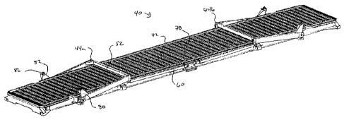
carry a heavier cargo
load. As a result, collapsible intermodal flat racks, such as the flat racks
offered by Domino
Flatracks (Clive-Smith Cowley Ltd) of the United Kingdom and illustrated in
published UK
Patent Application GB 2376014 and U.S. Patent No. 5,275,301, both to Clive-
Smith, have been
developed. Such collapsible intermodal flat racks omit the container side and
end walls and top
and instead feature a floor or cargo deck that features arches that are
pivotally attached to move
1
22936269 1
CA 02890821 2016-06-16
between an upright use position, a folded stored position and an expanded
position for placing a
load on the cargo deck from above (such as by crane).
[0004] In addition to offering a weight savings, such collapsible intermodal
flat racks permit the
cargo deck to be longer than 40 foot as the arches feature lifting and
stacking fitments and are
positioned inward from the flat rack ends and 40 foot apart to permit handing
by standardized
equipment.
[0005] In addition, the collapsible intermodal flat racks permit the flat
racks, when in the
collapsed storage configuration, to be stacked for transport. As a result, the
necessity of
returning an empty cargo container is avoided. Instead, a number of collapsed
intermodal flat
racks may be transported in the same space required to return a single empty
non-collapsible ISO
class IAA container.
[0006] While the collapsible intermodal flat racks of Clive-Smith offer the
above advantages,
changing the configuration of the arches or vertical uprights is laborious in
that they must be
directly lifted and handled and manually moved between the use, storage and
expanded load
positions. One solution to this problem is offered in U.S Patent No. 7,823,739
to Sadkin et al.,
where end walls of a collapsible shipping container are moved by a support or
lever on each side
having one end pivotally attached to the end wall, and a second end that moves
within a track
formed on the side of the cargo deck beam. A hydraulic or electric motor is
positioned under the
deck and moves the ends of the levers positioned within the tracks so that
they travel towards the
longitudinal center of the cargo deck thus causing the end walls to fold. The
disadvantage of this
approach, however, is that a source of power, either onboard or off, is
required. Furthermore, the
motor mechanism adds to the cost and complexity.
BRIEF DESCRIPTION OF THE DRAWINGS
[0007] Figs. IA-1C are perspective views of an embodiment of the collapsible
intermodal flat
rack of the present invention in the use, storage and expanded load
configurations, respectively;
[0008] Fig. 2 is a perspective view of a number of flat racks of the type
illustrated in Figs. 1A-
1C in a stacked configuration;
2
22936269.1
CA 02890821 2016-06-16
[0009] Fig. 3 is an enlarged perspective view of the stacking bocks and
stacking supports of Fig.
2;
[0010] Figs. 4A-4C are perspective views of an embodiment of the brace locking
assembly of
the present invention illustrating operation of the assembly;
[0011] Fig. 5 is a cross sectional perspective view of the brace locking
assembly of Fig. 4C;
[0012] Fig. 6 is a perspective view of the brace locking assembly of Fig. 4C
with the front plate
removed;
[0013] Fig. 7 is a perspective view of the brace locking assembly of Figs. 4A-
6 illustrating
further operation of the assembly;
[0014] Fig. 8 is a front perspective view of an embodiment of the crank
mechanism of the
present invention with the cargo deck floor removed;
[0015] Fig. 9 is a rear perspective view of the crank mechanism of Fig. 8;
[0016] Figs. 10A and 10B are cross sectional perspective views of the crank
mechanism of Figs.
8 and 9 with the fitment in extended and retracted positions, respectively;
[0017] Fig. 11 is a cross sectional perspective view of an embodiment of an
arch bearing
assembly on a side of the arch opposite a side featuring a crank mechanism;
[0018] Figs. 12A and 12B are cross sectional perspective views of the crank
mechanism
telescoping fitment assembly with the fitment in extended and retracted
positions, respectively;
[0019] Figs. 13A and 13B are enlarged cross sectional perspective views of the
proximal end of
the telescoping arm and related components of Figs. 12A and 12B, respectively;
[0020] Fig. 14 is a perspective view of a tool specifically adapted for
operation of the cranking
mechanism of Figs. 8-13B;
[0021] Figs. 15A and 15B are perspective views illustrating use of the tool of
Fig. 14;
3
22936269.1
CA 02890821 2016-06-16
[0022] Figs. 16A-16C illustrate use of the cranking mechanism of Figs. 8-13B
and the tool of
Fig 14;
[0023] Fig. 17 is bottom perspective view of the collapsible intermodal flat
rack of Fig. 1A;
[0024] Fig. 18 is a cross sectional perspective view of the flat rack of Fig.
17 taken along line
18-18 of Fig. 17;
[0025] Fig. 19 is an enlarged cross sectional perspective view of a portion of
the flat rack of Fig.
18;
[0026] Fig. 20 is a side elevational view of the collapsible intermodal flat
rack of Fig. 1B
[0027] Fig. 21 is a perspective view of a battery-powered tool for operation
of the cranking
mechanism of Figs. 8-13B.
DETAILED DESCRIPTION OF EMBODIMENTS
[0028] An embodiment of the collapsible intermodal flat rack of the present
invention is
indicated in general at 40 in Figs. 1A-1C. As illustrated in Fig. 1A, the flat
rack includes a cargo
deck, indicated in general at 42 upon which are positioned arches, indicated
in general at 44a and
44b. As will be explained in greater detail below, the arches are pivotally
attached to the cargo
deck. As illustrated for arch 44a, each arch includes a pair of upright posts
46 and 48 joined at
the top in a rigid fashion by top cross member 52. A pair of support braces 54
and 56 are
pivotally attached by their top ends to the arch 44a. The upright posts, top
cross member and
support braces are all preferably constructed from high strength steel, and
the upright posts and
top cross member preferably feature a hollow tube construction. As will be
explained in greater
detail below, the bottom ends of the support braces 54 and 56 travel in
channels 60 and 62. Arch
44b is provided with similar support braces and construction.
[0029] The arches 44a and 44b may be moved between the positions shown in
Figs. 1A-1C to
place the flat rack 40 in three configurations. More specifically, the arches
may be positioned so
that the flat rack is in a use or transport configuration, illustrated in Fig.
1A, a folded storage or
4
22936269.1
CA 02890821 2016-06-16
stacking configuration illustrated in Fig. 1B and an expanded top loading
configuration,
illustrated in Fig. IC.
[0030] The flat rack is placed in the use configuration of Fig. 1A when it is
loaded with cargo
and is to be transported by ship, truck or rail. As illustrated in Fig. 1A,
the top of upright posts
46 and 48 are provided with lifting fitments 64 and 66, respectively, while
arch 44b is provided
with lifting fitments 67 and 69. In addition, arch 44a pivots about axis 68,
while arch 44b pivots
about axis 70. Pivot axis 68 is located 20 feet from the longitudinal midpoint
72 of the cargo
deck 42 (the dimension indicated by arrow 74), while pivot axis 70 is located
20 feet from
midpoint 72 (arrow 76) in the opposite direction. As a result, lifting
fitments 64, 66, 67 and 69
are in the same position as the lifting fitments of a ISO class IAA shipping
container and may be
handled by the same lifting and transport equipment.
[0031] The flat rack is placed in the storage configuration illustrated in
Fig. 1B when it is no
longer loaded with cargo and it is desirable that the flat rack take up as
little room as possible for
storage and stacking. As illustrated in Fig. 1B, the top cross member 52 of
arch 44a and the top
cross member of arch 44b rest on the top surface of the floor 78 of the cargo
deck when the flat
rack is in the storage configuration.
[0032] As illustrated in Figs. 1A and 1B, arch 44a is provided with stacking
blocks 80 and 82
positioned at the bottom of the uprights posts 46 and 48, respectively. The
top of stacking block
80 is provide with a stacking pad 84, while the top of stacking block 82 is
provided with stacking
pad 86. The stacking pads may be flipped out of the way to expose lifting
fitments underneath.
Arch 44b is provided with similar stacking blocks. As illustrated in Figs. IA
and 1B, when
arches 44a and 44b are pivoted into the storage position, the stacking blocks
automatically pivot
up into a position where they may be used for stacking or lifting. With regard
to the latter, the
stacking blocks are positioned on the arches so that they are also 40 feet
apart and thus
correspond to the lifting fitment positions for ISO class IAA shipping
containers so that they
may be handled by the same lifting and transport equipment.
22936269.1
CA 02890821 2016-06-16
[0033] A number of stacked flat racks 40 are illustrated in Figs. 2 and 3. As
illustrated in Figs. 2
and 3, stacking supports 92 are positioned under or adjacent to the cargo deck
so as to be aligned
with and engaged by a raised stacking block of a neighboring (above or below)
flat rack.
[0034] With reference to Fig. 1C, the arches 44a and 44b may be tilted away
from the
longitudinal center of the flat rack so that cargo may be lowered from
overhead, such as by a
crane, and positioned on the floor 78 of the cargo deck 42. After such
loading, the arches 44a
and 44b may be returned to the use position of Fig. 1A.
[0035] As noted previously, with reference to Fig. 1A, the bottom ends of
support braces 54 and
56 are movably mounted within channels positioned on the sides of the cargo
deck 42. As
illustrated in Fig. 4A, the bottom end of the support brace 54 is provided
with a hook fitting 102
that includes a lock opening 104, a hook portion 106 and a roller tab 108. As
illustrated in Figs.
4A, 5 and 6, a generally C-shaped channel 60 is positioned on the side of the
cargo deck 42 and
features a downturned top lip 114. A roller 116 is rotationally attached to
roller tab 108 and rolls
within the channel 60. The top lip 114 keeps the roller 116 from traveling out
of the channel 60.
[0036] As illustrated in Figs. 1A-1C, the channel 60 runs nearly the entire
length of the side of
the cargo deck between the pivotal attachment locations of arches 44a and 44b.
As a result, the
roller 116 stays within the channel as the arch 44a moves between the storage,
use and expanded
load positions. This ensures that the bottom ends of the support braces are
secured during
transport and storage of the flat rack. Support brace 56 (Fig. 1A) and the
support braces of arch
44b operate in a similar manner.
[0037] As illustrated in Fig. 1A, the bottom end of support brace 54 is
secured in brace locking
assembly 120 when in the arch 44a is raised into the use position. The brace
locking assembly is
mounted on a main beam 122 of the cargo deck. Support brace 56 is provided
with a similar
brace locking assembly on the opposite side of the cargo deck (not visible),
while the bottom
ends of the support braces for arch 44b are also provided with similar brace
locking assemblies.
[0038] An enlarged view of a brace locking assembly is provided in Figs. 4A-5,
where it is
indicated in general at 120. The locking assembly includes a front plate 124
that includes pin
openings 126 and 128. Mounted behind the front plate 124 is a pin housing 132.
The pin
6
22936269.1
CA 02890821 2016-06-16
housing is shaped so that a gap 133 is formed behind the front plate. The back
side of the pin
housing 132 is mounted to cargo deck main beam 122. As illustrated in Fig. 5,
a stop pin 134
and a locking pin 136 are slidably mounted within the pin housing 132. As
illustrated in Fig. 4A,
the stop pin is provided with a handle 138 while the locking pin is provided
with a handle 140.
The pin housing 132 features elongated slots that accommodate the stop and
locking pin handles
as they protrude outside of the pin housing. As a result, they may be moved
between extended
positions, illustrated for both pins in Fig. 5, and retracted positions,
illustrated for both pins in
Fig. 7.
[0039] In use, when the arch 44a is moved from the storage position of Fig. 1B
towards the use
position illustrated in Fig. 1A, the hook fitting 102 of Fig. 4A travels
toward the brace locking
assembly 120, in the direction of arrow 142 (Fig. 4A). As illustrated in Fig.
4A, the locking
assembly is configured with the locking pin retracted, and the stop pin 134
extended so that it
passes through the pin opening 126 of the front plate 124. As illustrated in
Fig. 4B, the hook
portion of the hook fitting 102 travels into the slot 133 of the brace locking
assembly and
engages stop pin 134.
[0040] Next, as illustrated in Fig. 4B, lever 140 of the locking pin is pulled
towards the front
plate 124, as indicated by arrow 146. Before doing so, however, a pin lock 144
that is attached
by its top end to the side of the pin housing 132 by a hinge 152 is raised so
that the handle 140
may pass under it. As illustrated in Figs. 4C-6, the locking pin 136 then
passes through the lock
opening 104 of the hook fitting 102. The pin lock 144 is then lowered into the
position shown in
Fig. 4C. As a result, the lower end of the support brace 54 is locked in the
position illustrated in
Fig. 1A.
[0041] When it is desired to move arch 44a into the extended load position of
Fig. 1C, the stop
pin 134 is moved into the retracted position illustrated in Fig. 7 via stop
pin handle 138. The
handle 138 of the stop pin 134 is provided with a pin lock similar to pin lock
144 of the locking
pin handle 140. As a result, this pin lock must be raised and lowered as the
handle 138 is moved
from the stop pin extended position to the stop pin retracted position in the
manner described
above for the locking pin handle 140. The locking pin 136 is also retracted
via handle 140. With
7
22936269.1
CA 02890821 2016-06-16
the hook fitting 102 released from the brace locking assembly 120, the support
brace may travel
towards the end of the flat rack, in the direction of arrow 154 in Fig. '7.
[0042] As illustrated in Fig. 8, a sleeve 164 (also illustrated in Figs. 1A
and 9) receives the
bottom end of upright post 46.
[0043] As also illustrated in Fig. 8, a bearing box 168 is secured to the
outer side surface of main
beam 122 of the cargo deck. As illustrated in Figs. 10A and 10B, the bearing
box 168 is
positioned under the floor 78 of the cargo deck and under channel 60. The
bearing box houses
and supports in a fixed fashion an outer bearing tube 172 (Figs. 9, 10A and
10B), which is also
connected to main beam 122. An inner bearing tube 174 is secured to the sleeve
164 in a fixed
manner. The inner bearing tube 174 is received within the outer bearing tube
so that the that the
upright post 46 is supported by its bottom end to the cargo deck in a pivoting
fashion.
[0044] Upright post 48 (Fig. 1A) also features a bottom end that is received
within a sleeve 176,
as illustrated in Fig. 11. An inner bearing tube 178 is attached to the sleeve
176 in a fixed
fashion. An outer bearing tube 182 is housed and supported in a fixed fashion
within a bearing
box 184. The bearing box 184 is attached to a second main beam member 186 of
the cargo deck
(discussed in greater detail below) and is positioned under the floor 78 of
the cargo deck and a
channel 62 that receives a roller mounted on the bottom end of support brace
56 of Fig. 1A (in
the same manner as channel 60 for support brace 54). As a result, upright post
48 is supported
by its bottom end to the cargo deck in a pivoting fashion.
[0045] A crank mechanism for raising and lowering arch 44a (Fig. 1A) so that
it may be moved
between the use, storage and extended load positions illustrated in Figs. 1A-
1C is indicated in
general at 192 in Figs. 8 and 9. Arch 44b is provided with a similar
mechanism. As illustrated
in Figs. 8, 9, 10A and 10B, the crank mechanism includes a gearbox 194, a
brake 196, a gearbox
input shaft 202 and a tubular gearbox output shaft 204. These components are
positioned under
the floor of the cargo deck so that they are protected from weather and
damage.
[0046] As illustrated in Figs. 9, 10A and 10B, the gearbox output shaft 204
passes through an
opening formed through the end wall of the outer bearing tube 172 and is
secured to the inner
bearing tube 174.
8
22936269.1
CA 02890821 2016-06-16
[0047] The crank mechanism 192 also includes a crank mechanism fitment 206,
showed with the
fitment 206 in the extended position in Figs. 8 and 10A, and in the retracted
position in Fig. 10B.
The fitment passes through an opening 208 formed in the middle of the inner
bearing tube 174.
[0048] Enlarged views of the telescoping fitment are provided in Figs. 12A,
12B, 13A and 13B.
The crank mechanism fitment 206 is provided with tool holes 210. As
illustrated in Figs. 12A
and 12B, the fitment also includes an end opening 212 provided with an annular
flange 214. The
crank mechanism fitment 206 is mounted to the end of a telescoping arm 220
which is tubular
and preferably features a square cross section. The gearbox input shaft 202
has a square cross
section and is sized to be received in a sliding fashion within the
telescoping arm 220. A guide
pin 222 is secured to the input shaft 202 and is received within a guide slot
224 formed within
the telescoping arm 220. As a result, the guide pin traverses the guide slot
224 as the fitment
206, and thus telescoping arm 220, are moved between the extended position
illustrated in Fig.
12A (corresponding to Figs. 8 and 10A) and the retracted position illustrated
in Fig. 12B
(corresponding to Fig. 10B).
[0049] As illustrated in Fig. 12A and 13B, the telescoping arm 220 has a pair
of retracted
position locking holes 226 and, as illustrated in Figs. 13A and 13B, a pair of
extended position
locking holes 228. As illustrated in Figs. 13A and 13B, the gearbox input
shaft 202 includes
bore within which is position a spring 232 and a pair of spring balls 234. The
spring is a
compression spring and thus urges the spring balls outward. As illustrated in
Fig. 13A, when the
fitment and the telescoping arm are in the extended position (Fig. 12A), the
spring balls 234
engage extended position locking holes 228 of the telescoping arm 220 to
secure the fitment 206
in the extended position illustrated in Figs. 8 and 10A. Conversely, as
illustrated in Fig. 13B,
when the fitment and telescoping arm are in the retracted position (Fig. 12B),
the spring balls
234 engage retracted position locking holes 226 of the telescoping arm 220 to
secure the fitment
206 in the retracted position (Fig. 10B).
[0050] The operation of the crank mechanism of Figs. 8-13B for raising and
lowering the arch
44a (Fig. 1A) will now be explained with reference to Figs. 14-16C. While a
number of
alternative tools may be used to operate the crank mechanism, including a
conventional winch
bar, a tool specifically adapted for use with the mechanism, such as the one
indicated in general
9
22936269.1
CA 02890821 2016-06-16
at 240 in Fig. 14 is preferred. As illustrated in Fig. 14, the tool includes
an elongated body 244
having an angled pick 246 with a tapered diameter at a first end. A
circumferential bead 248 is
formed around the tip of the pick, the purpose of which will be explained
below. A handle 252
is attached to the elongated body 244 in a generally perpendicular fashion. A
reduced diameter
portion 254 is positioned on a second end of the tool and is provided with a
spring ball 256
(having a construction similar to the spring ball 234 and spring 232 of Figs.
13A and 13B, but
only with one spring ball 256). An angled guide 258 is also attached to the
second end of the
tool and passes over the reduced diameter portion 254.
[0051] As illustrated in Fig. 15A, the fitment 206 is pulled out from the
retracted stored position
within the inner bearing tube 174 by inserting the pick end 246 of the tool
240 into the open end
of the fitment and engaging the annular flange 214 with circumferential bead
248 (Fig. 14). The
fitment is then pulled out into the extended position for use in actuating the
mechanism (192 of
Figs. 8-10B).
[0052] Next, as illustrated in Fig. 15B, the reduced diameter portion 254 on
the second end of
the tool 240 is inserted into a corresponding pair of the tool holes 210 of
fitment 206. The spring
ball 256 (Fig. 14) and the angled guide 258 ensure that the tool remains
engaged with the fitment
as the tool, and thus the fitment, are turned via handle 252. In addition, the
angled guide ensures
that the handle 252 of the tool remains pointed outwards to facilitate turning
the crank
mechanism.
[0053] With reference to Fig. 16A, the flat rack 40, in the storage
configuration, is positioned on
a railcar or a trailer of a semi-trailer truck, indicated in phantom at 260. A
user then grasps the
handle 252 of the tool 240 and rotates it in the direction of arrow 262.
[0054] With reference to Figs. 10A and 12A, this causes the fitment 206, the
telescoping arm
220 and the gearbox input shaft 202 to turn as a unit. The gearbox 194 (Figs.
9 and 10A) then
transfers the rotational force, with a mechanical advantage, to the gearbox
output shaft 204,
which in turn pivots inner bearing tube 174 and upright post 46 via sleeve
164. As a result, the
arch 44a rises as indicated by arrow 264 (Fig. 16A) into the use position
illustrated in Fig. 16B.
22936269.1
CA 02890821 2016-06-16
[0055] Gearboxes suitable for use as gearbox 194 are well known in the art and
may find use, for
example, in the robotics industry. As an example only, a suitable gearbox is
the Model No.
RV320 gearbox available from the Nabtesco Corporation of Japan.
[0056] As indicated at 196 in Figs. 8, 9 and 10A, the gearbox input shaft 202
is coupled to the
gearbox 194 by brake 196. The brake 196, which is preferably a Weston brake,
prevents the arch
44a from crashing down to the cargo deck 42 in the event that the handle of
the tool 240 is
released, or the tool becomes disengaged from the fitment 206, when the arch
44a is midway
between the storage and use positions illustrated in Figs. 16A and 16B. In
addition, the brake
196 permits the arch 44a to be lowered to the cargo deck in a controlled
fashion when the handle
240 is turned in the direction of arrow 266 of Fig. 16B. Arch 44b (Fig. 1A) is
provided with a
similar crank mechanism and functionality.
[0057] If the tool 240 is turned in the direction of arrow 262 of Fig. 16A
when the arch 44a is in
the position of Fig. 16B, the arch moves into the expanded load position
illustrated in Fig. 16C.
The braking action of the brake 196 (Figs. 8, 9 and 10A) may only operate on
the motion of the
arch moving between the storage and use positions (Figs. 16A and 16B).
Nevertheless, when the
arch 44a travels from the use position illustrated in Fig. 16B to the expanded
load position
illustrated in Fig. 16C, the gearbox has enough resistance to lower the arch
in a controlled
manner until the stacking blocks 80 contact corresponding stacking supports
90, which serve as
stops. The stacking block and corresponding stacking support are illustrated
at 80 and 92,
respectively, in Fig. 16C for upright post 46. Upright post 48 of Fig. 1A and
the upright posts of
arch 44b are also provided with stacking blocks and corresponding stacking
supports and operate
as stops in the same manner.
[0058] With reference to Fig. 1A, as described above, the lower end of upright
post 46 is
pivotally attached to the cargo deck with a crank mechanism to raise and lower
the arch 44a,
while the lower end of upright post 48 is merely pivotally attached by way of
a bearing
arrangement. As a result, upright post 46 has a natural tendency to lead
upright post 48 as the
arch 44a is raised from the storage position into the use position. This would
make locking the
lower end of support brace 56 into its corresponding brace locking assembly
difficult. To
address this issue, arch 44a is preferably constructed to include a slight
counterclockwise
11
22936269.1
CA 02890821 2016-06-16
(looking down) twist with respect to axis 268 of Fig. 1A so that upright post
48 leads upright
post 46 in the direction of arrow 270 (Fig. 1A) as the arch is moved from the
storage to the use
position. This causes the bottom end of support brace 56 to reach its
corresponding brace
locking assembly prior to brace 54. The bottom end of brace 54 may then be
pulled into its
corresponding brace locking assembly (120 In Figs. 4A-7) as the crank
mechanism is actuated to
move the arch 44a into the upright position. Arch 44b features a similar
construction and
operation.
[0059] The construction of the cargo deck 42 is best illustrated in Figs. 17-
19. The cargo deck
features a pair of main beams 122 and 186 which are joined by a number of
cross beams, such as
cross beam 272. The main beams and cross beams are preferably constructed from
steel,
although aluminum may be used for some of the beams as a lighter alternative.
The floor 78 of
the cargo deck is bordered on each side by channels 60 and 62 (Figs. 11 and
18). As illustrated
in Figs. 17-19, the floor 78 is made up of a number of hollow plank members
274 that are
preferably aluminum and joined or formed in a side-by-side configuration to
form a unitary
aluminum construction, such as that of the REVOLUTION flatbed trailer from the
Fontaine
Trailer Company of Haleyville, Alabama. In addition, a steel box 280 serves as
one of the cross
beams near an end of the flat rack. As illustrated in Fig. 17, a door 282
formed in the main beam
122 provides access to the interior of the box 280 so that tools and other
items may be stored.
[0060] The flat rack floor 78 may be provided with channels for receiving
sliding load securing
brackets, as illustrated in commonly assigned U.S. Patent Nos. 7,571,953 and
8,057,143. In
addition, the channels 60 (Fig. 17) and 62 (Fig. 19) may be incorporated into
the flat rack cargo
deck via a one-piece side rail as illustrated in commonly owned U.S. Patent
Nos. 7,588,754 and
7,896,427.
[0061] As illustrated in Fig. 20, the cargo deck 42 preferably features three
zones including a
central zone, indicated by arrow 300, flanked by end zones 302 and 304.
Central zone 300
features a flat top surface 306 of floor 78 while end zones 302 and 304 each
feature top surfaces
307 and 308, respectively, that taper down from the flat top surface 306 to
opposite ends of the
flat rack. Main beams 122 and 186 include top profiles to accommodate these
three zones. The
12
22936269.1
CA 02890821 2016-06-16
flat central zone 300 provides the advantage of a level surface to support
oversized loads, such as
the load indicated in phantom at 310 in Fig. 20, which must be loaded from
overhead with arches
44a and 44b in the expanded load positions illustrated. More specifically, by
provided a flat
support surface under the majority of the load 310, there is no "teeter-
totter" effect on the load,
which increases load stability. The tapered end zones 302 and 304 provide a
reduction of
material and weight savings.
[0062] As an example only, central zone 300 may have a length of approximately
27.5 feet, with
each end zone 302 and 304 having a length of approximately 12.75 feet long.
This would be, for
example, for a flat rack having a height of 9.5 feet (when in the use position
illustrated in Fig.
1A), a width of 8.5 feet (to match the dimensions of a domestic container) and
a length of 53
feet.
[0063] A battery-powered tool for operating the cranking mechanism is
indicated in general at
400 in Fig. 21. As illustrated in Fig. 21, the battery-powered tool features a
housing 402 which
contains the tool's battery and motor. The battery powers the motor which
turns socket or sleeve
404. Socket 404 is sized to receive the crank mechanism fitment 206 (Figs. 15A
and 15B). The
socket features an aligned pair of pin holes 408a and 408b. In use, a pair of
the tool holes (210
in Figs. 15A and 15B) of the crank mechanism fitment are aligned with the pin
holes 408a and
408b when the fitment 206 is positioned within the socket 404. A locking pin
410 is then
inserted through the pin holes of the socket 404 and the tool holes 210 of the
crank mechanism
fitment so that the fitment is locked within the socket. The user, while
grasping handle 412 of
the battery-powered tool, squeezes trigger 414 so that the tool motor is
activated and the socket
404 is turned so as to turn the cranking mechanism to raise and lower the
arches (44a and 44b of
Fig. 20) of the intermodal flat rack. The tool features a guard 416, having an
opening 418
corresponding to socket 404, to prevent accidental contact with the turning
socket 404.
[0064] While the preferred embodiments of the invention have been shown and
described, it will
be apparent to those skilled in the art that changes and modifications may be
made consistent
with the principles described herein.
13
22936269.1