Note: Descriptions are shown in the official language in which they were submitted.
- 1 -
Multi-level furnace and method for thermal treatment of a
material flow
The invention relates to a multi-level furnace and to a method
for the thermal treatment of a material flow, preferably a
material flow containing carbon.
The thermal treatment of a material flow is understood as also
meaning in particular a torrefaction, in which biomass is
thermally treated by pyrolytic decomposition at relatively low
temperatures of 250 to 450 C with the exclusion of air.
WO 2012/007574 Al discloses a device and a method for the
drying and torrefaction of at least one carbon-containing
material flow in a multi-level furnace. The drying and the
torrefaction take place there in two different process
chambers that are spatially separate from one another. This
spatial separation makes it possible for the atmosphere to be
specifically set to suit the respective process (drying or
torrefaction). In this way, the efficiency, and consequently
also the throughput, of the device can be increased
significantly. The transfer device provided between the two
process chambers is not specified any more precisely in this
document. It is however conceivable to realize the gas
separation of the process chambers by cellular wheel sluices
or double swing valves. However, the installation of these
sluices is only possible outside the process chambers, and so
a separate furnace is required for each process chamber.
The invention is therefore based on the object of reducing the
structural complexity of the gastight separation of the two
process chambers.
The multi-level furnace according to the invention for the
thermal treatment of a material flow, preferably a material
CA 2891488 2019-04-02
- 2 -
flow containing carbon, has at least two process chambers
arranged one above the other, which respectively provide at
least two floors for the levels, and is equipped with one or
more transfer devices for transferring the treated material
flow from an upper process chamber to a lower process chamber,
the transfer device having for the gastight separation of the
two process chambers means for forming a column of material in
the transitional region between the upper process chamber and
the lower process chamber, the means for forming a column of
material comprising at least one delivery unit or at least one
chute or a slider and the at least one delivery unit or at
least one chute at the same time forming a material output
device for the upper process chamber and/or a material input
device for the lower process chamber.
In the case of the method according to the invention for the
thermal treatment of a material flow, preferably a material
flow containing carbon, this material flow is treated in a
multi-level furnace in at least two process chambers arranged
one above the other and separated gastightly from one another
and respectively equipped with at least two floors for the
levels. The material flow is transferred by a transfer device
from an upper process chamber to a lower process chamber, a
column of material being formed in the transfer device for the
gastight separation of the two process chambers, the forming
of the column of material being performed by at least one
delivery unit or at least one chute or a slider and the at
least one transfer device being used not only for transferring
the material flow from the upper process chamber to the lower
process chamber but also for discharging at least part of the
material flow from the multi-level furnace and/or for
introducing material into the multi-level furnace from
outside.
CA 2891488 2019-04-02
- 3 -
Using the material to be treated to ensure the gastight
separation of the two process chambers can be realized in a
structurally comparatively simple manner. The further
advantage is especially also that the transfer device can be
realized within the multi-level furnace.
The fact that the at least one delivery unit at the same time
forms a material output device for the upper process chamber
and/or a material input device for the lower process chamber
gives rise to the possibility of being able to discharge
partly treated material or feed in additional material while
bypassing an upper process chamber.
In this case, at least three process chambers arranged one
above the other and at least two delivery units may be
provided, the two delivery units being connected to one
another in such a way that at least one process chamber
arranged between the two delivery units is bypassed. It is
also conceivable that one or both delivery units is/are in
connection with at least one material store and/or
intermediate store.
According to a preferred refinement of the delivery unit, it
has a first feed opening, in connection with the upper process
chamber, and a first outlet opening, provided at an end region
of the delivery unit and in connection with the lower process
chamber. Furthermore, a second feeding device may be provided,
connected to a material charge, for directly charging filter
dust, reject materials, odor-intensive materials or materials
for increasing the reactivity or the delivery capacity into
the lower process chamber. Furthermore, the delivery unit may
also have a second outlet opening, in connection with the area
outside the multi-level furnace, for discharging material from
the multi-level furnace. The delivery unit or units is/are
therefore appropriately equipped with a reversible drive, in
CA 2891488 2019-04-02
- 4 -
order to connect the feed opening to the first or second
outlet opening in terms of delivery.
Instead of a delivery unit, according to another exemplary
embodiment of the invention the means for forming a column of
material may also comprise a chute in which a column of
material forms.
For monitoring the gastight separation of the two process
chambers, according to a further aspect of the invention it is
provided that the differential pressure between the upper
process chamber and the lower process chamber is determined.
Then there is also the possibility that the delivery rate of
the at least one delivery unit is controlled in dependence on
the measured differential pressure in such a way that a
gastight separation of the two process chambers is ensured.
This gastight separation of the process chambers makes it
possible that the temperature and/or the humidity and/or the
pressure in the two process chambers can be set individually.
The thermal treatment of the material flow in the individual
process chambers in this case preferably takes place with the
aid of a stream of treatment gas, which is fed to each process
chamber and, after acting on the material flow, is removed
again. The gastight separation of process chambers lying one
above the other provides the possibility of individually
setting the direction of flow of the treatment gas with
respect to the direction of the material flow, the direction
of flow of the treatment gas preferably being set in co-flow
in at least one upper process chamber and in counter-flow in
at least one lower process chamber. The co-flow treatment is
of advantage in particular for the drying of the material
flow, while the torrefaction appropriately takes place in
counter-flow.
CA 2891488 2019-04-02
- 5 -
In an aspect of the present disclosure, there is provided a
multi-level furnace for the thermal treatment of a material
flow (25) with
a. at least two process chambers (1-4) arranged one above
the other, which respectively have at least two floors
for the levels (5-11), and
b. one or more transfer devices (21-24) for transferring
the treated material flow from an upper process chamber
(1) to a lower process chamber, the two process chambers
(1, 2) being gastightly separated from one another,
characterized in that the transfer device (21-24) has for
the gastight separation of the two process chambers means for
forming a column of material (26) in the transitional region
between the upper process chamber (1) and the lower process
chamber (2), the means for forming a column of material
comprising at least one delivery unit (21.1) or at least one
chute (24.1) and the at least one delivery unit (21.1) or at
least one chute (24.1) or a slider at the same time forming a
material output device for the upper process chamber (1)
and/or a material input device for the lower process chamber
(2).
In an embodiment of the present disclosure, there is provided
a multi-level furnace characterized in that at least three
process chambers (1-4) arranged one above the other and at
least two delivery units (21-23) are provided, the two
delivery units being connected to one another in such a way
that at least one process chamber arranged between the two
delivery units is bypassed.
In another embodiment, there is provided a multi-level furnace
characterized in that the at least two delivery units (22, 23)
are in connection with at least one material store (33) and/or
intermediate store.
CA 2891488 2019-04-02
- 6 -
In another embodiment, there is provided a multi-level furnace
characterized in that the at least one delivery unit (21.1)
has a first feed opening (21.2), in connection with the upper
process chamber, and a first outlet opening (21.4), provided
at an end region of the delivery unit and in connection with
the lower process chamber.
In another embodiment, there is provided a multi-layer furnace
characterized in that the at least one delivery unit (21.1)
has furthermore a second feed opening (21.6), connected to a
material charge, for directly charging filter dust, reject
materials, odor-intensive materials or materials for
increasing the reactivity or the delivery capacity into the
lower process chamber (2).
In another embodiment, there is provided a multi-level furnace
characterized in that the at least one delivery unit (21.1)
has furthermore a second outlet opening (21.5), in connection
with the area outside the multi-level furnace, for discharging
material from the multi-level furnace.
In another embodiment, there is provided a multi-level furnace
characterized in that the at least one delivery unit (21.1)
has a reversible drive, in order to connect the first feed
opening (21.2) to the first or second outlet opening in terms
of delivery.
In another embodiment, there is provided a multi-level furnace
characterized in that the means for forming a column of
material comprise at least one chute.
In another aspect, there is provided a method for the thermal
treatment of a material flow (25) in a multi-level furnace,
the material flow being treated in at least two process
chambers (1-4) arranged one above the other and separated
CA 2891488 2019-04-02
- 7 -
gastightly from one another and respectively equipped with at
least two floors for the levels (5-11), and the material flow
being transferred by a transfer device (21-24) from an upper
process chamber to a lower process chamber,
characterized in that a column of material (26) is formed
in the transfer device (21-24) for the gastight separation of
the two process chambers (1-4), the forming of the column of
material (26) being performed by at least one delivery unit
(21.1) or at least one chute (24.1) or a slider and the at
least one transfer device (21-23) being used not only for
transferring the material flow from the upper process chamber
to the lower process chamber (1-4) but also for discharging at
least part of the material flow (25) from the multi-level
furnace and/or for introducing material into the multi-level
furnace from outside.
In another embodiment, there is provided a method
characterized in that the differential pressure between the
upper process chamber and the lower process chamber (1-4) is
determined, in order to monitor the gastight separation of the
two process chambers (1-4).
In another embodiment, there is provided a method
characterized in that the temperature and/or the humidity
and/or the pressure and/or the atmosphere in the at least two
process chambers (1-4) can be set individually.
In another embodiment, there is provided a method
characterized in that the delivery rate of the at least one
delivery unit (21.1) is controlled in dependence on the
measured differential pressure in such a way that a gastight
separation of the two process chambers (1-4) is ensured.
In another embodiment, there is provided a method
characterized in that the material flow (25) is treated in at
CA 2891488 2019-04-02
- 8 -
least three process chambers (1-4) gastightly separated from
one another, part of the material flow being fed from an upper
process chamber to a lower process chamber while bypassing a
middle process chamber.
In another embodiment, there is provided a method
characterized in that each process chamber is fed at least one
stream of treatment gas (14, 19, 31, 32), which after acting
on the material flow (25) is removed again.
In another embodiment, there is provided a method
characterized in that the direction of flow of the treatment
gas (14, 19, 31, 32) with respect to the direction of material
flow is set individually in the at least two process chambers
(1-4).
Further refinements of the invention are explained more
precisely below on the basis of the description of a number of
exemplary embodiments and the drawing, in which:
Figure 1 shows a schematic representation of a multi-level
furnace according to a first exemplary embodiment,
Figure 2 shows a schematic view of a detail of the transfer
device formed as a delivery unit,
Figure 3 shows a schematic representation of a multi-level
furnace according to a second exemplary embodiment
and
Figure 4 shows a schematic representation of a multi-level
furnace according to a third exemplary embodiment.
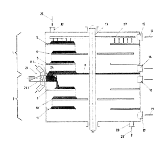
The multi-level furnace represented in Figure 1 for the
thermal treatment of a material flow serves for example for
CA 2891488 2019-04-02
- 9 -
the drying and torrefaction of a material flow containing
carbon. It has two process chambers 1, 2, which are arranged
one above the other and respectively have multiple floors for
the levels 5 to 11. The material flow 25 to be treated is fed
to the process chamber 1 from above by way of a feeding device
12. The transporting of the material on the floors for the
levels takes place by way of customary transporting devices,
such as for example a rabble arm system 27 rotating with a
central column 13, which transport the material to inner- or
outer-lying openings, where the material falls onto the floor
for the next-lower level. It is of course also conceivable in
principle that the floors for the levels rotate with the
central column 13 and interact with fixed strippers. In Figure
1, only one rabble arm system 27 is represented in the region
of the floor for the level 5. It goes without saying that such
rabble arm systems may also be provided in the region of the
floors for the other levels.
The heat treatment of the material flow 25 in the upper
process chamber 1 takes place with the aid of a first stream
of treatment gas 14, which is fed in by way of an input 15,
provided in the upper region of the process chamber 1, and is
removed by way of an output 16, provided in the lower region
of the process chamber 1. In the case of this arrangement, the
heat treatment takes place in cross-flow or co-flow with the
direction of material flow. Depending on the application,
however, it may also be appropriate to carry out the heat
treatment in counter-flow. It is also conceivable that there
are multiple streams of treatment gas, for example a stream of
treatment gas is respectively fed in and removed from the
floor for each level. In a similar way, a second stream of
treatment gas 19 is fed in and removed in the lower process
chamber 2 by way of an input 17 and an output 18. Here, the
treatment of the material flow takes place in counter-flow
with respect to the treatment gas. Here, too, further streams
CA 2891488 2019-04-02
- 10 -
of treatment gas may of course also be fed in and removed.
Finally, at the lower end of the lower process chamber 2 there
is an output device 20 for the treated material flow 25'.
Provided between the two process chambers 1 and 2 is a
transfer device 21, which has a delivery unit 21.1 formed as a
delivery screw, in order to transfer the material flow from
the upper process chamber 1 to the lower process chamber 2
while forming a column of material 26. The floor for the
lowermost level 8 of the upper process chamber 1 at the same
time forms the ceiling of the lower level chamber 2. The
opening 8.1 in the floor for the level 8 in this case
represents the connection between the two process chambers,
the delivery unit 21.1 being arranged directly under the
opening 8.1.
Further details are explained more precisely below on the
basis of Figure 2.
The delivery unit 21.1 is in connection with the opening 8.1
in the floor for the level 8 by way of a first feed opening
21.2 in such a way that the material flow 25 located on the
floor for the level 8 enters the delivery unit 21.1 by way of
the opening 8.1, while forming a column of material 26. The
delivery unit 21.1 has a drive 21.3, in order to transport the
material flow 25 to a first outlet opening 21.4, arranged at
one end of the delivery unit. There, the material flow falls
onto the floor for the level 9 of the second process chamber
2. The gastight separation of the two process chambers 1 and 2
is formed by the column of material 26 forming, which in the
case of this exemplary embodiment continues in the delivery
member 21.1, formed as a delivery screw, up to the first
outlet opening 21.4. The delivery rate is controlled by way of
the drive 21.3 in such a way that there is always a sufficient
column of material 26 to ensure the gastight separation of the
CA 2891488 2019-04-02
- 11 -
two process chambers 1, 2. For this purpose, the differential
pressure between the upper process chamber 1 and the lower
process chamber 2 could be determined, in order to monitor the
gastight separation, the delivery rate of the delivery unit
21.1 being controlled in dependence on the measured
differential pressure in such a way that the gastight
separation of the two process chambers is ensured.
In the case of the exemplary embodiment represented here, the
delivery unit 21.1 is provided at its end opposite from the
first outlet opening with a second outlet opening 21.5, which
is in connection with the area outside the multi-level
furnace. In this way, the reversible drive 21.3 provides the
possibility of not transferring at least part of the material
flow 25 into the second process chamber 2, but instead
discharging it by way of the second outlet opening 21.5. This
may be used for example for bypassing at least one process
chamber or for discharging at least part of the material flow
into a material and/or intermediate store. The second outlet
opening 21.5 could also be used for the purpose of taking
samples. Furthermore, the delivery unit 21.1 has a second feed
opening 21.6, which is provided outside the multi-level
furnace and by way of which additional material, such as
filter dust, reject materials, odor-intensive materials or
materials for increasing the reactivity and the delivery
capacity, can be fed to the second process chamber 2. The
transfer device 21 consequently serves not only for
establishing the gastight separation of the two process
chambers but also in the embodiment shown here for discharging
and/or feeding in material. The reversible drive 21.3 of the
delivery member 21.1 also offers the possibility of responding
to a blockage or a jam in the transfer region. There is also
the possibility of accelerated discharge of the material flow
from the process chamber arranged thereabove, for example in
the event of an accident.
CA 2891488 2019-04-02
- 12 -
The delivery unit 21.1 is in this case preferably formed and
arranged in such a way that it is only mounted outside the
multi-level furnace, i.e. in a cold region, but the first feed
opening 21.2, in connection with the opening 8.1 in the floor
for the level 8, and the first outlet opening 21.4 are
arranged inside the multi-level furnace. The two process
chambers 1 and 2 consequently do not have to be realized in
two separate furnaces, but rather can be accommodated in one
and the same multi-level furnace.
In the exemplary embodiment represented, the delivery member
21.1 is formed as a delivery screw. However, it is also
conceivable within the scope of the invention for it to be
formed as a slider.
In terms of the form of the multi-level furnace, the exemplary
embodiment according to Figure 3 corresponds to the exemplary
embodiment according to Figure 1. However, a transfer device
24 formed as a chute 24.1 is provided between the two process
chambers 1 and 2. The shaft-like chute 24.1 is connected
directly to the opening 8.1 in the floor for the level 8 and
ends above the floor for the level 9, and so a conical heap
forms between the end of the chute 24.1 and the floor for the
level 9. Also in the case of this exemplary embodiment,
gastight separation of the two process chambers 1 and 2 is
ensured by the column of material 26, which here forms in the
chute 24.1. It is therefore required that the delivery rate at
which the material flow moves on the floor for the level 9 and
is fed to the floor for the next-lowest level 10 is set and
possibly regulated in such a way that a sufficient column of
material 26 to ensure the gastight separation has always
formed in the transfer device 24. The delivery rate of the
material flow on the floors for the levels is ensured here by
the rabble arm system 27 rotating with the central column 13.
CA 2891488 2019-04-02
- 13 -
It is therefore entirely appropriate if the rabble arm systems
of the upper process chamber 1 and the lower process chamber 2
can be regulated in their speed independently of one another.
For checking the gastight separation of the two process
chambers, and possibly also for regulating the speeds of the
rabble arm systems, the differential pressure between the two
process chambers may also be determined in the case of this
exemplary embodiment.
The exemplary embodiment represented in Figure 3 is
distinguished by a transfer device of a simple construction.
However, here it is not possible for material to be discharged
or fed in from outside in the region of the transfer device.
A multi-level furnace with four process chambers 1, 2, 3 and 4
arranged one above the other is represented in Figure 4.
Provided between the individual process chambers are transfer
devices 21, 22 and 23, which are configured according to
Figure 2. Each of the process chambers 1 to 4 may be subjected
by way of inputs 15, 17, 34, 28 to individual streams of
treatment gas 14, 19, 31, 32, which are discharged again by
way of outputs 16, 18, 29 and 30. In this way, a specific
charge can be assigned to each process chamber. Thus, for
example, drying may take place in the process chamber 1,
heating, calcination or torrefaction may take place in the
process chambers 2 and 3 and cooling of the material flow may
take place in the process chamber 4.
The specific form of the transfer devices 21 to 23 makes it
possible for part of the material flow to be discharged, in
order that, while bypassing individual process chambers, it is
fed again to a process chamber lying further below or
discharged prematurely and charged to a material store 33.
CA 2891488 2019-04-02
- 14 -
In the exemplary embodiment represented, for example, a
partial flow of the material flow treated in the first process
chamber 1 is discharged by way of the transfer device 21 and
fed to the fourth process chamber by way of the transfer
device 23. As a result, a dried and cooled material flow that
has not undergone torrefaction can be obtained for example.
It is also provided that a partial flow is discharged by way
of the second transfer device 22 or the third transfer device
23 and charged directly to the material store 33.
The material flows thereby discharged have been partially or
completely thermally treated, but not cooled. Depending on the
application, other bypassing or discharging operations may
also be provided within the scope of the invention.
The gastight separation of process chambers arranged one above
the other allows the temperature and/or the humidity and/or
the pressure and/or the atmosphere in each of the process
chambers to be set individually by way of the stream of
treatment gas fed in. In addition, there is the possibility of
individually setting the direction of flow of the treatment
gas with respect to the direction of the material flow for
each process chamber, in that the treatment gas is fed to the
respective process chamber either at the top or at the bottom.
This allows the direction of flow of the treatment gas to be
set according to choice in co-flow, in cross-flow or in
counter-flow with respect to the material flow. Depending on
whether the process chamber is used for drying, thermal
treatment (torrefaction, calcination, heating) or cooling, the
direction of flow of the treatment gas with respect to the
material flow that is preferred for the respective application
can be selected in each case. It would also be conceivable
within the scope of the invention that separate treatment
gases are fed in and removed, at least for individual levels.
CA 2891488 2019-04-02
- 15 -
In this case, one would say that the stream of treatment gas
is fed in and removed in cross-flow with respect to the
material flow.
CA 2891488 2019-04-02