Note: Descriptions are shown in the official language in which they were submitted.
CA 02891505 2015-05-14
WO 2014/068548
PCT/1B2013/059921
TITLE
A METHOD AND A DEVICE FOR DETERMINING THE TRAJECTORY OF A
BULLET EMITTED BY A SHOT GUN AND FOR LOCATING A SHOT POSITION
DESCRIPTION
Field of the invention
The present invention relates to a method and to a device for determining
the trajectory of a bullet, shot by a small firearm after a low-arched or
direct shot
(small arm weapon) and travelling at a supersonic or subsonic speed,
indicating
the direction from which the bullet is coming.
The invention enables protection actions and/or response reactions by an
operator in real time after the shot.
In particular, the invention relates to a method and to a device for
localizing
the position from which the bullet has been shot.
Background of the invention ¨ technical problems
For decades, army and police forces have been more and more frequently
facing asymmetric warfare situations. In particular, operations in urban
places,
where snipers and/or occasional fighters are hidden, are quite recurrent.
Such fighters have normally inferior technology, but in the combat scenario
they can conceal in more advantageous positions than the regular forces. In
fact,
they can easily dissimulate in the crowd, shoot from hiding places or from
normal
vehicles, and then disappear in the traffic or in the crowd. This makes it
difficult
distinguishing the fighters from the civilians, in such a way that regular
forces can
be vulnerable to sniper shots from hidden and/or unattended locations.
For this reason, it is always more difficult and risky to carry out
recognition
missions in adverse territories even on armoured/armed vehicles, missions of
defence of the territory and of military bases, of airports, of movable posts
such
as checkpoints and other structures, missions of protection of persons in an
unpredictably adverse environment, missions of protection of military convoys
or
of humanitarian aids delivery means.
Therefore, the need is felt of systems for increasing the protection of such
objects against shooters such as snipers, guerrilla fighters and occasional
fighters.
CA 02891505 2015-05-14
WO 2014/068548
PCT/1B2013/059921
2
Devices are known for localizing snipers that comprise acoustic sensors.
Their performances strongly depend on sniper's camouflage. For instance, the
acoustic devices are not much effective for localizing a bullet fired through
a hole
of a wall of a reconstructing. Furthermore, the acoustic devices are
influenced by
particular and temporary conditions like echoes caused by the structures of
the
urban environments, for example by buildings.
It is also known that the acoustic sensors are substantially unable to
localize
bullets travelling at a subsonic speed as in the case of shots from RPG
(Reaktivnyj Protivotankovyj Granatomet, reaction anti-tank grenade launcher),
or
by silencer- equipped weapons.
Radar systems are also known for measuring and tracing indirect shots like
those fired by mortars. Such radar systems do not allow tracing too close and
small objects, i.e. objects having size of about 1 cm, and/or objects having
an
RCS (Radar Cross Section) reflectivity less than 1 cm2. Furthermore, such
radar
systems are capable of localizing a target only outside of a blind zone about
the
device itself. The amplitude of the blind zone depends on the duration of the
pulses of the radar signal, and is typically about one hundred metres.
In summary,
-
the acoustic devices are unable to detect subsonic shots such as silenced
shots. In supersonic cases, they are able to localize the shooter position,
but they can determine the bullet direction less precisely than the radar
systems;
- the radar systems for detecting mortar shots are not able to localize
small
objects having an RCS lower than 1 cm2, and do not work within a short
distance.
Allen et al. describe a method for determining the direction of a bullet by a
radar system comprising three radar devices arranged in predetermined
positions, where each radar emits a continuous-wave (CW) radar signal for
carrying out a Doppler measurement on a bullet. The Doppler measurement data
are used to determine bullet parameters such as the miss-distance, i.e. the
minimum distance from the respective radar at which the object passes through,
the speed of the bullet and the instant when the bullet passes through the
miss-
distance. The speed can be used for localizing the shooter position. Through a
CA 02891505 2015-05-14
WO 2014/068548
PCT/1B2013/059921
3
process of fusing the data obtained by the three radar devices, i.e. through a
triangulation process, it is possible to estimate the points of the bullet
trajectory.
DE 2011 012 620 B3 describes a method for determining the trajectory of
bullets comprising an electronic scan interferometric radar apparatus
performing
a succession of detections of the bullet in successive instants from a single
radar
site, and where each detection provides the radial speed of the bullet and an
azimuth angle of the bullet with respect to the radar apparatus. The position
of
the points is calculated indirectly, evaluating at first the so-called "miss
distance"
(or POCA) of the bullet trajectory, and then the trajectory.
Both these systems carry out an estimation of the position of the points
indirectly, by measurements that limit the precision of such estimate.
Summary of the invention
It is therefore a feature of the invention to provide a method and a device
for
detecting small size bullets in direct shots that travel at a subsonic or
supersonic
speed, in a time and with a precision in which a real time protection and/or
response actions are permitted.
It is also a feature of the invention to provide a method and a device for
determining the trajectory of bullets, in particular, of bullets shot by small
guns or
by subsonic weapons like RPG.
It is then a particular feature of the invention to provide a method and a
device for localizing a shooter position, even if it is located outside of the
observation zone of the radar.
It is a further feature of the invention to provide a method and a device for
localizing a bullet in a zone close to an observation point.
These and other objects are achieved by a method for determining a
trajectory of a bullet shot by a firearm, the method comprising the steps of:
¨ defining an observation zone;
¨ defining a radar site;
¨ arranging an electronic-scan radar device at the radar site;
- scanning the observation zone by the radar device, wherein the step of
scanning comprises the steps of:
¨ emitting a radar signal comprising a periodic waveform that has a
frequency set between 4 GHz and 18 GHz;
CA 02891505 2015-05-14
WO 2014/068548 PCT/1B2013/059921
4
¨ receiving and demodulating a return signal back from the observation
zone in response to said radar signal;
wherein the step of scanning also comprises a step of:
¨ processing the return signal and reconstructing a trajectory of the
bullet,
wherein the radar-scanning step has a coherent integration time (TIC), for a
predetermined signal wavelength k, set between 100 and 400, wherein the
wavelength k is expressed in metres and the coherent integration time is
expressed in milliseconds,
wherein the step of processing the return signal comprises a step of sampling
the
return signal at a sampling rate (fc) higher than a predetermined lower limit
value
fC,Min depending on the frequency (v) of the radar signal,
said step of reconstructing comprising, for each revealed bullet, the steps of
directly measuring points, i.e. plots, of a radar trace of the bullet, the
steps of
measuring comprising, for each of the plots:
¨ measuring a range of the bullet, i.e. a distance of the bullet from the
radar
site;
¨ measuring an azimuth angle of the bullet with respect to the radar site,
and wherein a step is provided of computing, starting from the trace, a line
passing proximate to the plots, wherein the line is assumed as the trajectory
of
the bullet.
This way, an advantageous trade-off is obtained between the signal
detection capacity, in terms of signal/noise ratio, and the signal Doppler
filtering.
In fact, as well known in the radar technique, at each time TIC a Doppler
analysis
is carried out on the return signal, in order to detect travelling bullets.
The TIC
value according to the invention depends upon the very low size and RCS of the
target, with respect to conventional radar targets. In fact, radar targets
normally
have an RCS larger than 10m2, which is a value more than 106 times higher than
0,1 cm2. This way:
- the signal-to-noise ratio is set to a maximum value;
- the estimation precision of the bullet trajectory parameters is
optimized.
By choosing a sampling rate value and a coherent integration time as
indicated above, an extension of the radar technique is possible to the
detection
of objects much smaller than the conventional targets, i.e. to the detection
of
objects having a size of about one centimetre, in particular to the detection
of
CA 02891505 2015-05-14
WO 2014/068548
PCT/1B2013/059921
bullets shot by direct fire weapons. Moreover, the detection it is possible
for
bullets of this size that travel both at a supersonic and a subsonic speed.
A further advantage of the invention is that it makes it possible to localize
a
bullet close to the observation point. Besides the case of a bullet, the
invention is
5 surprisingly capable of detecting even indirectly fired bullets, like in
the case of a
mortar shot, in the last phase of their trajectory, before they fall to the
ground. In
fact, the trajectory can be precisely determined, in order to possibly take
countermeasures or to calculate the shooter position precisely enough. In
order
to carry out such a measurement, the elevation angle has only to be added to
the
measured plot.
In particular, the lower limit value fc,min of the sampling rate fc is 54 kHz
at a
signal frequency of 4 GHz, and is 240 kHz at a signal frequency of 18 GHz, and
the lower limit value is expressed by the formula:
fc,min=(40/3)v,
wherein v is the signal frequency expressed in GHz, and fe,min is expressed in
kHz.
In an exemplary embodiment, the step of emitting the radar signal is carried
out permanently during the step of scanning. In particular, the radar signal
is a
continuous-wave radar signal CW. A continuous-wave radar signal, modulated or
not, makes tit possible to see a target at a distance as short as a few metres
or a
few tenths of metres, which is required for an effective detection of a direct
shot.
In particular, the continuous-wave radar signal comprises two waveforms
that have respective distinct frequencies. Such a radar signal allows directly
measuring the range of the bullet at a point of the trace, according to a
process
described hereinafter, as an example. In particular, the radar signal
comprises
two continuous sinusoidal tones.
In an exemplary embodiment, the radar signal comprises a continuous non-
modulated waveform (CW). As an alternative, the radar signal comprises a
frequency-modulated continuous waveform, in particular, a linearly modulated
continuous waveform (LFMCW). This way, as described hereinafter, the range
can be determined even before a threshold-detection step of the point, i.e. of
the
point, i.e. of the plot.
The sampling rate value, which is higher than a given lower limit value that
depends on the signal frequency, and which is selected as specified above,
CA 02891505 2015-05-14
WO 2014/068548
PCT/1B2013/059921
6
makes it possible to determine the position, in particular it makes it
possible to
directly measure the range of high-speed moving objects, in particular of
supersonic moving objects.
The TIC value, which is practically a time during which the target is
observed, and which is selected as indicated above, causes the radar
sensitivity
to increase, and allows detecting small objects, in particular, it allows
directly
measuring their range. More in detail, such a coherent integration time makes
it
possible to detect objects that have a low RCS value, typically a reflectivity
value
lower than 1 cm2, down to a very low minimum value of about 0.1 cm2.
In particular, the coherent integration time, for a given wavelength X, of the
signal, is set between 20V/2 and 35X1/2 more in particular, it is set between
22k%
and 32X1/2.
In particular, in the observation zone a plurality of observation sectors is
defined that have a common vertex at the radar site, and the step of computing
the line as the trace of the bullet comprises a step of fusing traces the have
been
previously detected in the sectors of the observation zone, which are distinct
from
one another. The whole azimuth angle can be scanned by this electronic scan
technique, in which a 360 azimuth scanning is obtained by electronically
scanning a circular array of antennas, each of which covers one specific
sector,
while overcoming the speed restrictions of the mechanical rotation devices of
the
conventional radar systems.
The step of computing a line can be carried out using an algorithm for
computing a motion equation, i.e. a motion law of the bullet, starting from
the plot
data.
In particular, a step is provided of backtracking and localizing a shooter
position at a point of the trajectory. In the case of a direct shot, the
shooter
position may be some hundreds of metres far from the position of the device,
at
most it may be at a distance of about one kilometre. Unlike the prior art
methods,
by the method of the invention, which is based on using a radar sensor, the
place
where shot was fired is not localized directly, but it is localized starting
from the
trajectory of the flying bullet. This makes it possible to localize position
that have
been masked by a masking technique and/or by environment conditions
favourable to the snipers, such as particular lighting and/or noise
conditions.
CA 02891505 2015-05-14
WO 2014/068548
PCT/1B2013/059921
7
Advantageously, a step is provided of prearranging an acoustic sensor at
the radar site, the acoustic sensor being configured for detecting a
compression
wave, i.e. a "muzzle blast", caused by the shot and travelling towards the
radar
site, and the step of localizing the shooter position is discontinued as soon
as the
compression wave is detected by the acoustic sensor. This mates it possible to
stop the backtracking, i.e. the step of reconstructing the trajectory of the
bullet,
even outside the observation zone, as soon as the acoustic sensor detects the
incoming compression wave created by the shot. This way, the shooter position
can be localized more precisely. This optional feature selection is
particularly
advantageous for bullets travelling at a supersonic speed.
In another exemplary embodiment, the radar signal is a range-gated signal,
i.e. a signal in which the step of emitting the radar signal and the step of
receiving
the return signals, i.e. the echo provided by the targets that are present in
the
observation zone, are carried out in time-division with respect to each other,
i.e.
during distinct time intervals, which causes an attenuation of the return
signals
back from the observation zone. The duration of each step is predetermined,
and
is carried out according to a period, corresponding to a repetition frequency,
that
is much longer than the coherent integration time (TIC), wherein the cadence
and
the duration are selected so that the signal/noise ratio is the best possible
at the
maximum detection distance of the bullets. This causes a sensitivity decrease
of
the radar device at close ranges, i.e. at a small distance from itself. This
makes it
possible to reduce or substantially eliminate the noise due to electrostatic
discharges at a short-very short distance. In fact, a radar system conceived
for
short distance detection, such as the system according to the invention, is
conceived for being very sensitive. For this reason, this system is also
particularly
sensitive towards short-distance noise. This short distance noise can be
caused
by electrostatic discharges due to rain drops falling to the ground, or to
electrostatically charged objects coming into contact with each other. The
short
distance noise can reduce the radar device sensitivity down to an extent of a
few
tenths of dB.
In particular, a third time interval, during which only the reception means of
the antenna are working, is complementary to the first interval with respect
to the
whole interval, and the reception units of the antenna are turned on
substantially
immediately after turning off the emission means of the antenna unit.
CA 02891505 2015-05-14
WO 2014/068548
PCT/1B2013/059921
8
As an alternative, a step is provided of waiting a separation time interval
before turning on the reception means of the antenna unit, during which both
the
emission means and the reception means are inactive. In particular, the
separation time interval lasts between 10 and 30 nanoseconds, more in
particular, about 20 nanoseconds. This further reduces the local noise besides
preventing an unwanted coupling between the emission and the reception
means.
In a particular exemplary embodiment, the step of processing comprises
determining the radial speed of the bullet, as a further item of the plot. The
radial
speed can be used for assisting the determination of the range, in order to
improve the precision.
In a particular exemplary embodiment, the step of processing comprises, for
each point, a step of determining an elevation angle of the bullet.
The above mentioned objects are also reached by an electronic-scan radar
device for determining, from a radar site, a trajectory of a bullet shot from
an
unknown shooter position, the bullet crossing an observation zone arranged to
be
observed by the radar device, the radar device comprising:
¨ a radar scan means for carrying out a radar-scanning of the
observation
zone, comprising:
¨ an
emission means, configured for emitting a radar signal comprising a
periodic waveform having a frequency (v) set between 4 GHz and 18
GHz;
¨ a reception and demodulation means for demodulating a return signal
back from the observation zone in response to the radar signal;
wherein the radar scan means comprises
¨ a signal processing means for processing the return signal and a
detection
means for reconstructing a radar trace of the bullet,
wherein the signal processing means and the detection means are configured for
operating at a coherent integration time (TIC), wherein, for a predetermined
wavelength A, of the radar signal, the coherent integration time is set
between
10M/2 and 40k1/2, where the wavelength X, is expressed in metres and the
coherent integration time is expressed in milliseconds,
wherein the signal processing means has a sampling rate (fc) of the return
signal
higher than a predetermined lower limit value fc,min depending on the
frequency
CA 02891505 2015-05-14
WO 2014/068548
PCT/1B2013/059921
9
(v) of the radar signal,
wherein the signal processing means is configured for carrying out a direct
measurement of parameters of each of the points, comprising:
¨ measuring a range of the bullet, i.e. a distance of the bullet from the
radar
site;
¨ measuring an azimuth angle of the bullet with respect to the radar site,
and wherein the signal processing means is configured to calculate, starting
from
the trace, a line that passes proximate to the plots, so that the line is
assumed as
the trajectory of the bullet.
In an exemplary embodiment, the signal processing means is configured for
reconstructing, starting from the trace, a line that passes proximate to the
points,
so that this line can be assumed as the trajectory of the bullet.
In particular, the signal processing means is configured for carrying out a
step of backtracking and localizing a shooter position at a point of the
trajectory.
In particular, the signal processing means and the detection means is
configured for operating at a coherent integration time set between 200 and
350, more in particular, set between 220 and 320, for a determined
wavelength X of said signal.
In particular, the emission means is configured for permanently emitting the
radar signal during a radar-scanning. In this case, the emission means can be
configured for emitting a non-modulated continuous-wave signal (CW), or a
linearly frequency-modulated continuous waveform (LFMCW).
As an alternative, the emission means is configured for emitting a range-
gated signal, i.e. it is configured for emitting the radar signal during a
predetermined emission time interval and with a cadence longer than the
duration, where the cadence and the duration are selected in such a way that
an
observation zone is created that is centred at the radar site and that is
defined by
a predetermined maximum observation distance, the attenuation of the received
power having a minimum value at the maximum observation distance.
In an exemplary embodiment, said device comprises an acoustic sensor
configured for detecting a compression wave caused by the shot and travelling
towards the radar site, wherein the radar device is configured for blocking
the
step of localizing said shooter position as soon as the compression wave is
detected by the acoustic sensor.
CA 02891505 2015-05-14
WO 2014/068548
PCT/1B2013/059921
Brief description of the drawings
The invention will be now shown with the following description of its
exemplary embodiments, exemplifying but not limitative, with reference to the
attached drawings in which:
5 -
Fig. 1 is a block diagram that describes the operation of a radar unit
configured for operating with the method according to the invention;
¨ Figs. 2 and 3 diagrammatically show two radar systems comprising a single
transceiver and two transceivers, respectively, for determining the trajectory
of a bullet, according to the invention, in an observation zone comprising
10 four observation sectors;
¨ Fig. 4 shows a block diagram of a device according to an exemplary
embodiment of the invention;
¨ Figs. 5 and 6 show diagrams of two antenna units for a single sector,
according to respective exemplary embodiments of the invention;
¨ Fig. 7 shows a block diagram of a switch unit arrangement of a device,
according to an exemplary embodiment of the invention;
¨ Fig. 8 is a block diagram of the procedure for processing the radar
signal by
a double-frequency CW configuration;
¨ Fig. 9 is a block diagram of the threshold detection step of the
processing
procedure shown in Fig. 8;
¨ Fig. 10 is a block diagram of a range measurement step;
¨ Fig. 11 is a block diagram of a azimuth angle computation step;
¨ Figs. 12A-12C are diagrams of three steps of a procedure of tracking a
bullet, of backtracking and of localizing a shooter position;
- Fig. 13 is a block diagram of a step of tracking and computing a trace, and
of localizing the place from which bullet is arriving;
¨ Fig. 14 is a block diagram of a procedure of processing a radar signal by
a
LFMCW configuration;
¨ Fig. 15 diagrammatically shows the operation of a radar device according
to
the invention, according to the range-gating technique;
¨ Fig. 16 diagrammatically shows the operation of a radar device according
to
the invention, comprising an acoustic sensor;
¨ Fig. 17 shows a portable device for localizing small weapons, according
to
an exemplary embodiment of the invention;
CA 02891505 2015-05-14
WO 2014/068548
PCT/1B2013/059921
11
¨ Fig. 18 shows a device according to an exemplary embodiment of the
invention, arranged to protect a vehicle.
Description of a preferred exemplary embodiment
With reference to the block diagram of Fig. 1, a method is described
hereinafter for determining the trajectory of a bullet shot by a direct shot
small
arm weapon, said bullet travelling at a supersonic or at a subsonic speed, by
a
radar device. A description is also provided of a radar device for carrying
out the
method according to the invention.
The method comprises a step 100 of arranging a radar device 30 at a radar
site 12 of an observation zone 10, as shown in Figs. 2 and 3. Observation zone
10 is defined by an azimuth angle, in this case a 3600 angle, that has a
vertex at
radar site 12. Observation zone 10 can comprise a plurality of sectors, for
example four sectors 13,14,15,16, each defined by a 90 angle that has its
vertex
at radar site 12.
Sill with reference to Fig. 1, the method comprises a step 110 of setting
operation modes of radar device 30. In particular, in the setting step 110, a
selection occurs of parameters for carrying out a step 120 of generating a
periodic waveform for a radar signal used in a subsequent step 125 of radar-
scanning observation zone 10. As well known, radar-scanning step 125
essentially comprises a step 130 of emitting the radar signal, comprising this
waveform, and a step 140 of receiving, demodulating and acquiring return
signals
coming from observation zone 10 in response to the previously transmitted
radar
signal.
According to the invention, in order to determine the trajectory of a bullet
shot by a small arm weapon, said bullet travelling at a supersonic or at a
subsonic speed, the radar-scanning step, unlike what is made in
DE 2011 012 620 B3, provides a combination of operations comprising a direct
determination of a set of points (plots), by directly measuring the range and
the
azimuth angle of each point, using a very short coherent integration time
(TIC), as
described hereinafter, which is set between two values, i.e. between a minimum
value and a maximum value, depending on the wavelength X of the signal, and
using a very high sampling rate 'lc, which is higher than a minimum value
fc,min,
which depends on the radar signal frequency.
CA 02891505 2015-05-14
WO 2014/068548
PCT/1B2013/059921
12
This solution makes it possible to determinate the trajectory of the bullet
with a higher precision, with respect to the known systems.
In the case of Fig. 2, a single radar transceiver 33 is used, which is
configured for time-division scanning each sector 13,14,15,16 into which
observation zone 10 is divided.
In the case of Fig. 3, a plurality of radar transceivers 33 is used, in this
case
two transceivers, each of which is configured for carrying out time-division
scanning step 125 on a part or on all sectors 13,14,15,16. More in detail,
each
transceiver 33 is configured for time-division scanning a respective couple
13,14
or 15,16 of sectors, respectively, each couple of sectors defining an azimuth
angle of 180 .
Fig. 4 shows a diagrammatical view of a radar device 30 according to an
exemplary embodiment of the invention, comprising an antenna unit 31, an
antenna switching unit 32 and a radar unit 36. Radar unit 36 serves for
operating
and controlling radar device 30. In particular, radar unit 36 sets the
operation
mode of radar device 30, and actuates each unit and module according to
corresponding instructions.
More in detail, radar unit 36 comprises a transceiver unit, i.e. a transceiver
33, a transception control unit 34 for controlling the operation modes, the
generation of the waveform and the commutation, and an acquisition, control
and
processing unit 35, i.e. a drive unit for setting the operation mode and the
waveform, and for processing the return signals. In other words, radar unit 36
comprises hardware and software modules for driving the apparatus, for
generating the desired waveform, for selecting the predetermined operation
mode, for displaying data and alarms and for communicating with the operators.
Transceiver 33 serves for amplifying the radar signal and sending it to
antenna unit 31, and also serves for receiving, demodulating, and filtering
the
return signal coming back from the scenario, for making it fit for
acquisition,
control and processing unit 35, in particular, for the analog-to-digital
conversion
means included therein.
For time-division scanning sectors 13,14,15,16, antenna unit 31 comprises
a plurality of sector-oriented antennas 31i, for example of the type shown in
Fig. 5
or in Fig. 6, more in detail described hereinafter. Each sector-oriented
antenna
31; is arranged to transceive a radar/back signal sent to/coming from at least
one
CA 02891505 2015-05-14
WO 2014/068548
PCT/1B2013/059921
13
sector selected among sectors 13,14,15,16 into which observation zone 10 is
divided. More in detail, antenna unit 31 of device 30 comprises as many sector-
oriented antenna modules 41/42, or 51, as the N sectors 13,14,15,16, into
which
the whole azimuth angle is divided, which are four in the case of Fig. 2, and
two
in the case of Fig. 3.
Moreover, switching unit 32 is configured for selectively connecting
transceiver 33 with at least one sector-oriented antenna 31.
For instance, in the configuration of Fig. 2, antenna unit 31 comprises four
antenna modules 316 and switching unit 32 comprises four channels for
switching
transceiver 33 to the four sectors. Instead, in the configuration of Fig. 3,
radar
device 30 comprises two antenna modules 31; and switching unit 32 comprises
only two channels, each intended for switching between two sectors
corresponding to sector-oriented antenna 21 or to transceiver 22.
Furthermore, transceiver control unit 34 comprises a program means for
operating switching unit 32 according to a radar-scanning programme. The radar-
scanning program may comprise a step of discovery, in which transceiver 33 is
connected in turn, and for a predetermined time interval, with each sector-
oriented antenna of antenna unit 31. In addition, the radar-scanning program
can
comprise a step of tracking a moving target, wherein transceiver 33 is
connected
to at least one sector that receives return signals from a given moving
target, and
a step is provided of switching from the step of discovery to the step of
tracking
the target, and vice-versa, in case of appearance/disappearance of a moving
target, according to conventional radar technique.
The time during which a transceiver 33 remains at a given sector 13,14
and/or 15,16 is called coherent integration time (TIC).
In particular, Fig. 5 shows an exemplary embodiment of one of the antenna
modules 31; of an antenna unit 31, in which two distinct modules 41,42 are
provided for emitting a radar signal 43 and for receiving return signals
44%44",
coming from the corresponding sectors of the radar scenario in response to
radar
signal 43, respectively. Receiving module 42 comprises two antennas 42' and
42"
for receiving signals 44' and 44", respectively. Antennas 42' and 42" are
arranged
at a known mutual distance, and can be configured, along with radar unit 36,
for
working in monopulse mode.
CA 02891505 2015-05-14
WO 2014/068548
PCT/1B2013/059921
14
Antenna module 31; can comprise a component such as a hybrid coupler 45
that is functionally connected to antennas 42',42" and is configured for
distributing
incoming return signals 44%44" to a couple of RX channels Zi and A;
Fig. 6 shows a further exemplary embodiment of one of antenna modules
31;, as an alternative to the embodiment of Fig. 5, wherein a single element
51
that is configured for both emitting a radar signal 43 and receiving incoming
return signals 44%44" through antennas 52%52". Antenna module 31; can
comprise such a component as a hybrid coupler 55, which is functionally
connected to the antennas 52%52" and is configured for distributing the
incoming
return signals 44',44" to a couple of RX channels A. The channel Zi of the
hybrid coupler 55 is used both in emission and in reception, whereas the
channel
A is used only in reception.
In the exemplary embodiments of Figs. 5 and 6, channels Zi and A form a
connection means 46 between antenna unit 31 and antenna switching unit 32
(Fig. 4).
According to the invention, transceiver control unit 34 can be configured for
operating with a coherent integration time TIC set between two values, i.e.
between a minimum value and a maximum value, which depend on the signal
wavelength k. These minimum and maximum values can be expressed as kik%
and k20, respectively, wherein, for example, k1=10 and k2=40. For instance, in
the case of a 9 GHz frequency signal, which corresponds to a value of about
0.033 m, the coherent integration time is set between 1.8 and 7.3 ms.
Preferably,
the coherent integration time is set between 3.7 and 5.4 ms, more preferably
between 4.7 and 5.1 ms, in particular, it is about 5 ms. For instance, in
another
exemplary embodiment, k1 and k2 values may be 30 and 35 or 22 and 32,
respectively, which correspond to TIC narrower ranges.
According to the invention, radar unit 36 can be configured for carrying out
reception step 140 (Fig. 1) at a sampling rate fc higher than a minimum value
fc,min, depending on the radar signal frequency. In other words, acquisition,
control
and processing unit 35 of radar unit 36 comprises an analog-to-digital
converter
that is configured for sampling one value of the return signal every Mc
seconds.
In an exemplary embodiment, fc,min is 54 kHz for a signal frequency v of 4
GHz, and is 240 kHz for v equal to 18 GHz. For intermediate frequencies v set
between 4 GHz and 18 GHz, minimum value fc,min can be obtained by
CA 02891505 2015-05-14
WO 2014/068548
PCT/1B2013/059921
interpolation of the above-mentioned minimum values for 4 GHz and 18 GHz. For
instance, minimum values fc,min at intermediate frequencies can be obtained by
a
linear interpolation procedure, i.e. through the formula fc,min=(40/3)v, where
v is
expressed in GHz, and fc,min is expressed in kHz.
5 With
reference to Fig. 7, antenna switching unit 32 (Fig. 4) comprises three
switching matrices 60,60' and 60" operated by a control module 32', in order
to
selectively connecting radar unit 36 (Fig. 4) to one of modules 31; of antenna
unit
31 of one sector 13,14,15,16. Module 31; to be connected is selected through a
plurality of contact members of emission channels TX; and of reception
channels
10 Zi and 4, respectively. Control module 32' has a control connection 48
with
transceiver control unit 34 of radar unit 36 (Fig. 4), and is configured for
receiving,
through control connection 48, a switching control signal that is generated by
a
program means of control unit 34.
In an exemplary embodiment, step 130 of emitting radar signal 43 is carried
15 out permanently during scanning step 125.
In particular, radar unit 36 is configured for causing transceiver 33 to work
with a double-frequency CW waveform. For example, radar signal 43 comprises
two continuous sinusoidal tones.
Radar unit 36 performs step 130 of emitting signal 43 that has a waveform
advantageously generated after a step of amplifying signal 43. Radar unit 36
performs reception and demodulation steps 140 of return signals 44',44", which
operation zone 10 returns in response to signal 43 through one of the sector-
oriented antennas of antenna unit 31.
Reception and demodulation steps 140 can be carried out according to
conventional radar reception and demodulation techniques. In particular, the
demodulation step comprises a step of filtering and conditioning the received
signal in order to make it fit for the working voltage of an analog-to-digital
conversion module 35' (ADC), according to a conventional technique.
Signal acquisition, control and processing unit 35 (Fig. 4) carries out a step
150 of processing the received signal, thus completing scanning step 125 (Fig.
1), as described more in detail hereinafter.
With reference to Fig. 8, step 150 (Fig. 1) of processing the return signals
is
described in the case of a radar signal 43 that has a continuous double-
frequency
CW waveform. Processing step 150 comprises a step 151 of filtering away the
CA 02891505 2015-05-14
WO 2014/068548
PCT/1B2013/059921
16
contributes of fixed targets, i.e. of clutter. Filtering step 151, from which
a filtered
signal 57 is obtained, serves to damp sudden changes of the signal and to
reduce the effects of the clutter on subsequent Doppler filtering steps 152,
from
which a Doppler filtered signal 58 is obtained, and on a subsequent step 154
of
detecting and estimating target parameters such as the distance, i.e. the
range,
the speed and the angle, which are required for carrying out possible
subsequent
steps 160 of tracking or reconstructing the bullet trajectory and a
backtracking
step 180 (Fig. 1). The set of target parameters, i.e. range, azimuth angle, as
well
as an id of the set itself, is called plot 71j.
In order to detect the targets, in this case the bullets, processing step 150
comprises in fact a Doppler analysis, i.e. a frequency spectrum analysis of
return
signal 44%44" (Figs. 5 and 6) back from observation zone 10, as it is well
known
from the radar technique for separating the moving targets from the rest of
the
scenario.
Doppler filtering steps 152 can be carried out, for instance, by a Fast
Fourier
Transform (FFT).
In a channels generation step 153, Doppler filtered signal 58, as obtained by
Doppler filtering step 152, is distributed to three channels, i.e. to a
detection
channel 59', to a monopulse angular measure channel 59" and to a range
channel 59".
In the exemplary embodiment of Fig. 8, for each revealed object, Doppler
filtered signal 58 is used in a step 154 of generating plot data 71j. In
particular,
each plot datum 71j comprises an id of plot data 71, along with the range and
azimuth values of bullet 1. In particular, a plot datum 71j may comprise a
datum
selected among a bullet speed value, a signal-to-noise ratio (SNR), and a
detection time.
Plot data generation step 154 comprises a threshold detection step 155, a
step 156 of monopulse measurement and computing the azimuth angle, and a
range computation and calibration step 157. Embodiments of steps 155,156 and
157 are shown more in detail in Figs. 9, 10 and 11, respectively.
As diagrammatically shown still in Fig. 8, on the Doppler filters by which
detection step 155 is carried out, signals acquisition, control and processing
unit
performs:
¨ a threshold detection step 155 of plot 71j,
CA 02891505 2015-05-14
WO 2014/068548
PCT/1B2013/059921
17
¨
a range computation step 157, i.e. a step of computing the distance of bullet
1 from radar site 12, in particular, by a differential analysis in which the
phase values of the two tones received from a same objectare compared,
and
- an azimuth angle computation step 156 carried out by a monopulse
technique, i.e. a step of computing the angular position of bullet 1 with
respect to radar site 12.
In the exemplary embodiment of Fig. 9, threshold detection step 155 can be
carried by the well-known CFAR (Constant False Alarm Rate) technique.
Advantageously, in order to contain the occurrence of false alarms in a given
time, the algorithm used in detection step 155 is of an OS-CFAR (Ordered
Statistic CFAR) type algorithm. More in detail, threshold detection step 155,
which comprises a step 251 of acquiring instant values of signal 58, a step
252 of
computing an average value of this signal, and also comprises a step 253 of
comparing each instant value with the average value, and of assessing whether
the instant value is a plot or not, in which noise instant values are
separated from
the values that can be recognised as plot values, and a plot id is assigned to
the
latter.
Fig. 10 diagrammatically shows range computation step 157, starting from
Doppler filtered signal 58 received through range channel 59". Range
computation step 157 comprises a step 271 of computing the phase difference
AT between the received signals at the two frequencies in use for emitting the
signal, a step 272 of computing range R according to the formula R = RAT
C)/(4-n-Af)], and a step 274 of calibrating the range measurement through a
well-
known procedure of computing the deviation of the datum, as measured by the
radar, from this formula, and of correcting the formula according to the
deviations,
by means of a calibration table 273. A deviation can be caused, for instance,
by
non-ideality conditions, internal instability conditions, and the like.
Fig. 11 diagrammatically shows the azimuth angle computation step 156
starting from Doppler filtered signal 58 received through monopulse angular
measure channel 59", comprising a step 261 of computing a monopulse curve by
calculating the ratio M=A/l of the signal provided by channel A and the signal
provided by channel (Figs. 5 and 6); a step 262 of computing phase 8,
CA 02891505 2015-05-14
WO 2014/068548
PCT/1B2013/059921
18
according to the formula:
= Ji{-X. = arctg(M)
2 = d
a step 263 of computing azimuth angle cpAz as arcsin(6); and comprising an
offset
calibration step 265, by means of a calibration table 264.
During threshold detection step 155, a signal 63 is generated that is used in
steps 156 and 157 of computing the range and the azimuth angle, respectively,
in
order to associate only significant calculated range and azimuth values, i.e.
the
values that correspond to the events revealed as plots at threshold detection
step
155, to plot 711.
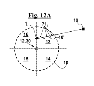
With reference to the sequence diagram of Figs. 12A-12C, a bullet 1 shot at
a shooter position 19 enters observation zone 10 of radar system 30 (Fig.
12A),
more precisely it enters the zone corresponding to sector 13, where it travels
along trace 18' and where it is detected and tracked. Afterwards, the bullet
leaves
sector 13 and reaches sector 16 (Fig. 12B), where it travels along trace 18"
and
where it is detected and tracked.
In an exemplary embodiment, when a bullet 1 is revealed, acquisition,
control and processing unit 35 of radar unit 36 (Fig. 4) is configured for
carrying
out step 160 of tracking bullet 1 and of reconstructing a trajectory 20 of
bullet 1
starting from detections made in previous consecutive TIC, for example in the
same angular sector 13 or 14 or 15 or 16.
By so-called backtracking algorithms, the direction of provenience of bullet 1
and shooter position 19 are determined.
In other words, the algorithms for reconstructing the trajectory use range
and azimuth measurements (Figs. 10 and 11) in a polar reference system,
transform the trajectory into a Cartesian reference and then carry out the
fitting of
trajectory 18',18". To this purpose, as described, the Doppler analysis can be
exploited, thus obtaining a mixed algorithm, which uses both the range and
angle
measurements and the Doppler measurements of the radial speed, which is
substantially a derivative of the range. The algorithm is based on well-known
optimum estimate and recursive digital filtering techniques.
Fig. 13 shows a block diagram of step 160 of tracking and computing bullet
trajectory 18',18" (Fig. 1), up to step 180 of localizing shooter position 19
(Figs.
12A-12C), according to an exemplary embodiment of the invention. Step 160 of
CA 02891505 2015-05-14
WO 2014/068548
PCT/1B2013/059921
19
tracking and computing the trajectory can be represented as the operation of a
state machine that receives plot data 71j at each state and returns the
already
closed trajectories 18',18". In other words, on the basis of plot 71j, a step
161,162,164 of reconstructing traces 18',18" is carried out, when a shot is
fired,
as well as a step 163 of reconstructing or computing a line 20 that can be
assimilated to the trajectory of bullet 1, starting from traces 18',18".
More in detail, tracking step 160 includes:
¨ a step 161 of associating a plurality of plot data of points 71j to a
same trace
or to a same hypothesis of trace, and a trace managing step 162. Trace
managing step 162 comprises in turn:
¨ a step of updating a list of hypothesis of trace. Moreover, trace
managing
step 162 comprises a plurality of decision steps based on the content of the
traces of the list. In particular, trace managing step 162 comprises a step of
¨ transforming the hypothesis of traces including an adequate number of
plots
into traces, and steps of:
closing and displaying traces 18',18" (Figs. 12A, 12B) as completed traces,
i.e. as traces of targets that have already left observation zone 10 (Figs. 2
and 3). Displayed traces 18',18" can be used in a
¨ step 163 of reconstructing of trajectory 20 of bullet 1 (Fig. 12C).
Moreover, trace managing step 162 comprises further decision steps, such as
steps of:
¨ cancelling hypothesis of trace that have not been confirmed by an
adequate
number of plots 71i from the list of the hypothesis of trace;
¨ confirming hypothesis of trace in the list of the hypothesis of trace,
updating
the latter according to plot data 71j associated to the hypothesis of trace
and
memorizing the status of the algorithm;
¨ creating new hypothesis of trace starting from plots that are not
associated
with any trace.
On this basis, a trace updating step 164 is provided, in which the
parameters of each trace/hypothesis of trace are changed in the light of the
plot
associated to it, or considering that no plot has been associated with the
trace/hypothesis of trace. This step is a requirement for a
¨ step 165 of defining and updating a status that comprises a plurality of
traces and/or of hypothesis of trace. Each trace/hypothesis of trace contains
CA 02891505 2015-05-14
WO 2014/068548
PCT/1B2013/059921
the following data:
¨ a list of plots 71i;
¨ a foreseen status of bullet 1;
¨ a score of the hypothesis.
5 Status 165 is the object of trace managing step 162.
Starting from each trace/hypothesis of trace, it is possible to extract, by a
¨ prediction step 166, a forecast of a future position of bullet 1, in
terms of
range, speed and angle. At most, a plot can be associated with a single
trace/hypothesis of trace, and vice-versa.
10 In a
subsequent data-fusion step 170 (Fig. 1), traces 18',18" corresponding
to sectors 13 and 16, respectively, are fused with each other, and trajectory
20 of
bullet 1 is reconstructed (Fig. 12C). This occurs, for instance, in trajectory
reconstruction step 163, as shown in Fig. 13.
The reconstruction of the line can be carried out also by a technique of
15
computing a motion law of bullet 1, on the basis of the data obtained from
step
154 of generating plot 71i.
Acquisition, control and processing unit 35 (Fig. 4) can also be configured
for carrying out step 180 of backtracking and of determining the direction of
provenience of bullet 1, and of localizing shooter position 19 (Fig. 12C).
20
Backtracking step 180 may comprise step 170 of fusing traces 18',18" that
relate
to different sectors of observation zone 10.
In another exemplary embodiment, transceiver 33 comprises radar unit 36
configured to generate an LFMCW continuous waveform. In other words, radar
unit 36 is configured to generate a linearly frequency-modulated waveform.
With reference to Fig. 14, a possible step 150 is described (Fig. 1) of
processing the return signals in the case of a radar signal 43 comprising an
LFMCW waveform (linearly frequency-modulated continuous wave). In an
exemplary embodiment, radar unit 36 is configured for carrying out a range-
Doppler filtering step that is suitable for calculating the range and the
radial speed
of an object at the same time. Radar unit 36 is configured for determining,
after
the detection, the azimuth angle of the object by a monopulse technique. In
other
words, processing step 150 differs from the corresponding step of processing
the
double-frequency radar signal of Fig. 8 in that it comprises an adapted range-
Doppler filtering step 152' specifically conceived for waveform LFMCW. Adapted
CA 02891505 2015-05-14
WO 2014/068548
PCT/1B2013/059921
21
range-Doppler filtering step 152' makes it possible to calculate the range,
i.e. the
distance between radar site 12 and bullet 1, before carrying out threshold
detection step 155.
On the other hand, threshold detection step 155, for example a threshold
detection step that uses the CFAR technique and monopulse measuring and
computation step 156 can be carried out as they are carried out in the case of
a
radar signal comprising a double-frequency CW waveform, according to the
description of Figs. 9 and 11. Threshold detection steps 155 and angle
monopulse measuring and computation step 156 complete step 154 of
generating plot data 71j.
Also trajectory tracking and computing step 160, and step 180 of
backtracking and localizing shooter position 19, may be carried out as they
are in
the case of a radar signal comprising a double-frequency CW waveform,
according to the description of Fig. 13.
With reference to Fig. 15, in an exemplary embodiment, the radar system or
systems 30 comprise/s a radar unit 36 (Fig. 4) that is configured for
generating a
periodic waveform 43 according to the range-gating technique. In other words,
a
radar signal 43 (Figs. 5,6) is emitted during an emission step, i.e. during an
operation step of emission means TX of antenna unit 31 (Fig. 4) during a
emission time interval 62'. Afterwards, radar unit 36 turns off emission means
TX
of antenna unit 31 (Fig. 4). The emission step is repeated with a frequency
i.e. at
a rate that has a cycle duration 61 longer than emission time interval 62'.
After turning off the emission means, radar unit 36 turns on reception means
RX of antenna unit 31. Reception means RX remains active during a reception
time interval 62", during which the reception step is carried out, and during
which
emission means TX are inactive.
This way, the signals coming from the nearest zones, i.e. from zones that
have the shortest range, are attenuated more than the signals coming from the
farthest zones, i.e. from zones that have the longest range.
In particular, if duration 62' of the emission step and duration 62" of the
reception step are equal to each other, as In the case of Fig. 15, the
attenuation
decreases linearly down to a minimum value at instant t1, i.e. once a time
interval
has elapsed equal to duration 62' of the emission step since when emission
means of antenna unit 31 was turned on. Afterwards, the attenuation increases
CA 02891505 2015-05-14
WO 2014/068548
PCT/1B2013/059921
22
linearly up to a maximum value once a time interval has elapsed equal to
62'+62".
As shown still in Fig. 15, the duration of cycle 61, and emission time
interval
62' are selected so that the attenuation, i.e. the local sensitivity decrease,
has a
minimum value at a maximum observation distance 64, selected for example as a
distance of about 100 m.
Besides separating the emission instant from the reception instant and
limiting the effects of the coupling between emission means TX and reception
means RX, range-gated signal 43 makes it possible to reduce any noise arising
close to the radar device. For instance, this noise can be an electrostatic
noise,
such as the noise due to rain drops falling to the ground, or to metal or
electrostatically charged objects coming occasionally into contact with each
other.
By the range-gating technique, the saturation and the subsequent sensitivity
loss
of the receiver due to local noise can be prevented.
In summary, at a short distance, the attenuation or sensitivity decrease of
the contribution of the approaching bullet can be tolerated, while the
contribution
of the local electrostatic noise is substantially eliminated.
In particular, reception duration 62", during which only reception means RX
of antenna unit 31 are active, is complementary of emission time interval 62'
with
respect to the overall duration of cycle 61, in other words, reception means
RX is
turned on immediately after emission means TX of antenna unit 31 are turned
off.
As an alternative, once emission time interval 62' has elapsed in each cycle,
i.e. once emission means TX have been turned off, and before turning on
reception means RX of antenna unit 31, a separation time interval, not shown,
can be awaited, during which both emission means TX and reception means RX
are inactive. A separation time interval of a few nanoseconds makes it
possible to
further reduce the local noise and to eliminate the unwanted coupling of
emission
means TX and reception means RX, further dumping sudden changes with
respect to the mode CW. As well known, by awaiting a separation time interval
before turning on the reception means, a blind zone is created about radar
site
12, from which no return signal is received. However, the extension of this
blind
zone, with a separation time interval as indicated above, is very small, with
respect to the safety distance at which the bullets are detected effectively
so that
an operator can protect himself and/or react. For instance, with a separation
time
CA 02891505 2015-05-14
WO 2014/068548
PCT/1B2013/059921
23
interval of 20 nanoseconds, the extension of the blind zone is about 3 metres,
which is a distance much shorter than the safety distance at which a bullet
should
be detected.
Signal processing step 150, up to extraction 154 of plot data 71i (Figs.
8,14),
bullet tracking and trajectory computing step 160 (Fig. 13), data fusion step
170
of traces in distinct sectors, and step 180 of backtracking, calculating the
direction
of provenience and localizing shooter position 19, can be carried out as
described
for devices in which radar unit 36 is configured for permanently emitting a
periodic CW or LFMCW signal (Figs. 8-14).
Still with reference to the block diagram of Fig. 1, step 180 of localizing
shooter position 19 is advantageously followed by a step 190 of generating an
alarm that can comprise displaying or notifying the direction of provenience
of
bullet 1 and displaying or notifying shooter position 19.
Fig. 16 shows an exemplary embodiment of the device according to the
invention, in which radar device 30 comprises an acoustic sensor 90. Acoustic
sensor 90 is configured for detecting an incoming compression wave 91
generated by a shot. In this case, backtracking step 180 of bullet 1 (Fig. 1)
is
stopped as soon as the acoustic sensor arranged immediately close to the radar
antenna, detects compression wave 91. This allows more accurately localizing
shooter position 19.
Fig. 17 shows a portable radar equipment 30, according to an exemplary
embodiment of the invention, for determining the trajectory of a bullet 1
fired by a
small firearm. Portable equipment 30 can be used to protect a movable position
such as a checkpoint, an outpost and the like, and is configured to be mounted
on a trestle 5. By equipment 30, operators 6 can estimate the direction of
provenience of bullet 1 and possibly even the coordinates of the shooter
position,
not shown. This makes it possible to take countermeasures.
In an exemplary embodiment, the portable equipment can be used for
protecting a vehicle 2, as shown in Fig. 18. In this case, the equipment
advantageously comprises an interface with an inertial system, not shown, in
order to restore the correct geographic reference or any position reference of
the
vehicle. This way, it is possible to determine the trajectory of bullets and
possibly
to localize the absolute shooter position, even if a sudden position change of
vehicle 2 or a high acceleration condition occurs, which is the case when
vehicle
CA 02891505 2015-05-14
WO 2014/068548
PCT/1B2013/059921
24
2 travels, in particular, on an irregular ground. In the exemplary embodiment
of
Fig. 18, the equipment comprises two radar devices 30',30", to be arranged at
a
front portion or at a rear portion of the vehicle, each radar device
comprising a
radar unit 36 and an antenna unit 31 as described above, in which the antenna
is
configured for inspecting two observation zones 10',10" before and behind the
vehicle.
The above description relates to one of the possible embodiments of the
present invention. Other embodiments can differ from what is described, even
if
they fall within the scope of invention, in some specific aspects such as the
waveform, the way the signal is processed, the decision logic means, the way
different detection system are integrated, in order to improve the localizaion
of the
shooter position and the like.
The description as above, of exemplary specific embodiments will so fully
reveal the invention according to the conceptual point of view, so that
others, by
applying current knowledge, will be able to modify and/or adapt for various
applications such embodiments without further research and without parting
from
the invention, and, accordingly, it is to be understood that such adaptations
and
modifications will have to be considered as equivalent to the specific
embodiments. The means and the materials to realise the different functions
described herein could have a different nature without, for this reason,
departing
from the scope of the invention. It is meant that the phraseology or
terminology
that is employed herein is for the purpose of description and not of
limitation.
Reference
1) Allen M.R. et al., in "A low-cost radar concept for bullet direction
finding", from
the acta of the 1996 IEEE national radar conference, held at the Michigan
University, Ann Arbor, Michigan May 13-16, 1996, IEEE New York, USA May
13, 1996, pages 20-207.