Note: Descriptions are shown in the official language in which they were submitted.
CA 02891580 2015-09-30
LED LIGHT APPARATUS
BACKGROUND OF THE INVENTION
1. Field of the Invention
[0002] This application relates generally to an illumination device and,
more specifically, to a LED illumination device that establishes a thermally-
conductive pathway between a LED light, a heat sink, and a light fixture
including the
LED illumination device.
2. Description of Related Art
[0003] Incandescent lights having a bi-pin connector such as those
commonly referred to as "G9" type lights, for example, are typically used in
light
fixtures installed at locations such as bathrooms. Such lights have a pair of
spaced-
apart pins electrically connected to a filament that, when energized, emits
light.
However, such lights are inefficient and convert a large portion of the
electric energy
received into heat, requiring the lights to be installed in a socket formed
from a
ceramic material or other suitable thermal insulator. The insulating material
thermally
insulates the light from its supporting fixture to prevent the fixture itself
from
becoming too hot.
[0004] Attempts to utilize more efficient light sources such as LED
lights
in G9-compatible sockets have focused on providing a G9-compatible pin
arrangement to a LED array. Lamps including such LED arrays typically include
many low-power LED bulbs electrically connected to a G9-compliant connector
that
can be installed in a conventional 09-compliant socket. Since such sockets
supply
1
CA 02891580 2015-05-01
WO 2014/074613 PCT/US2013/068772
AC electric power, however, each lamp is also provided with an onboard AC-to-
DC
converter circuit, which increases the cost of the lamps.
[0005] Although LED bulbs operate at a lower temperature than their
incandescent counterparts, the heat generated by the LEDs must be dissipated
to
prevent it from degrading the LED efficiency. In an effort to minimize the
heat
generated, conventional devices have traditionally utilized a large number of
low-
power LED chips spaced apart from each other. Including too few of the low-
power
LEDs in the array (or LEDs of insufficient power-rating) results in an
insufficient
amount of visible light being emitted to adequately replace an incandescent
bulb.
And including too many of the low-power LEDs in the array can result in a
power
consumption that at least partially offsets the power savings that make LEDs
an
attractive alternative to incandescent bulbs.
BRIEF SUMMARY OF THE INVENTION
[0006] According to one aspect, the subject application involves an
illumination device including a body formed of a thermally-conductive material
that
includes a planar heat transfer surface and a fastener that is compatible with
a base
that couples the body to the light fixture. A substrate formed, at least in
part from a
dielectric material, supports an array of light emitting diodes and a
plurality of
contacts electrically connected to the light emitting diodes. A thermally-
conductive
planar surface is provided to the dielectric material of the substrate to be
placed in
thermal communication with the heat transfer surface and conduct heat
generated by
the light emitting diodes to the body.
[0007] According to another aspect, the subject application involves a
light
fixture including a plurality of bases, and a plurality of wires that extend
through each
of the plurality of bases for conducting electric power. An illumination
device is
coupled to each of the plurality of bases, and includes a body formed of a
thermally-
conductive material. The body also includes a substantially-planar heat
transfer
surface and a fastener coupled to one of the bases. A substrate formed at
least in part
of a dielectric material supports an LED array including a plurality of light
emitting
diodes and a plurality of contacts electrically connected to the LED array and
the
wires extending through the base to which the body is coupled. A thermally-
2
CA 02891580 2015-05-01
WO 2014/074613 PCT/US2013/068772
conductive planar surface is provided to the dielectric material that is to be
placed in
thermal communication with the heat transfer surface to conduct heat generated
by the
LEDs to the body.
BRIEF DESCRIPTION OF SEVERAL VIEWS OF THE DRAWINGS
[0008] The invention may take physical form in certain parts and
arrangement of parts, embodiments of which will be described in detail in this
specification and illustrated in the accompanying drawings which form a part
hereof
and wherein:
[0009] FIG. 1 is a perspective view of a LED illumination device installed
on a light fixture;
[0010] FIG. 2 is a side view of a LED illumination device at least
partially
installed on a base that has been removed from a light fixture;
[0011] FIG. 3 is a top view of a LED illumination device without electrical
connections to an array of LEDs established or a fastener urging a substrate
supporting the array toward a body of the LED illumination device;
[0012] FIG. 4 is a top view of a LED illumination device with electrical
connections to an array of LEDs established and a plurality of fasteners
urging a
substrate supporting the array toward a body of the LED illumination device;
[0013] FIG. 5 is a bottom view into a bore formed in a body of the LED
illumination device, wherein the bore is to receive a portion of a base
provided to a
light fixture to install the LED illumination device onto the light fixture;
[0014] FIG. 6 is a plan view of a contact surface of a substrate supporting
an array of LEDs;
[0015] FIG. 7 is a top view of a heat-transfer surface of a body of a LED
illumination device;
[0016] FIG. 8 is a side, partially-exploded view of a LED illumination
device;
[0017] FIG. 9 is a perspective view of a plurality of LED illumination
devices installed on a light fixture coupled to a wall structure by mounting
hardware,
3
CA 02891580 2015-05-01
WO 2014/074613 PCT/US2013/068772
including a LED illumination device with a conically-shaped shield comprising
a
phosphor coating that at least partially encapsulates a plurality of royal-
blue LEDs to
produce an omni-directional distribution of light;
[0018] FIG. 10 is a perspective view of a LED illumination device installed
on a light fixture, the LED illumination device including a plurality of white
LEDs
that produce a substantially uni-directional distribution of light;
[0019] FIG. 11 is a perspective view of an embodiment of a body, where
wires extend within a channel formed along a portion of the body's external
periphery;
[0020] FIG. 12 is a perspective view of an embodiment of a body with a
portion of a generally-cylindrical external periphery cutaway;
[0021] FIG. 13 is a perspective view of a light fixture configured as an
outdoor lantern;
[0022] FIG. 14 is a view into a shade provided to an outdoor light fixture,
illustrating an embodiment of a LED illumination device supported by such a
light
fixture;
[0023] FIG. 15 is a perspective view of an alternate embodiment of a body
for installation as part of an outdoor light fixture; and
[0024] FIG. 16 is a partially exploded view of a substrate supporting a LED
on an alternate embodiment of a body and a PCB supporting a conditioning
circuit
that supplies electric power to the LED.
DETAILED DESCRIPTION OF THE INVENTION
[0025] Certain terminology is used herein for convenience only and is not
to be taken as a limitation on the present invention. Relative language used
herein is
best understood with reference to the drawings, in which like numerals are
used to
identify like or similar items. Further, in the drawings, certain features may
be shown
in somewhat schematic form.
[0026] It is also to be noted that the phrase "at least one of", if used
herein,
followed by a plurality of members herein means one of the members, or a
4
CA 02891580 2015-05-01
WO 2014/074613 PCT/US2013/068772
combination of more than one of the members. For example, the phrase "at least
one
of a first widget and a second widget" means in the present application: the
first
widget, the second widget, or the first widget and the second widget.
Likewise, "at
least one of a first widget, a second widget and a third widget" means in the
present
application: the first widget, the second widget, the third widget, the first
widget and
the second widget, the first widget and the third widget, the second widget
and the
third widget, or the first widget and the second widget and the third widget.
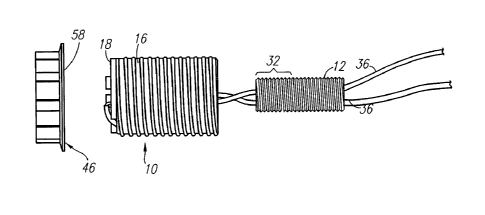
[0027] An illustrative embodiment of an LED illumination device 10 is
shown in FIG. 1 installed on a base 12 (FIGs. 2 and 8) of a light fixture 14.
The base
12 is described herein as a 1/8-27 NPSM nipple formed from copper, steel with
zinc
plating, brass or other thermally-conductive metal, for example, provided to a
G9
candelabra-type light fixture 14 that supports a plurality of the LED
illumination
devices 10 to clearly describe the present technology. Such a base 12 includes
an
annular, substantially cylindrical metal tube defining an interior passage
through
which wires 36 that are to conduct DC electric power used to illuminate the
fixture 14
extend. But it is to be understood that the present embodiment is described
for
illustrative purposes, and that the scope of the present disclosure is not so
limited.
[0028] As shown in FIG. 1, the LED illumination device 10 includes a
body 16 on which a substrate 18 supporting an array 20 of LEDs 22 rests. The
body
16 of the illustrative embodiment is generally cylindrical in shape, formed
from a
solid aluminum ingot or bar, for example. Alternate embodiments can utilize a
body
16 formed by die casting a metal alloy including zinc, aluminum, magnesium,
copper,
other thermally-conductive material, or any combination thereof For instance,
the
body 16 can be formed by die casting a material commonly referred to as zamak
(ZA3), but any other suitable thermal conductor is also includes within the
scope of
the present disclosure. The material forming the body 16 can optionally
include one
or more materials also forming the base 12 to minimize galvanic reduction. An
externally-threaded portion 24 extends along a substantial portion, and
optionally the
entire length of the body 16 along a longitudinal axis that is concentric with
a bore 26
described below and shown in FIG. 5. Alternate embodiments of the body 16 can
be
formed from other thermally-conductive materials such as metals (e.g., copper,
steel,
etc...), metal alloys, and any other material having a thermal conductivity of
at least
W/(m=K) at 25 C. Metallic embodiments of the body 16 are also electrically
5
CA 02891580 2015-05-01
WO 2014/074613 PCT/US2013/068772
conductive, thereby establishing an electrically-conductive pathway between
the body
16 and the base 12 when they are coupled together as described herein. Thus,
stray
current introduced to the body 16 can be conducted to the base 12, and
optionally
other portions of the fixture 14 through the base 12 when assembled, resulting
in
operation of a circuit interrupter or other such device to interrupt the
supply of such
stray current.
[0029] An embodiment of a bore 26, shown in FIG. 5, is defined by an
internally-threaded surface 28 of the body 16, and has a depth of
approximately half
the length of the body 16. In other words, the bore 26 according to the
present
embodiment extends about half way through the body 16 in a lengthwise
direction
along the longitudinal axis, but terminates short of a heat transfer surface
30 (FIG. 7)
at a terminal end of the body 16 against which the substrate 18 supporting the
array 20
of LEDs 22 is to rest. Thus, a portion of the material forming the body 16
remains
between the terminal end of the bore 26 and the heat transfer surface 30.
Although
described as extending approximately half the length of the body 16, alternate
embodiments of the bore 26 can have any desired depth that is less than the
entire
length of the body 16. Yet other embodiments of the bore 26 can extend
entirely
through the body 16, forming an annular ring of the material forming the body
16
similar to the annular portion of the body 16 described below with reference
to FIG.
5.
[0030] The diameter of the bore 26 is suitable for the threading provided
to
the internally-threaded surface 28 to cooperate with an externally-threaded
portion 32
(FIG. 8) of the base 12, thereby removably coupling (e.g., capable of repeated
installation and removal without incurring structural damage preventing
further use)
the body 16 to the base 12 as shown in FIG. 2. The wall thickness T (FIG. 5)
of the
annular portion 34 of the body material surrounding the bore 26 can be
selected to
provide the body 16 with sufficient thermal mass to dissipate at least a
portion of the
heat generated by the array 20 of LEDs 22 for the specific application of the
LED
illumination device 10. For instance, an embodiment of the body 16 can be
formed as
a solid metallic structure having a wall thickness T surrounding the bore 26
of at least
1/8 of an inch (1/8 in.), and optionally at least one quarter of an inch (1/4
in.).
[0031] With the body 16 screwed onto the base 12, cooperation between
the internally-threaded surface 28 of the body 16 and the externally-threaded
portion
6
CA 02891580 2015-05-01
WO 2014/074613 PCT/US2013/068772
32 of the base 12 provided to the light fixture 14 also establishes a
thermally-
conductive path along which heat can be conducted from the body 16 to the base
12.
The cooperation of these threaded portions involves contact between these
metallic
surfaces, thereby establishing a continuous, metallic thermally conductive
path along
which heat from the LEDs 22 can be conducted to the light fixture 14 or other
heat
sink. From the base 12, the heat can be conducted to another portion of the
light
fixture 14, thereby expanding the thermal pathways through which heat can be
conducted away from the body 16 and dissipated into the ambient environment of
the
light fixture 14.
[0032] As shown in FIG. 7, a plurality of apertures are formed adjacent to,
or in, the heat transfer surface 30, optionally extending entirely through the
heat
transfer surface 30. Electrically-conductive wires 36 (FIGs. 2, 8) extend
through the
one, or a plurality of the apertures 38 to supply electric power to the LEDs
22 on the
substrate 18. According to the present embodiment, the apertures 38 extend
entirely
through the material forming the body 16 that remains between the bore 26 and
the
heat transfer surface 30. With the LED illumination device 10 installed on the
base
12, the wires 36 can extend through the base 12 inserted into the bore 26, and
through
the apertures 38 to reach the heat transfer surface 30. Since conventional
lights are
merely provided with a G9-compatible connector to be retrofit into a
conventional G9
light fixture 14 supplying AC electric power, such conventional lights are
required to
include an on-board AC-to-DC converter. The LED illumination device 10
described
herein can optionally lack an on-board AC-to-DC converter dedicated to supply
DC
electric energy specifically to the LEDs 22 on the respective LED illumination
device
10. Instead, a common AC-to-DC converter can optionally be provided to the
light
fixture 14 at a location remote from the LED illumination devices 10 (e.g.,
separate
from the body 16), to convert AC electric power from an AC mains outlet, for
example, to DC electric power for each of a plurality of the LED illumination
devices
provided to the light fixture 14. In other words, a fixture AC-to-DC converter
39
(shown with hidden lines in FIG. 9) can be coupled to the fixture 14 at a
location
where it is concealed from view when the fixture 14 is observed in a typically
installation (e.g., mounted with mounting hardware such as a bracket to a wall
structure) in a residential dwelling to supply DC electric power to each of
the plurality
of illumination devices 10 provided to the fixture 14. When an illumination
device 10
7
CA 02891580 2015-05-01
WO 2014/074613 PCT/US2013/068772
is separated (i.e., removed) from the fixture 14, the fixture AC-to-DC
converter 39
remains in place on the fixture 14. Thus, AC electric power introduced to the
light
fixture 14 from an external source (e.g., AC mains wall outlet or wiring) can
be
converted into DC electric power by circuit components provided to the light
fixture
14 and delivered to each of the plurality of LED illumination devices 10
provided to
the light fixture 14.
[0033] According to alternate embodiments, the wires 36 can optionally
extend along a length of the body 16 externally of the bore 26. For example,
FIG. 11
shows another illustrative embodiment of the body 16 including a generally C-
shaped
channel 64 formed to extend along a portion of the external periphery of the
body 16,
extending lengthwise toward the heat transfer surface 30, to receive the wires
36
supplying DC electric power that extend through the base 12 to the heat
transfer
surface 30. Such channels can be formed in the body 16 in a manner that
involves
cutting away a portion of the threading provided to the externally-threaded
portion 24
of the body 16, but does not interfere with the threaded engagement between
the body
16 and a collar 46 (FIG. 2) with an internally-threaded surface, for example,
or other
device. An interior passage 66 extends between the bore 26 and the channel 64
to
allow the wires 36 to exit the bore 26 and enter the channel 64 en route to
the contacts
42 through which electric power is introduced to energize the LEDs 22 as
described
below.
[0034] Another illustrative embodiment of the body 16 appears in FIG. 12.
As shown, the body 16 is adapted to be compatible with type-A lamps with an
E26 or
E27 fitting, for example. As shown, the body 16 includes the threaded portion
24 of
the external periphery, with a truncated region 68 extending lengthwise along
the
body 16. In other words, such an embodiment of the body 16 can be envisioned
as
including a cylindrical, threaded external surface with a portion of the
circumference
cut away by a planar surface, optionally on one or opposite sides of the body
16. The
remaining portions of the threaded surface remain compatible with the
internally-
threaded surface 28 of the body 16 defining the bore 26.
[0035] At least one, and optionally a plurality of fastener apertures 40
are
also formed adjacent to, or through the heat transfer surface 30 to receive
fasteners
that, when installed, urge the substrate 18 against the heat transfer surface
30. The
8
CA 02891580 2015-05-01
WO 2014/074613 PCT/US2013/068772
fastener apertures 40 can extend entirely, or optionally partially through the
body
material remaining between the bore 26 and the heat transfer surface 30.
[0036] A top view of an embodiment of the substrate 18 resting on the heat
transfer surface 30, without being electrically connected to the wires 36 is
shown in
FIG. 3. The substrate 18 supports a plurality of LEDs 22 arranged in an array
20.
Contacts 42 electrically connected to supply electric power to the LEDs 22 are
exposed at an outwardly-facing surface of the substrate 18, a portion (e.g., a
layer) of
which can be formed from a dielectric material. Thus, electric power
introduced to
the contacts 42 is conducted by traces, vias, and other conductors known in
printed
circuit board technology concealed from view by the outwardly facing surface
of the
substrate 18 to illuminate the LEDs 22. Other circuit components used to
supply the
electric power to the LEDs 22 can also be supported by the substrate 18.
Cutout
regions 44 defined by the substrate 18 reveal the apertures 38, 40 that would
otherwise be concealed by the substrate 18. According to alternate
embodiments, a
portion of the overall circuit supply the electric power to the LEDs 22 can be
supported by, or optionally within an aperture or cavity defined by the body
16. For
example, a current regulator for establishing a desire electric current
suitable to power
the particular LEDs 22 can be provided to the body 16. Yet other embodiments
can
distribute the circuit components between on-board components such as the
current
regulator provided to the body 16 and remote components provided elsewhere on
the
fixture 14, such as behind, and concealed from view by a back plate. An
example of
such a remote component includes, but is not limited to a voltage regulator
such as a
voltage modulator that establishes a desired voltage of the electric power
supplied to
the circuit components provided to the body 16, and optionally to the circuit
components provided to a plurality of different bodies supported by the
fixture 14.
The electric power with this desired voltage can be received by an on-board
current
regulator to establish the desired current at the body 16, and optionally at
each of the
plurality of bodies 16 provided to the fixture 14.
[0037] An embodiment of an underside 48 of the substrate 18 is shown in
FIG. 6. The underside 48 can be coated, laminated to, or otherwise provided
with a
thermally-conductive material such as a metal or metal alloy. The substrate 18
can be
a laminate comprising at least the thermally conductive material exposed at
the
underside 48 as shown in FIG. 6, a layer of a dielectric material in which the
traces,
9
CA 02891580 2015-05-01
WO 2014/074613 PCT/US2013/068772
vias and other electrically-conductive pathways are formed and insulated from
each
other, and the outwardly-facing surface of the substrate 18 provided with the
contacts
42 shown in FIG. 3. However, any suitable number of layers to establish the
desired
electrical connections yet prevent undesired shorts from occurring between
each of
the contacts 42 and between the contacts 42 and the body 16 is within the
scope of the
present disclosure. The thermally-conductive material exposed along the
underside
48 of the substrate can optionally be electrically insulated from the LEDs 22
by the
dielectric material of the substrate 18. However, the dielectric material
region of the
substrate 18 separating the LEDs 22 from the thermally-conductive material
provided
to the underside 48 includes dimensions suitable to permit heat generated by
the
LEDs22 to be conducted away from the LEDs 22 through that thermally-conductive
material toward the heat transfer surface 30 of the body 16.
[0038] The thermally-conductive material exposed at the underside 48
(e.g., a material having a thermal conductivity of at least 10 W/(m=K) at 25
C) is to be
placed in close proximity to, and optionally in contact with, the heat
transfer surface
30 of the body 16. A thermally-conductive adhesive, such as a silver-
containing paste
for example, can be applied to promote adhesion between the underside 48 and
the
heat transfer surface 30, to promote intimate thermal contact between the
underside
48 and the heat transfer surface 30, or a combination thereof. According to
alternate
embodiments, other thermal interface media such as thermally conductive
adhesive
transfer tape 8805 from 3MTm, for example, can be provided to the underside 48
of
the substrate 18 to promote a thermally-conductive interface between the
substrate 18
and the heat transfer surface 30. The generally-planar heat transfer surface
30 and the
similarly-planar underside 48 establish a large surface area through which
heat
emitted from the LEDs 22 can be conducted from the substrate 18 to the body
16.
[0039] As shown in FIG. 4, fasteners 50 formed from a dielectric material
such as Nylon (e.g., polyamide materials), for example, can optionally be
inserted
through the cutout regions 44 defined by the substrate 18 and into the
fastener
apertures 40 to urge the underside 48 of the substrate 18 toward the heat
transfer
surface 30. The use of materials such as Nylon or other polymeric materials,
for
example, to form the fasteners 50 allows the fasteners 50 to be substantially
elastically
deformed when installed to urge the substrate 18 toward the body 16. Fasteners
50
can optionally include a threaded portion that cooperates with compatible
threading
CA 02891580 2015-05-01
WO 2014/074613 PCT/US2013/068772
provided to the apertures 40 formed in the body 16. When screwed into the
apertures
40, a flanged portion forming a head of the fastener 50 can make contact with
the
outwardly exposed surface of the substrate 18. Continued insertion of the
fasteners 50
can cause the threaded portion thereof to be further inserted into the
apertures 40,
thereby elongating the fastener 50 as the head remains in contact with the
exposed
surface of the substrate 18. This elongation can exert a suitable urging force
on the
substrate 18 without damaging the substrate 18 or body 16, and can accommodate
thermal expansion and/or contraction that may occur as a result of the heat
generated
by the illumination device 10. Such fasteners 50, formed from a dielectric
material,
also guard against electrical shorts between the substrate 18 and the body 18.
With
the substrate 18 in place, the wires 36 extending through the apertures 38 can
be
soldered or otherwise coupled in an electrically-conductive manner to the
contacts 42.
[0040] The LEDs 22 can be selected to emit any desired wavelength of
light to emit a desired light color (e.g., color temperature). The LEDs 22 can
optionally be selected to include a lens or cover provided with a phosphor
coating to
alter the wavelength of light emitted to achieve a desired light color.
However,
alternate embodiments of the LEDs 22 can lack such a coating, natively
emitting a
blue or other-colored light instead depending on the semi-conducting materials
used
in forming the LED. A decorative shade 52 having a phosphor coating such as
that
shown in FIG. 9, for example, can be coupled to the body 16 or other portion
of the
LED illumination device 10 to absorb the native light emitted by the LEDs 22
at its
native wavelength, or otherwise alter the wavelength or other property of the
light, to
emit light of the desired wavelength.
[0041] Another decorative shade 54 can optionally be placed over the body
16 to also conceal the body 16, or a portion thereof, from view, as shown in
FIG. 9.
With the shade 54 in place, the collar 42 (FIGs. 2 and 8) can be inserted
through an
aperture 56 leading to an interior of the shade 54, and placed over a base of
the shade
54. The diameter of a flange 58 (FIGs. 2 and 8) protruding outwardly from the
collar
42 is greater than a dimension of an aperture through which the body 16
extends
while the shade 54 is in place, thereby interfering with removal of the shade
54.
[0042] FIG. 10 illustrates another embodiment of a shade 60 that can be
provided to the LED illumination device 10. As shown in FIG. 10, the shade 60
is
formed from a substantially-transparent glass, and includes an internally-
threaded
11
CA 02891580 2015-05-01
WO 2014/074613 PCT/US2013/068772
base region 62. The threading provided to the internally-threaded base region
62
engages the threading provided to the externally-threaded portion 24 of the
body 16,
thereby securing the shade 60 in place to encapsulate the LEDs 22.
[0043] To install the illumination device 10 on the fixture 14, a
conventional G9 or other type of bulb and socket, along with an existing base,
can be
removed from the fixture 14. The existing base can be reused if it includes
the
externally-threaded portion 32, or a replacement base 12 compatible with the
fixture
14 and including the externally-threaded portion 32 can be provided. The
proximate
end of the bore 26 is positioned concentrically over the end of the base 12
and rotated
such that the internal threads within the bore 26 cooperate with the
externally-
threaded portion 32 of the base 12. Wires 36 (e.g., one positive and the other
a
reference potential) of the fixture 14 for conducting DC electric energy to be
delivered to the LEDs 22 that extend through the interior passage of the base
12 are
fed through an opposite end of the base 12 and into the bore 26 defined by the
body
16. Terminal ends of the wires 36 are fed through the apertures 38 in the heat
transfer
surface 30 to be electrically connected to the contacts 42 provided to the
substrate
where the DC electric energy is to be supplied to the LEDs 22. The present
embodiment allows for relative rotation between the body 16 and the base 12
without
twisting the wires 36 as a result.
[0044] According to alternate embodiments, the wires can be inserted
through the base 12 prior to the body 16 being screwed onto the externally-
threaded
portion 32 of the base 12. Thereafter, the body 16 is lowered to be concentric
with
the externally-threaded portion 32 of the base 12 and rotated relative to the
base 12 so
as to be screwed onto the base 12. The length of the wires 36 allows them to
be
twisted as a result of rotation of the body 16 without being damaged.
[0045] According to yet other embodiments, the wires 36 can be segments
that are to be added as extensions to the existing wires provided to the
fixture 14. For
example, the wires 36 can be separate from the fixture 14, and the terminal
ends of the
wires 36 inserted into the apertures 38 and fed downwardly through the bore 26
and
then internal passage of the base 12 from the heat transfer surface 30. One
end of the
wires 36 can remain extending outwardly from the heat transfer surface 30 to
be
electrically connected by soldering or otherwise to the contacts 42 of the
substrate 18.
The opposite ends of the wires 36 that were fed through the bore 26 and base
12, can
12
CA 02891580 2015-05-01
WO 2014/074613 PCT/US2013/068772
be soldered or otherwise electrically connected to wiring provided to the
fixture 14.
For example, the wiring provided to the fixture 14 can be existing wiring, or
can be
wiring that extends from an aftermarket AC-to-DC converter added to the
fixture 14
for supplying DC electric power to the plurality of illuminating devices 10
provided
to the fixture 14.
[0046] Regardless of the order and manner in which the body 16 is coupled
to the base 12 and the wires 36 installed, the substrate 18 supporting the
LEDs 22 can
be installed on the heat transfer surface 30. A metallic or otherwise
thermally-
conductive coating provided to the underside 48 of the substrate can be placed
in
direct contact with the heat transfer surface 30, or enhanced thermal contact
can be
established through an intermediary material such as thermally-conductive
paste or
tape. Once in place the fasteners 50 can be installed to provide additional
support to
the substrate and urge the substrate 18 toward the heat transfer surface 30.
The
terminal ends of the wires 36 can also be soldered, or otherwise electrically
connected
to the terminals 42.
[0047] If desired, a lens, shade or other cover can be placed over the
substrate 18 on the body 16 installed on the fixture 14. An optional collar 46
with an
internally-threaded passage can be threaded onto the externally-exposed
threads of the
body 16 to secure the cover in place on the fixture 14.
[0048] FIGs. 13 and 14 show another illustrative embodiment of a light
fixture 140 including an embodiment of the LED illumination device 110, which
is
hidden in the view of FIG. 13 and shown in broken lines. The light fixture 140
can be
an outdoor light fixture having a shade 141 and mounting plate 145 each formed
from
a metal or metal alloy, configured to resemble a hanging lantern as shown in
FIG. 13.
An arm 147 extends between the shade 141 and the mounting plate 145 to form an
internal conduit through which electrical wiring can extend to conduct
electric power,
and can also optionally be formed from a metal or metal alloy.
[0049] A base 112 optionally formed from an externally-threaded metal
tube extends downwardly from the arm 147 and cooperates with an internally-
threaded interior passage defined by a body 116 in a manner similar to that
described
above for the connection between the base 12 and body 16. The base 112 can
also
adhere to the 1/8-27 NPSM requirements, or comply with a different size
standard for
13
CA 02891580 2015-05-01
WO 2014/074613 PCT/US2013/068772
light fixtures 14. A metal washer 151 can optionally be disposed between a
flange
155 that projects radially outward from the external periphery of the base 112
and a
flange 157 that projects radially outward from a proximate end of the body
116. The
metal washer 151 adds to the thermal mass for dissipating heat generated by an
LED
122 (FIG. 14) supported on a substrate 118 in thermal communication with a
heat
transfer surface 130 adjacent to a distal end of the body 116. Contact between
the
metal washer 151 and the flange 157 establishes a suitable surface area
through which
heat is to be conducted away from the body 116. The metal washer 151 can
optionally be placed in contact with portions of the shade 141 to establish a
thermally-
conductive pathway between the body 116 and the shade 141 through which heat
can
conducted away from the body 116 to the shade 141, and optionally any other
thermally-conductive materials in thermal communication with the shade 141,
such as
the arm 147 and the mounting plate 145, for example. Embodiments of the metal
washer 151 can be configured with dimensions specific to the light fixture 140
on
which it is to be installed.
[0050] As shown in FIG. 14, looking into the shade 141, a substrate 118
supporting a single LED 122 is coupled against the heat transfer surface 130
of the
body 116. Although only a single LED 122 is shown in the embodiment of FIG.
14, a
plurality of LEDs 122 could be utilized without departing from the scope of
the
present disclosure. As described above, a thermally conductive paste, thermal
tape, or
other substance promoting intimate thermal contact between a metallic
underside of
the substrate 118 and the heat transfer surface 130 can be disposed there
between the
substrate 118 and the heat transfer surface 130.
[0051] Unlike the embodiments discussed above, the heat transfer surface
130 is recessed, surrounded by an annular ring 161. Further, a printed circuit
board
("PCB") 167, shown in FIG. 16, supporting electronic components 169 forming a
driver circuit for conditioning the electric power to be supplied to energize
the LED
122 can optionally be disposed within an interior of the body 116. For
example, the
PCB 167 can optionally be coupled against a portion of the material forming
the heat
transfer surface 130, opposite the substrate 118. The driver circuit can
rectify AC
electric power to supply DC electric power to the LED 122, can step up/step
down the
voltage of the electric power supplied, or a combination thereof. In other
words, the
substrate 118 can be supported adjacent to the heat transfer surface 130, and
the PCB
14
CA 02891580 2015-05-01
WO 2014/074613 PCT/US2013/068772
167 can be supported adjacent to an opposite side of the material forming the
heat
transfer surface 130. A plurality of apertures 165 (FIG. 15) are formed in the
heat
transfer surface 130 to receive fasteners to hold the substrate 118 in place
and/or
allow electrical wires to extend through the heat transfer surface 130.
[0052] Illustrative embodiments have been described, hereinabove. It will
be apparent to those skilled in the art that the above devices and methods may
incorporate changes and modifications without departing from the general scope
of
this invention. It is intended to include all such modifications and
alterations within
the scope of the present invention. Furthermore, to the extent that the term
"includes"
is used in either the detailed description or the claims, such term is
intended to be
inclusive in a manner similar to the term "comprising" as "comprising" is
interpreted
when employed as a transitional word in a claim.